

P8X32A-Q44 ProtoBoard - Your Input Requested from Parallax
 Ken Gracey
Posts: 7,420
Ken Gracey
Posts: 7,420
Hello Prop Users:
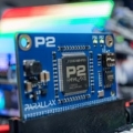
Parallax is beginning design of a through-hole project board for the Propeller, very similar to those we have designed for the SX chip. Here's a example: http://www.parallax.com/detail.asp?product_id=45300.
The P8X32A-Q44 Proto Board would have a·target price·of less than $15.00. The purpose of this·product is to provide a permanent project board for our customers. These boards are often dedicated to specific projects by our customers, somewhere in between 1 and 10 units. The design is intended to have the minimal complement of components required to run a Propeller, plus some handy design features to enable·productive point to point soldering.
The design is currently defined as follows:
The more hardware we throw into the design, the more it costs (everybody). There's a balance between providing·a minimal amount of·design features and·components to get somebody started versus throwing in so many features that the design looks like it's only·overly targeted towards specific applications. Many of the user conveniences are oriented around·[noparse][[/noparse]low-cost] PCB design·features instead of·adding·the·kitchen sink.
For us to produce·the P8X32A-Q44·Proto Board and offer it at this price we need to sell many of them. There's no profit in this product, but it needs to pay for itself.·This needs to be a board you'll consume, which is why I seek your input on this thread.·This is your·opportunity to weigh in on feature requests to tell us what you'd like to see in the design.
Thanks ahead of time for your thoughts.
Sincerely,
Ken Gracey
Parallax, Inc.
P.S. From the moment we start the design (this week or next week) it will take 4-5 months to have this product on our shelves. Believe me, this time passes slowly on our end too!
Parallax is beginning design of a through-hole project board for the Propeller, very similar to those we have designed for the SX chip. Here's a example: http://www.parallax.com/detail.asp?product_id=45300.
The P8X32A-Q44 Proto Board would have a·target price·of less than $15.00. The purpose of this·product is to provide a permanent project board for our customers. These boards are often dedicated to specific projects by our customers, somewhere in between 1 and 10 units. The design is intended to have the minimal complement of components required to run a Propeller, plus some handy design features to enable·productive point to point soldering.
The design is currently defined as follows:
- Surface-mounted P8X32A-Q44 Processor, EEPROM and clock
- Power light with three-position switch (0 = off, 1 = power to all supplies except a few servo ports, 2 = power to all places)
- 3” x 4” size, with mounting holes the same as the BOE, Super Carrier, and SX Proto Boards (this enables use on our Boe-Bots, or within any future enclosures or other mounting-hole specific products we may release)
- Dual power supply: 5V, 3.3V, and Vss
- Two (2) 47 uF capacitors across the 5V power supply for servo management
- Friendly power rails along the edge of the board for multiple connection points
- Several·rows of connected·0.1" pads for easy point-to-point soldering, providing 1x2 or 1x3 connections
- (2) 3-pin locations for servo connections, or other 3-pin devices made by Parallax (serial LCDs, Ping))), PIR, etc)
- Ample through-hole area for your projects
- Strain-relief holes for wires leading off the board
- PropPlug and PropClip programming connections
- Possible inclusion of a PS/2, VGA port pin-out pads for customer populating with commonly available connectors
- A/D ports near the Propeller
- No breadboard.
The more hardware we throw into the design, the more it costs (everybody). There's a balance between providing·a minimal amount of·design features and·components to get somebody started versus throwing in so many features that the design looks like it's only·overly targeted towards specific applications. Many of the user conveniences are oriented around·[noparse][[/noparse]low-cost] PCB design·features instead of·adding·the·kitchen sink.
For us to produce·the P8X32A-Q44·Proto Board and offer it at this price we need to sell many of them. There's no profit in this product, but it needs to pay for itself.·This needs to be a board you'll consume, which is why I seek your input on this thread.·This is your·opportunity to weigh in on feature requests to tell us what you'd like to see in the design.
Thanks ahead of time for your thoughts.
Sincerely,
Ken Gracey
Parallax, Inc.
P.S. From the moment we start the design (this week or next week) it will take 4-5 months to have this product on our shelves. Believe me, this time passes slowly on our end too!
Comments
Less than $15?? Are you sure you typed that correctly? [noparse]:)[/noparse] That's less than a Propeller itself!
Maybe it's just me, but I'm always confused by solder boards that have single holes with no connections to adjacent holes. How do you connect 2 components? So, I'm glad to see this:
Several rows of connected 0.1" pads for easy point-to-point soldering, providing 1x2 or 1x3 connections
-Martin
▔▔▔▔▔▔▔▔▔▔▔▔▔▔▔▔▔▔▔▔▔▔▔▔
Martin Hebel
Personal Links with plenty of BASIC Stamp info
StampPlot - Graphical Data Acquisition and Control
AppBee - XBee ZigBee / IEEE 802.15.4 Adapters & Devices
2) If the cost differential is small enough, please seriously consider using a 64K x 8 EEPROM instead of a 32K x 8.
Propellers are coming down in price, shortly. The P8X32A-Q44 Proto Board is product for marketing the Prop (for us) and a problem solver (for you). As long as the Propeller line is taking flight with some volume users to pay the way, we're able to invest back into hobbyists and educators!
And your second question.
When I'm using one of our boards without the 1x2 or 1x3 connected holes, I tend to put a component into the hole, fold over the lead underneath the board, and use it as some kind of structural solder connection point for another wire or component. I also find myself snaking leads from the top, through the board, then up another hole. I admit to being a bit of a ding-dong when it comes to electronic assembly on through-hold boards. I had to call Chip on sunday evening to ask him the question you posed above about single holes, just to see what he'd say. He didn't have any real answers except "look, Ken, you get to wire-wrap or solder". Then he directed me to go look at some cool amplifiers and speaker enclosure designs on the web - totally unrelated.
Mike,
Should be okay on both requests. Will confirm once we're underway.
Thanks,
Ken Gracey
Parallax, Inc.
Sid
▔▔▔▔▔▔▔▔▔▔▔▔▔▔▔▔▔▔▔▔▔▔▔▔
Sid Weaver
Need a TV Module?
Newzed@aol.com
·
www.parallax.com/detail.asp?product_id=32300
Don't get me wrong, I would love $15 for a prop kit.
Also, what about reducing the price of the PropStick?
▔▔▔▔▔▔▔▔▔▔▔▔▔▔▔▔▔▔▔▔▔▔▔▔
Coders' Hangout
A place for programmers to hangout!
http://www.codershangout.com
METROID?
Metroid Classic
Love the idea -- time's already going too slowly
Please ensure that we have access to ALL the pins...
Any chance you'd consider doing it similar to the Mecanique 'Flash-Lab' (e.g. stackable) system [noparse]/noparse]see [url=http://www.mecanique.co.uk/products/flash-lab/flash-board-main.html]http://www.mecanique.co.uk/products/flash-lab/flash-board-main.html[/url?
▔▔▔▔▔▔▔▔▔▔▔▔▔▔▔▔▔▔▔▔▔▔▔▔
Cheers,
Simon
Sounds great [noparse]:)[/noparse]
Here's my wishlist:
- thru hole pads for an RS-232 port, with a surface mount maxim chip (heck put a DB9 connector on it!)
- a second i2c socket for another memory part like a ferroram chip, and as someone else already suggested, using a bigger eeprom for the boot eeprom to store additional code / data
- love the a/d idea, maybe use an i2c part sharing the i2c pins with the eeprom? 8 channels would be grand...
- I like the idea of a VGA connector, even if it and the resistors needed are not populated
- ALL the propeller pins to go to the prototyping area
- I like the 1x3 pads idea, far less messy than 'gobbing' leads togeather
- if you put the PS/2 connector on, could you stack two of them for keyboard/mouse?
- better documentation or tech notes on the counter/timers and video circuitry in the chip; I've been reading the spin files, and its not bad, but it really should be in the manual, or in a separate "advanced" manual
- a simulator/debugger; I believe I read in another thread that someone started writing a cycle accurate emulator - it would be GREAT to be able to debug code properly
Best Regards,
Bill
p.s.
I just ordered the starter package and four chips; I can already think of a dozen uses for them...
·
The other thing that I see is the EEPROM problem, everybody wants more, so how about having an EEPROM socket, and at the time of purchase I can decide what size EEPROM I want to plug in.
Ray
2. Reduce the 4-5 month lead time to 1-2 months. I spend more time soldering during the winter months [noparse];)[/noparse]
3. In the interim, how about reducing the price on the Prop Stick.
Yes to your list; And YES to include the PS/2 Mouse and Keyboard, and VGA port pinouts. Maybe don't need two EEPROM extra zones, like on SX28, but maybe only one if a 64KB EEPROM is included.
More suggestions:
1. (* Ample through-hole area for your projects)
Provide a zone, say on the very right, for a 2 x 20 pin header 'zone'. I purchased a SX28 protoboard, looked like a 2 x 20 would fit from the picture. Maybe if one cut some of the Vin, Vdd and Vss pads loose one could.
2. (* Ample through-hole area for your projects)
And provide enough pads vertically so a 40 pin, 0.6" wide IC could be mounted without severe cutting signals loose.
3. Maybe even a DB9 zone for serial interfacing capability. Just the pads and silk screen.
▔▔▔▔▔▔▔▔▔▔▔▔▔▔▔▔▔▔▔▔▔▔▔▔
Harley Shanko
h.a.s. designn
> (2) 3-pin locations for servo connections, or other 3-pin devices made by Parallax (serial LCDs, Ping))), PIR, etc) I would up the count to at least 5 (2 servos for wheels, 2 Ping)))s and a serial LCD make a minimal robot)
Please include pullups on both SCL and SDA of the EEPROM and provide access to those pins for extending that default I2C bus.
I'm glad to see this: Several rows of connected 0.1" pads for easy point-to-point soldering, providing 1x2 or 1x3 connections
Not interested in VGA.
An easy place to put a DIP 8 (adc chip)
I am looking forward to this.· This board followed by What's a Microntroller Propeller Edition could expand the market for the Propeller.
▔▔▔▔▔▔▔▔▔▔▔▔▔▔▔▔▔▔▔▔▔▔▔▔
Paul Baker
Propeller Applications Engineer
Parallax, Inc.
I'm not complaing but it makes me wonder how you priced the Prop Stick.
With that said... I'd like a 40 Pin Male connector with the Ability to stack on Daughterboards. Daughter Boards could then be really inexpensive. Mess up soldering and you can just remove and stack on a new board.
Thanks for your time.
Eric
Personally, to keep costs down and flexibility up, I would NOT like to see anyting populated on the board beyond power, crystal and boot flash.
That said, a smattering of pads (non surface mount??) laid out according to the popular requests would be all that should be supplied. This way anyone can fill-in the blanks according to some preset schematics and layouts.
Paul; Regarding the virtual ADC's, four would be nice as one can of course also use that configuration for DAC outputs.
What I would request is an orderly sequential grouping of all port bits on 0.1 centers, 8 per row, and extended with a Vss and Vdd on either end, so 10 pins per group. This will lead to easy expansion via connecters.
Cheers,
Peter (pjv)
I too would prefer 4 ADCs, but 2 would do. Particularly with the ability to use the same circuit for a DAC, 1 is not enough.
Are you planning to use TO-220 regulators or smaller?
▔▔▔▔▔▔▔▔▔▔▔▔▔▔▔▔▔▔▔▔▔▔▔▔
Who says you have to have knowledge to use it?
I've killed a fly with my bare mind.
Some of you have had questions and comments regarding PropSTICK pricing. And in view of Ken's announcement today, these are fair to bring up. One of the reasons for the current price, frankly, is that there's a middleman in the picture: me. I put the kits together, and Parallax buys them from me for resale. It was decided early on that providing a full kit of parts would provide a better value than just selling the bare boards, which was my original plan. So, in addition to the original development and prototyping costs, I have the boards fabbed, buy the components (except for the Propellers, jumper wires, and foam blocks, which Parallax consigns), have the documentation printed, kit everything up, check-weigh everything twice during the kitting process, and package, label, and ship them to Parallax. For this I make a reasonable profit. And, of course, Parallax gets a markup as well.
Sales of the PropSTICK have surpassed anything I might have imagined when I first designed it, and I really do appreciate its enthusiastic acceptance. If you would like to see more of the history and process behind getting the PropSTICK to market, you can check my forum thread here: http://forums.parallax.com/showthread.php?p=581759.
Many thanks to all!
Phil
Dual power,·prop clip pads, VGA pads, composit pads, ps2 pads, reset and power switches, eprom, clock and propeller. Plenty of·holes would be nice. Access to the vga, composit and ps2 pads via a buss wire jumper for either pin or connector access would be great.
If you would carry the connectors in the component shop, that would be nice also as this would help keep the cost down and we could purchase only what we need.
My suggestion would be to include the processor, EEPROM with pullup resistors, and clock (will this be a 5 mHz crystal?) and a barrel-style power connector, 5 and 3.3 regulators, 2-pos pwr switch and power indicator light.
Won't everyone need programming port parts? How much variation is there in the different ways that people interface to program the propeller? I use RS232 circuitry with a DB-9 connector; is that less commmon than some other means? Why not take a poll, see whether one method is used overwhelmingly, and then add its parts?
I'd suggest using the minimal sized EEPROM and use a 2-position switch. Add pads so whoever wants can add an additional EEPROM or a servo switch or additional capacitors on their own.
Pads for at least one DAC and ADC component area would be nice.
Please bring out ALL propeller lines for user projects!
Any chance the board could be marked not with the confusing "vdd, vss", but instead, a user-friendly "3.3v, gnd"? Why is "vdd, vss" better? If the board also provides a +5v line for accessories, well-marked voltage pads are even more important.
David
$15 , wow. the things i could build
dan
If Parallax is able to produce a header board like the one below, would be very attractive to those looking to minaturize the over all footprint of their projects.
your thoughts?
Nagi
▔▔▔▔▔▔▔▔▔▔▔▔▔▔▔▔▔▔▔▔▔▔▔▔
ALIBE - Artificial LIfe BEing. In search of building autonoumous land robot
http://fstop.crosscity.com/
http://icar.crosscity.com/
·
I do like the compact format; but appears to have to plug into 4 separate headers on another pcb.
Sort of seems to defeat Ken Gracey's approach of a base to i/f to other components required of the user's design. Probably impossible to please everyone with any one configuration. "LIFE!!!", as a friend used to comment.
▔▔▔▔▔▔▔▔▔▔▔▔▔▔▔▔▔▔▔▔▔▔▔▔
Harley Shanko
h.a.s. designn
I suppose a RESET switch would also be part of the board; or pads for one?
▔▔▔▔▔▔▔▔▔▔▔▔▔▔▔▔▔▔▔▔▔▔▔▔
Harley Shanko
h.a.s. designn
▔▔▔▔▔▔▔▔▔▔▔▔▔▔▔▔▔▔▔▔▔▔▔▔
Paul Baker
Propeller Applications Engineer
Parallax, Inc.
▔▔▔▔▔▔▔▔▔▔▔▔▔▔▔▔▔▔▔▔▔▔▔▔
Mike
I see your offer as a way for someone like me, who might produce 10 prototypes, to take advantage of the small package P8X32A-Q44 Prop chip.· I would suggest doing the bare minimum, with the exception of Mikes idea about adding the extra 32k and use a 64k eeprom.· You would be adding functionality (that most would find useful, I think) without adding extra components and minimal cost.· If you could do more of that (clever design) it would be nice.· I foresee buying them based solely on footprint of minimum parts, so if you could squeeze all the minimum parts as close as possible, and provide one, or multiple common interfaces (again clever design) such that one could go at it with the hacksaw, and still have built-in fucntional mounting holes for hte smaller (hacked) footprint.
Design contest, (free help):·
Make a request of the community to design the board for you.· This seems to be a growing trend in industry, and you are in a position where you would get more feedback than usual, due to this community.· Offer the winner $100 and free stuff, or something along those lines.· Also have the community vote on the final design, then your living in a democracy through-and-through!!!
Perhaps two kits:
Maybe, since boards are pretty cheap, offer us both a bare bones board, and one that might have all pins exposed, but interfaces/hardware for the more common items
Interface commonanlity:
Like I said before, clever design.· I'm not too familiar with the parts in the IC/hobby industry just yet, but I imagine that there are common sizes for enclosures, board interfaces, computer IDE interfaces, etc.. that might be satisfied.· Multiple mount holes (maybe·6 holes instead of 4, for instance) might be easy to include.
RS232, don't add it:
Some like boxers, some like briefs, I don't think you'll ever make everyone happy with this one.· Maybe provide the interface, but not the parts.· Or, this could fall under the multiple kit concept.· I haven't the faintest how your business works, profit-margin-wise, but it seems that multiple kits would be feasible (as long as they paid for themselves).
I didn't think I had that much to say!
If I had to choose one option, though, I would say a bare-bones minimum board using the mini-chip, hands-down.
-Parsko
Master board:
* PChip
* Power circuitry (5V & 3.3V) with barrel socket AND 0.1" pins (for batery connection)
* All pins and power routed to i/f socket
* Yes, please add 4 x ADC circuitry
* on/off switch (accessible from side)
* reset switch (accessible from side)
[noparse][[/noparse]* optionally add the programming circuitry or pads (e.g. for USB2SER etc)]
RS232 Programming board:
* 9-pin connector
* Level shifters etc
USB Programming board:
* USB connector
* FTDI chipset
Prototyping board:
* Same footprint as mainboard, with plenty of thru-hole pads
* i/f socket (wire-wrap pins fit into mainboard's i/f socket below)
* all i/f socket connections brought out to pad area
Seems to me that this will enable a growing list of stackable boards, due to the common i/f. Just think; LCD board, ADC board, i/f screw terminal board, powered servo connector board, etc...
BTW: I personally wouldn't want the mainboard to be too large. For me 3" x 4" is a bit too much, so designing it with multiple mounting holes -- and enabling me to cut the board down to minimal size -- would be great [noparse];)[/noparse]
▔▔▔▔▔▔▔▔▔▔▔▔▔▔▔▔▔▔▔▔▔▔▔▔
Cheers,
Simon
Post Edited (simonl) : 10/4/2006 9:02:23 AM GMT
- EEPROM socket pads wired as device #1, 32K/64K #0 smd EEPROM on board under the socket.
- Bring all pins out except perhaps the crystal and boe
- Leave serial interface to the user but bring out Rx,Tx,RESn,VSS,VDD to a 5 pin strip-pin connection for easy user interface.
- Pads for ADC components for at least 4 channels as there is no other way to run ADC reliably otherwise.
- I hate bulky connectors on-board, bring VGA,KB,MS,SND pins to a 16-pin IDC pads and the user can plug in an adaptor cable if they like.
- Crystal soldered on-board - those machine pins are a bit touchy for crystals but you could place this next to the crystal with a single jumper pad.
Is this going to be a stand-alone pcb or can it be plugged in like a module into the real bread-board?*Peter*
I would, however recommend establishing some arrangement that would facilitate "add-on boards" (a la appmod-type) to allow developers to add "standard" functionality (AD, DA, Video output, keyboard input, etc...) in a "standard" way. This could be facilitated by a pin-block, holes for a pin-block, edge-card type connections, etc. This would allow the developer to quickly add, say, video functionality, either permanently or just during the development debug phase, without burdening the "engine-monitoring and spark advance" guy with an unnecessary interface. It could also provide another revenue stream for add-ons.
In short, the PropStick and Demo Board are where you experiment, but this should be where you finalize and should carry as little baggage as possible.
YMMV
▔▔▔▔▔▔▔▔▔▔▔▔▔▔▔▔▔▔▔▔▔▔▔▔
Truly Understand the Fundamentals and the Path will be so much easier...
I still prefer to use RS-232 serial to talk to the motor controller instead of USB, but depending on the type of laptop I put on the robots, I might end up needing a USB-serial converter in that case anyhow. But if I use computers with RS-232 on them, I would certainly want to use that and not have to dedicate a PropClip to every robot. (I assume you can use the PropClip to also do general purpose Serial I/O with the Propeller?) I'd be happy if you just left solder pads to put a port, a Max232 and it's caps in, but leave it unpopulated. That way some people could use the PropClip, but others could populate the Max232 pads and have serial.
I think if I had 4 ADC channels, I might not need an external A/D converter. What's the accuracy of this ADC method? (Precision is less important for my application than accuracy and repeatability.)
As for prototyping area, I could use all the space I can get, so it would be nice if the prototyping area were generous and people could saw it smaller if they need to.
I wouldn't want too many extras on the board but it would be nice to have pads for some of the things that just won't fit in standard .1" perfboard hole (PS/2 connectors, VGA, etc.) I imagine that since the whole board is printed at once, up to a certain point the actual complexity and number of pads doesn't change the cost to produce it -?