Yep, got that one going tonight ... But then went around in circles trying to work out why sysclock/4 gets stuck at the response. I've added a 400 kHz card init frequency - which works well but doesn't help the moment I switch to sysclock/4 after init. Tried adjusting phase of the command tx shifter, didn't help. Calling the same response routine as all the other commands. Adjusting sysclock frequency doesn't help. Not even a newly added general purpose timeout is tripping. It has me puzzled.
Will hook up the scope again tomorrow. I'd pulled it off a couple days back in preparation for boosting clock speed.
I can see myself moving to using the streamer for all CMD and DAT pins in the end. Whatever is going wrong with sysclock/4 will likely go away then. Not to mention that sysclock/2 is impossible with smartpins.
I reckon the smartpins are pretty good for the CMD/RESPONSE stuff as long as you run this phase a little slower before switching over to a faster data phase with the streamer. But the potential for overlap does complicate things. Maybe it just needs a special check when the DAT start bit arrives before the response on the smartpin has fully come in and then some manual clocking in that special case until the response is fully in and a reduction of the streamed data length after that in that case. Remember you can't stream from both the CMD and DAT sources at the same time from the same COG so one will need to be polled or a smartpin used.
Bah, too tired last night. I'd missed updating the source for a dynamic pin mode. It was still using the older compile time mode setting at SD command issuing. Therefore the phase shift setting wasn't being applied when switching to sysclock/4 config.
If I'd got the scope going earlier I'd have sorted it quicker. Another sign of tired I guess.
On a positive note, I wanted to add those features at some stage anyway.
sysclock/2 is pretty crazy performance for sure. Streamer timing is very sensitive though. The kicker here is different SD cards have different latencies so not really a goer without a dynamically calibrated compensation delay.
Adding a calibrate sequence to a failed response CRC should be doable without creating additional overhead ... well at least not on block read/write anyway. Question is, is that really enough checking when forever teetering on the edge like this? Checking the data block CRC as well would provide a lot more security.
Yeah checking data CRC on reads could be a good thing for ensuring integrity and this would be okay with just single sector reads, but streaming data in at the same time using multiple sector reads at higher speeds may be hard to keep up unless you could find a way to use the COG to compute it while streaming somehow.
We would need a data CRC for writes so some tight CRC code will need to be figured out regardless.
Think your comment below from the flexspin compiler thread belongs here...
@evanh said:
I think I've worked I did indeed have a timing issue. If the response code missed any clocks it got stuck. The earlier code must have been teetering on the edge of missing the first pulse - Which would be tripped up on worst case hubRAM access timings.
I've worked out I can reliably create a similar situation by making the command/response clocks faster than sysclock/4. Then the rx smartpin itself becomes unreliable at seeing every clock pulse - Which has the same outcome of appearing to lock up for the same reason. I still assume the rx smartpin is counting all clock pulses. Time to fix that ...
I can't recall the clock speed I ran for the CMD/RESP smart pin but I know didn't see any timing issues when running my data data phase up to sysclk/2 using the streamer although the P2 frequency I was running at might have nicely been in a sweet spot range for the input delay window. I know you can't clock the sync rx smartpin mode too fast or it won't detect input pin clock transitions correctly (something less than sysclk/2 is required). I was certainly running the clock fast only for the DAT pin transfers and somewhat slower for the CMD/RESP transfer and I know I was doing simple pin polling for the start bit vs what you do with that special SMPS smartpin mode that is also looking for a change on the pin while running. If that works l do like your solution.
In general though I don't think you have to optimize the CMD/RESP stuff down to saving every last clock to get the best bang per buck with SD cards, it's the data transfer phase sending 512 bytes that needs to be fast, although speeding up the start bit checking is a good thing which is where my own code would have been somewhat slower that what you are doing. Ultimately supporting multiple SD sector reads will be where it will really fly and stream back data super fast off a decent SD card. By that point the limiting factor is probably just some CRC validation should you wish to enable it, it's probably best to make that optional on reads.
That was me clarifying that my earlier post about a possible Flexspin bug was likely just my own buggy code.
In fact I should add to it that the historical issue I referenced in there has a decent probability of being the same problem - Sync serial smartpins not seeing every clock pulse can lead to puzzling behaviour.
As for minimum ratio, the smartpin needs sampling time to identify individually both the low phase and high phase of each clock pulse: - Sysclock/4 is it when the Prop2 is the clock master. In theory this could be smaller but then the phase timing has to be calibrated. I don't know this for sure. See below.
Sysclock/5 is smallest ratio when Prop2 is the slave. I learnt this with the async smartpins.
As for why I end up in these situations. I like to interleave functionality when optimising this stuff, so can blow up what was a perfectly okay piece of code.
Bah! My rx smartpin code might be too slow for sysclock/3 ... Yeah, I'd discovered that in the past but forgot about it. I'm not stopping the clock at the response start-bit detection - which adds bit-shift processing complexity - which I'm real-time dealing with.
Like you say, no need to be pushing the command and response clock rate anyway.
@Wuerfel_21 said:
But does the latency period really care about the clock speed while waiting for the start bit? I'd think this is limited by the internal speed of the SD controller, but I never verified that assumption.
It seems to be a little of both. Every card model seems to need a delay after response followed by a set amount of preamble clocks (different for different models) before it sends the first data block. The minimum delay is as yet unknown - Empirically, 400 μs for first block, but is longer on some cards. So, nothing like the spec looks.
This arrangement has a nice side effect - it means a small number trailing clock pulses post-response aren't counted toward the data block preamble. Therefore they can be blindly added after the response as is required for any command completion.
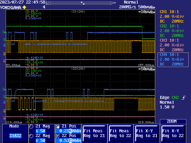
Here's a processing performance comparison between two different methods. The response is R1 from a CMD13 command. SD clock rate is sysclock/4.
Upper method is using a sync rx smartpin. The code, when transitioning from command to response, pauses the clock briefly to change over the pin mode and also drive the CMD pin high in preparation for detecting the responses start-bit. It then relies on real-time start-bit detection and bit-shifting to pick out the correct data as it's clocking in. It takes some extra time and clocks after the last bit is received before the processing is completed. This is marked by the termination of the clock gen a short time before the green trace is lowered. The final burst of clock pulses is a guard group added after completion.
Lower method is using an Fcached streamer block and the earlier mentioned P_PWM_SMPS clocking for start-bit search. It begins with the same command timing but instead of driving the CMD pin high it only needs to stop driving it because the smartpin search for the start-bit is happy to wait for the pin to rise on its pull-up. As can be seen the start-bit search takes extra time to complete and also transition back to sysclock/4 with the streamer all aligned. But this is made up for at the end by it's faster completion. And finally, the same guard group of clock pulses is added after completion.
End result is pretty much six of one and half a dozen of the other.
@evanh said:
End result is pretty much six of one and half a dozen of the other.
Yeah once you do the data transfer and find it swamps any minor speed difference here, you probably won't worry much about it in the end.
I do quite like this smartpin mode finding the start bit though, especially if it can leverage/share other pins for LEDs/card detect purposes etc. Seems cleaner to have the P2 HW do things for you and reduce the complexity in SW. Just have to make sure this CMD+RESP scheme can work in cleanly with the subsequent data transfers as well, particularly in cases with potential overlap (which I've not seen IRL). Remember that one COG can only stream from one given set of pins at a time.
@rogloh said:
... Just have to make sure this CMD+RESP scheme can work in cleanly with the subsequent data transfers as well, particularly in cases with potential overlap (which I've not seen IRL).
That's the minimum of 400 μs gap I've observed after the response. It seems safe to assume they never overlap even though the spec allows it.
@rogloh said:
I do quite like this smartpin mode finding the start bit though, especially if it can leverage/share other pins for LEDs/card detect purposes etc. Seems cleaner to have the P2 HW do things for you and reduce the complexity in SW.
There is one reason to use the smartpin-start-bit-search and streamer method over the bit-shifted smartpin method. It allows the response to be checked for tuning the streamer alignment since the streamer here is aligned in exactly the same way as the data block streamer code is.
Such an option allows to check every response CRC on the fly to figure if all is well or not. Therefore no house keeping unless a response CRC error has been detected. The alternative would be periodic checking or added overhead in front of a block read command to check its tuning first.
The third option would be to perform read data block CRCs but that is a heavy burden that I can't see being worth it simply because why are we pushing the performance envelop in the first place?
@rogloh said:
... Just have to make sure this CMD+RESP scheme can work in cleanly with the subsequent data transfers as well, particularly in cases with potential overlap (which I've not seen IRL).
That's the minimum of 400 μs gap I've observed after the response. It seems safe to assume they never overlap even though the spec allows it.
Based on what I saw too I tend to agree. Probably ok to just work with that until there is definitive proof of actual overlap with some real card.
@evanh said:
Such an option allows to check every response CRC on the fly to figure if all is well or not. Therefore no house keeping unless a response CRC error has been detected. The alternative would be periodic checking or added overhead in front of a block read command to check its tuning first.
Yeah that is handy if you want to keep input delay adaptive.
The third option would be to perform read data block CRCs but that is a heavy burden that I can't see being worth it simply because why are we pushing the performance envelop in the first place?
Yeah read CRCs should be optional due to their extra overhead which could slow things down too much if multiple sectors are desired to be read (ala streaming), and if you can determine input delay based on CMD+RESP feedback only that seems like a reasonable plan.
Hmm, I suspect, but haven't looked for real, that the existing SD SPI driver code in Flexspin is not sequencing a CMD12 correctly during a CMD18 multi-block read. It just does its command default of ten bytes timeout after the CMD12 and then gives up, deselecting the card anyway.
Since the CMD12 is being issued at the beginning of a block read, ten bytes would not even be close to enough to collect the actual response - which would be delivered after the block in progress. Given it obviously is working out in practice, I surmise this is likely because of card deselection cancelling the remaining sequence.
Oh, I misunderstood the diagram. I'd read it as CMD12 just needs to be earlier than the end of the block. Makes a lot more sense that the block rather terminates early because of CMD12.
Thanks for finding the info. I'm about to test doing the same in SD mode. CMD23 looks to be an alternative to CMD12 there though.
Well, I'm back to looking at this again. Finally put some effort into working out where stuff is placed in Eric's includes. I can now add a duplicate FAT+SD driver. So can make as big a mess as I like with experimental streamer driven 4-bit SD mode and still easily switch to the proven smartpin driven SPI mode to compare against. In fact should be able to use both together.
In the process I had a think about the pin order and decided on a more perfect one in future. It puts both SPI data pins right next to the clock pin. Cleans up the tricky smartpin clock routing issue.
    P0  =  POWER DOWN
    P1  =  ACTIVITY LED
    P2  =  COMMAND / DI
    P3  =  CLOCK
    P4  =  DAT0 / DO
    P5  =  DAT1
    P6  =  DAT2
    P7  =  DAT3 / CS
Yes @evanh I think that arrangement was also mentioned when we first found the issue with smartpin distances way back. But you then identified a work around in the meantime so the initial board could be used in SPI mode as well. Hopefully you can make progress in 4 bit mode in any case.
Note I'm currently working on other stuff now so haven't looked at this SD board for ages - I hope to fit a P2-Eval board in an old PVR case which has the full video port selection on the back (HDMI/VGA/Component/Composite/S-Video). Maybe I'll try to keep 8 IO pins free for my 4 bit SD breakout to be added, but it's far more tempting to allocate them to some PSRAM instead. Wish I could share some data pins for both options but it will mess with pin electrical loading so I think I'll have to use the on board SD reader if needed - and with its front panel now communicating with the P2 as of yesterday I am anticipating it should be possible to program it to power off the P2 from the front panel button if lockups ever occur due to SD loading on the flash data pin, or some other bad SD card state. The PVR case I'm talking about was shown here... https://forums.parallax.com/discussion/comment/1546391/#Comment_1546391
I do remember the jitter testing ... And still have no idea how to translate my scope work into a spec other than to say that the most stable measurements were more stable than what the scope could detect.
Hey @evanh , is your SD driver code for flexspin able to operate with disjoint IO pins allocated to the SD card? The reason I ask is that I only have two IO pins spare on my board and am tempted to make a separate SD interface and use a P2 Edge EC32MB with SPI flash on P58-P61 primarily for flash boot use but still share P59 (SD_DO) and P61 (SD_CLK) pins with this SD interface and use (say) P14 for SD_DI and P15 for SD_CS instead of P58 and P60 for the other SD pins. This way the on board SD card's 240 ohm inline resistor is not needed and in theory it might be simpler to share the pins without interference because CLK and CS don't have to toggle at the same time on the flash interface (flash CLK remains static during SD access). I just don't know if your code will like this or not...
Ok cool. Does the code differentiate between Smartpins vs bitbash use automatically based on pin allocation distances at init time, or do we need special builds or enable other options manually? Hopefully it "just works".
I've been pondering how best to handle the 4-bit mode. I guess this is the best reason to pursue using the streamer for command/response too, as well as data transfers.
The main reason I was tending toward using smartpins for command/response handling is because this then allows concurrent throughput of data alongside the command/response. But in reality, I have had my doubts about this idea because it'll burden the complexity of the driver. It's not like we're ever going to be implementing command queuing for example.
So streamer for everything seems best now.
@rogloh said:
Ok cool. Does the code differentiate between Smartpins vs bitbash use automatically based on pin allocation distances at init time, or do we need special builds or enable other options manually? Hopefully it "just works".
Currently it's just determined by Prop2 vs Prop1 build path. Prop1 gets bit-bashed, Prop2 gets smartpins.
I learnt, just the other day, that it's real simple to custom build via the includes just by adding a matching -D <label> to the Flexspin compile line. No different to doing it at top level. Ada dialled me in on it. Surprised me it was that simple.
So, a quick tweak of the sdmm.cc driver source to edit the build switch from being dependant on Prop1 vs Prop2 to instead using a custom #ifdef will get what you want. Or you can just block the switch and have only bit-bashed builds.
@rogloh said:
Ok cool. Does the code differentiate between Smartpins vs bitbash use automatically based on pin allocation distances at init time, or do we need special builds or enable other options manually? Hopefully it "just works".
Currently it's just determined by Prop2 vs Prop1 build path. Prop1 gets bit-bashed, Prop2 gets smartpins.
It'd be nicer if it was automatically determined based on allocated pin separation but that would of course increase the code size if you need both implementations to be present.
By the way here is the current schematic I'm working on, probably will start another thread once this gets going and I make up the actual board. Just need to figure out the SD card interface and whether or not I add Wifi (probably to P62,P63 via an ESP8266 or something simple). All the P2 pins are consumed now with just the two remaining for possible SD use. I added Midi ports so I could potentially turn this thing into a synth instrument one day (or at least experiment with Midi).


Comments
Yep, got that one going tonight ... But then went around in circles trying to work out why sysclock/4 gets stuck at the response. I've added a 400 kHz card init frequency - which works well but doesn't help the moment I switch to sysclock/4 after init. Tried adjusting phase of the command tx shifter, didn't help. Calling the same response routine as all the other commands. Adjusting sysclock frequency doesn't help. Not even a newly added general purpose timeout is tripping. It has me puzzled.
Will hook up the scope again tomorrow. I'd pulled it off a couple days back in preparation for boosting clock speed.
I can see myself moving to using the streamer for all CMD and DAT pins in the end. Whatever is going wrong with sysclock/4 will likely go away then. Not to mention that sysclock/2 is impossible with smartpins.
I reckon the smartpins are pretty good for the CMD/RESPONSE stuff as long as you run this phase a little slower before switching over to a faster data phase with the streamer. But the potential for overlap does complicate things. Maybe it just needs a special check when the DAT start bit arrives before the response on the smartpin has fully come in and then some manual clocking in that special case until the response is fully in and a reduction of the streamed data length after that in that case. Remember you can't stream from both the CMD and DAT sources at the same time from the same COG so one will need to be polled or a smartpin used.
Bah, too tired last night. I'd missed updating the source for a dynamic pin mode. It was still using the older compile time mode setting at SD command issuing. Therefore the phase shift setting wasn't being applied when switching to sysclock/4 config.
If I'd got the scope going earlier I'd have sorted it quicker. Another sign of tired I guess.
On a positive note, I wanted to add those features at some stage anyway.
sysclock/2 is pretty crazy performance for sure. Streamer timing is very sensitive though. The kicker here is different SD cards have different latencies so not really a goer without a dynamically calibrated compensation delay.
Adding a calibrate sequence to a failed response CRC should be doable without creating additional overhead ... well at least not on block read/write anyway. Question is, is that really enough checking when forever teetering on the edge like this? Checking the data block CRC as well would provide a lot more security.
Yeah checking data CRC on reads could be a good thing for ensuring integrity and this would be okay with just single sector reads, but streaming data in at the same time using multiple sector reads at higher speeds may be hard to keep up unless you could find a way to use the COG to compute it while streaming somehow.
We would need a data CRC for writes so some tight CRC code will need to be figured out regardless.
Think your comment below from the flexspin compiler thread belongs here...
I can't recall the clock speed I ran for the CMD/RESP smart pin but I know didn't see any timing issues when running my data data phase up to sysclk/2 using the streamer although the P2 frequency I was running at might have nicely been in a sweet spot range for the input delay window. I know you can't clock the sync rx smartpin mode too fast or it won't detect input pin clock transitions correctly (something less than sysclk/2 is required). I was certainly running the clock fast only for the DAT pin transfers and somewhat slower for the CMD/RESP transfer and I know I was doing simple pin polling for the start bit vs what you do with that special SMPS smartpin mode that is also looking for a change on the pin while running. If that works l do like your solution.
In general though I don't think you have to optimize the CMD/RESP stuff down to saving every last clock to get the best bang per buck with SD cards, it's the data transfer phase sending 512 bytes that needs to be fast, although speeding up the start bit checking is a good thing which is where my own code would have been somewhat slower that what you are doing. Ultimately supporting multiple SD sector reads will be where it will really fly and stream back data super fast off a decent SD card. By that point the limiting factor is probably just some CRC validation should you wish to enable it, it's probably best to make that optional on reads.
That was me clarifying that my earlier post about a possible Flexspin bug was likely just my own buggy code.
In fact I should add to it that the historical issue I referenced in there has a decent probability of being the same problem - Sync serial smartpins not seeing every clock pulse can lead to puzzling behaviour.
As for minimum ratio, the smartpin needs sampling time to identify individually both the low phase and high phase of each clock pulse:
- Sysclock/4 is it when the Prop2 is the clock master. In theory this could be smaller but then the phase timing has to be calibrated. I don't know this for sure. See below.
As for why I end up in these situations. I like to interleave functionality when optimising this stuff, so can blow up what was a perfectly okay piece of code.
Bah! My rx smartpin code might be too slow for sysclock/3 ... Yeah, I'd discovered that in the past but forgot about it. I'm not stopping the clock at the response start-bit detection - which adds bit-shift processing complexity - which I'm real-time dealing with.
Like you say, no need to be pushing the command and response clock rate anyway.
It seems to be a little of both. Every card model seems to need a delay after response followed by a set amount of preamble clocks (different for different models) before it sends the first data block. The minimum delay is as yet unknown - Empirically, 400 μs for first block, but is longer on some cards. So, nothing like the spec looks.
This arrangement has a nice side effect - it means a small number trailing clock pulses post-response aren't counted toward the data block preamble. Therefore they can be blindly added after the response as is required for any command completion.
Here's a processing performance comparison between two different methods. The response is R1 from a CMD13 command. SD clock rate is sysclock/4.
Upper method is using a sync rx smartpin. The code, when transitioning from command to response, pauses the clock briefly to change over the pin mode and also drive the CMD pin high in preparation for detecting the responses start-bit. It then relies on real-time start-bit detection and bit-shifting to pick out the correct data as it's clocking in. It takes some extra time and clocks after the last bit is received before the processing is completed. This is marked by the termination of the clock gen a short time before the green trace is lowered. The final burst of clock pulses is a guard group added after completion.
Lower method is using an Fcached streamer block and the earlier mentioned
P_PWM_SMPSclocking for start-bit search. It begins with the same command timing but instead of driving the CMD pin high it only needs to stop driving it because the smartpin search for the start-bit is happy to wait for the pin to rise on its pull-up. As can be seen the start-bit search takes extra time to complete and also transition back to sysclock/4 with the streamer all aligned. But this is made up for at the end by it's faster completion. And finally, the same guard group of clock pulses is added after completion.End result is pretty much six of one and half a dozen of the other.
Yeah once you do the data transfer and find it swamps any minor speed difference here, you probably won't worry much about it in the end.
I do quite like this smartpin mode finding the start bit though, especially if it can leverage/share other pins for LEDs/card detect purposes etc. Seems cleaner to have the P2 HW do things for you and reduce the complexity in SW. Just have to make sure this CMD+RESP scheme can work in cleanly with the subsequent data transfers as well, particularly in cases with potential overlap (which I've not seen IRL). Remember that one COG can only stream from one given set of pins at a time.
That's the minimum of 400 μs gap I've observed after the response. It seems safe to assume they never overlap even though the spec allows it.
There is one reason to use the smartpin-start-bit-search and streamer method over the bit-shifted smartpin method. It allows the response to be checked for tuning the streamer alignment since the streamer here is aligned in exactly the same way as the data block streamer code is.
Such an option allows to check every response CRC on the fly to figure if all is well or not. Therefore no house keeping unless a response CRC error has been detected. The alternative would be periodic checking or added overhead in front of a block read command to check its tuning first.
The third option would be to perform read data block CRCs but that is a heavy burden that I can't see being worth it simply because why are we pushing the performance envelop in the first place?
Based on what I saw too I tend to agree. Probably ok to just work with that until there is definitive proof of actual overlap with some real card.
Yeah that is handy if you want to keep input delay adaptive.
Yeah read CRCs should be optional due to their extra overhead which could slow things down too much if multiple sectors are desired to be read (ala streaming), and if you can determine input delay based on CMD+RESP feedback only that seems like a reasonable plan.
Hmm, I suspect, but haven't looked for real, that the existing SD SPI driver code in Flexspin is not sequencing a CMD12 correctly during a CMD18 multi-block read. It just does its command default of ten bytes timeout after the CMD12 and then gives up, deselecting the card anyway.
Since the CMD12 is being issued at the beginning of a block read, ten bytes would not even be close to enough to collect the actual response - which would be delivered after the block in progress. Given it obviously is working out in practice, I surmise this is likely because of card deselection cancelling the remaining sequence.
IIRC CMD12 cuts off any blocks in progress (at least in SPI mode)
Infact,
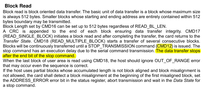
Oh, I misunderstood the diagram. I'd read it as CMD12 just needs to be earlier than the end of the block. Makes a lot more sense that the block rather terminates early because of CMD12.
Thanks for finding the info. I'm about to test doing the same in SD mode. CMD23 looks to be an alternative to CMD12 there though.
Well, I'm back to looking at this again. Finally put some effort into working out where stuff is placed in Eric's includes. I can now add a duplicate FAT+SD driver. So can make as big a mess as I like with experimental streamer driven 4-bit SD mode and still easily switch to the proven smartpin driven SPI mode to compare against. In fact should be able to use both together.
In the process I had a think about the pin order and decided on a more perfect one in future. It puts both SPI data pins right next to the clock pin. Cleans up the tricky smartpin clock routing issue.
P0 = POWER DOWN P1 = ACTIVITY LED P2 = COMMAND / DI P3 = CLOCK P4 = DAT0 / DO P5 = DAT1 P6 = DAT2 P7 = DAT3 / CSYes @evanh I think that arrangement was also mentioned when we first found the issue with smartpin distances way back. But you then identified a work around in the meantime so the initial board could be used in SPI mode as well. Hopefully you can make progress in 4 bit mode in any case.
Note I'm currently working on other stuff now so haven't looked at this SD board for ages - I hope to fit a P2-Eval board in an old PVR case which has the full video port selection on the back (HDMI/VGA/Component/Composite/S-Video). Maybe I'll try to keep 8 IO pins free for my 4 bit SD breakout to be added, but it's far more tempting to allocate them to some PSRAM instead. Wish I could share some data pins for both options but it will mess with pin electrical loading so I think I'll have to use the on board SD reader if needed - and with its front panel now communicating with the P2 as of yesterday I am anticipating it should be possible to program it to power off the P2 from the front panel button if lockups ever occur due to SD loading on the flash data pin, or some other bad SD card state. The PVR case I'm talking about was shown here... https://forums.parallax.com/discussion/comment/1546391/#Comment_1546391
Damn, I don't remember any of those photos! O_o
I do remember the jitter testing ... And still have no idea how to translate my scope work into a spec other than to say that the most stable measurements were more stable than what the scope could detect.
Hey @evanh , is your SD driver code for flexspin able to operate with disjoint IO pins allocated to the SD card? The reason I ask is that I only have two IO pins spare on my board and am tempted to make a separate SD interface and use a P2 Edge EC32MB with SPI flash on P58-P61 primarily for flash boot use but still share P59 (SD_DO) and P61 (SD_CLK) pins with this SD interface and use (say) P14 for SD_DI and P15 for SD_CS instead of P58 and P60 for the other SD pins. This way the on board SD card's 240 ohm inline resistor is not needed and in theory it might be simpler to share the pins without interference because CLK and CS don't have to toggle at the same time on the flash interface (flash CLK remains static during SD access). I just don't know if your code will like this or not...
The original bit-bashed code path will do that, slowly of course. My code uses smartpins and therefore needs the clock pin nearby the data pins.
Ok cool. Does the code differentiate between Smartpins vs bitbash use automatically based on pin allocation distances at init time, or do we need special builds or enable other options manually? Hopefully it "just works".
I've been pondering how best to handle the 4-bit mode. I guess this is the best reason to pursue using the streamer for command/response too, as well as data transfers.
The main reason I was tending toward using smartpins for command/response handling is because this then allows concurrent throughput of data alongside the command/response. But in reality, I have had my doubts about this idea because it'll burden the complexity of the driver. It's not like we're ever going to be implementing command queuing for example.
So streamer for everything seems best now.
Currently it's just determined by Prop2 vs Prop1 build path. Prop1 gets bit-bashed, Prop2 gets smartpins.
I learnt, just the other day, that it's real simple to custom build via the includes just by adding a matching
-D <label>to the Flexspin compile line. No different to doing it at top level. Ada dialled me in on it. Surprised me it was that simple.So, a quick tweak of the sdmm.cc driver source to edit the build switch from being dependant on Prop1 vs Prop2 to instead using a custom #ifdef will get what you want. Or you can just block the switch and have only bit-bashed builds.
It'd be nicer if it was automatically determined based on allocated pin separation but that would of course increase the code size if you need both implementations to be present.
By the way here is the current schematic I'm working on, probably will start another thread once this gets going and I make up the actual board. Just need to figure out the SD card interface and whether or not I add Wifi (probably to P62,P63 via an ESP8266 or something simple). All the P2 pins are consumed now with just the two remaining for possible SD use. I added Midi ports so I could potentially turn this thing into a synth instrument one day (or at least experiment with Midi).