C-class is a worthless measure nowadays, it only goes up to 10, which any remorely acceptable card will easily handle. Check U class, that goes up to 3 (= 30MB/s). No idea why they changed the symbol. V class goes even higher, but iirc consistent throughput is only guranteed when using the special video recording commands.
A class concerns latency of random access, btw. Any A class also implies C10.
@Wuerfel_21 said:
C-class is a worthless measure nowadays, it only goes up to 10, which any remorely acceptable card will easily handle. Check U class, that goes up to 3 (= 30MB/s).
It's weird, the micro SD card I used has C10 printed on it and the Roman "I" numeral implying support for UHS-1 104MB/s bus speed operation, but doesn't have any U rating printed on it. It must have been an earlier one as they were transitioning over to that rating scheme, as it's only 16GB and SDHC, not the newer SDXC which may explain why.
@evanh Just been hunting around on my old machine this morning and can't find it in the normal place I keep my P2 code. I wonder if it was somehow stored in my overflowing Downloads area which I aggressively cleaned out recently in preparation for migration of files to a new Mac (I've a bad habit of starting out test code ideas there from other things I download). This was one of the latest things I worked on before moving to this new machine so it's unlikely to be backed up too unfortunately... will keep looking for a bit longer on a few SD cards or USB sticks I have laying about but not sure what I'll find right now.
In any case it wasn't a lot of code and only took a couple of days of messing about to get something working. It could only send commands and read sectors. Hadn't got as far as writes. I do recall that the tricky bit was the CRC stuff which I think was covered in some posts here. The rest can be gleaned from probing the signals a bit and reading what you find online about the state machine stuff to enable cards transfers (just a few setup commands as I recall). It's just half duplex on the CMD line using sync serial and the streamer could be used for the 4 bit DAT bus. I think I had to split the 48 bit CMD stuff into two transfers to send it out in two 24 bit halves.
In future I really have to be more diligent in tracking my test code. It can feel a bit scattered to the winds right now, especially during this migration which is still incomplete. I think using GitHub again is probably the way to go, but as this P2 stuff is really just a hobby these days in some ways I don't want to make myself feel like it's all "work" again by strictly following the proper software engineering techniques like I used to do in my career. That could quickly become a turn off when messing about with ideas. Probably could be some laziness creeping in as we age.
Bugger, sounds like I'm a couple of weeks late asking.
No biggie, I was more interested in the sequence of SD commands you used and any condition testing of results. Standard SD protocol is definitely different to the SD-SPI protocol. That and how you structured the CMD and DAT timings, which is also different.
@evanh said:
Bugger, sounds like I'm a couple of weeks late asking.
Nah, file cleanout happened a couple of months ago when I got a new machine. I've been setting up a nice new hardware environment lately and not really working on software right now, so final code cleanup/migration is still tbd. General desk tidiness got right out of hand during our extended covid lockdown and cables and other things were just strewn everywhere before. I've got 4 monitors and two laptop screens to manage so you can imagine the mess. It's funny how lots of physical clutter can make you feel hemmed in mentally too when working on things. But it's finally improving now and I'm getting a much better/healthier environment to develop and test code again.
No biggie, I was more interested in the sequence of SD commands you used and any condition testing of results. Standard SD protocol is definitely different to the SD-SPI protocol. That and how you structured the CMD and DAT timings, which is also different.
Yeah for that sort of thing you'll probably need to dig into the (simplified) sd specs which are available online and look for other projects that initialize cards etc. That's pretty much the path I took (along with some reverse engineering of clock/data signals with a logic analyzer to get the P2 timing right and help figure out the CRC bit order etc). I remember you need to initialize and "select" the card for data transfers. I think there was an extra 4 bit mode enable command somewhere too but I'd need to see the code again to be 100% sure.
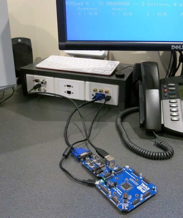
Related to tidiness, one thing I've done recently which has made a huge difference was to build a small patch panel console thing using basic wallplates to let me access monitor inputs and USB ports and audio sources for devices under test. If you use much shorter cables you can keep your desk tidy. Before this I had to mess about and change monitor inputs and recable each time I wanted to test something new etc and it quickly gets out of hand like that. I also now use a VGA KVM and distribution amp as well as an HDMI switch so it's become far more flexible and all cables are hidden from view behind this box down the back of the desk out of sight. @Tubular kindly helped bevel cut the matching laminate.
Yep, I got the typical total mess. Two messy desks on opposite sides of the room with an extended USB cable draped across the floor. And boxes that should be stored, still on the floor too.
Yep, I got the typical total mess. Two messy desks on opposite sides of the room with an extended USB cable draped across the floor. And boxes that should be stored, still on the floor too.
Sounds like me from a couple of weeks ago. My other electronics/assembly desk behind me is still bad too. That one is still on the list but will take longer to refit. Trying to figure out the best way to set it up the way in which I mostly use it and a way I will be able to keep it tidy (if even possible).
Ha Ha! Mine too; boxes, draping cables, organised chaos
And the desk behind- also a picasso effort - With regular use on ever changing projects it seems "tidy" is not possible in any economic way. Just gotta embrace and love it !
I'm making progress at last ... Took me a few attempts at the problem to realised that CMD0 doesn't ever respond in SD mode. And that CMD3 also doesn't respond until "identity" state is entered first. It wasn't until I was testing with CMD8 that I was able to start debugging things!
Yeah you get different responses depending on the command type and their lengths can vary between 0,48,136 bits. I think the main setup commands of interest are probably these ones...
CMD0 - reset
CMD8 - voltage check
ACMD41 - sdhc init
CMD2 - gets the cid
CMD3 - gets the rca
CMD7 - selects the card before you can read or write it (puts it into a "transfer" state where you can read or write it)
ACMD6 - 4 bit mode
CMD6 - 50MHz mode
And no command responds when not already in a suitable state for that command - and since "idle" state only supports a few commands - of which CMD0 never has a response anyway ... That made it trickier than I was expecting to get started on debugging the basic routines. It definitely caught me off guard.
Had to do some reading first ...
EDIT: Damn, CRC in the responses are a muddle. R3 responses don't have a CRC, and R2 responses have it offset by one bit! or not ... ah, it looks like ACMD41 is the only one that has R3 responses ... still can't see why the CRC field of R3 is not used, though.
@evanh said:
EDIT: Damn, CRC in the responses are a muddle. R3 responses don't have a CRC, and R2 responses have it offset by one bit! or not ... ah, it looks like ACMD41 is the only one that has R3 responses ... still can't see why the CRC field of R3 is not used, though.
LOL. getting a little dejavu. I must have hit the exact same issues.
okay, I'm stumped. Mostly not doing much branching on checks, and am getting expected behaviour until it comes to moving from "standby" to "transfer" state with a CMD7. The R1 response indicates it is staying in standby. Subsequent commands then don't respond ... ah, on that note, I guess it's time to implement a response timeout mechanism ...
Oops, maybe nothing is wrong, just the R1 response wasn't as expected. Trying a valid command for transfer state, after the CMD7, does work. And that then responds with R1 = $900.
LOL, duh, right there in that snapshot of the datasheet. Okay, so maybe not the case for other statuses. Something to pay attention to as I build more of the code. Thanks for the nudge.
I've solved the CRC discrepancy in the R2 responses. It's because the CRC does not cover the whole of R2 but just the CID or CSD component of R2. ie: doesn't include the first byte of response ... Just another oddity.
Next up: The spec seems to say that a v1.x interface is adopted by not using CMD8 ... but the card I'm testing with never comes ready when looping on ACMD41 without the initial CMD8. And when ignoring the ready check I just get a pile of subsequent timeouts - indicating the card has stayed in "idle" state.
So, I guess then that late model cards won't accept operating on a v1.x interface.
Yup, that has worked fine already. I'm just backtracking a little and checking the alleyways with the 64 clock timeout now functioning. I like doing the same in games funnily.
Cool, seems you are getting closer at least. Once the card is fully initialized and you've got the CRC stuff nailed you should make good progress experimenting.
Ah, I note the response timeout details are not in the simplified spec. They're in section 4.12.
I managed to google a copy of the full spec a couple of years back. Not too surprisingly, every page is watermarked with the purchaser's name.
There's a lot of leeway in the spec for Default Speed clock to data phase relationship. The 14 ns latency limit is well beyond the 10 ns rising clock edge. That just wouldn't work if it was really that far off. In reality, modern cards at least, are going to be 2 to 3 ns. Maybe 5 ns for old cards.
High Speed spec has the phase shifted, as we've observed - So that's an official trick then! I guess the cards that didn't do it for me had not switched to High Speed for whatever reason. Maybe because not supported in SPI mode that I was testing in at the time.
At any rate, the 14 ns is phased shifted to allow improved alignment with the rising clock edge. Using this with clock idling high might not be as desirable ... something to experiment on ...
EDIT: There's not really any difference for the Prop2. Either way we still have to tune the Prop2's own I/O latency ... so any phase shift from the SD card is just an offset to that existing tuning parameter. It's probably easier to continue ignoring SD High Speed mode.
Doh, every step is a stumble still. Just found out that ACMD's CMD55 prefixing actually uses the RCA value which, up till now, had been zero. But, now in transfer mode, I need to feed it the established value ... One more fix.
I'd been using the RCA already with non-ACMD's but the CMD55 prefixing for ACMD was automated in a subroutine and did not have access to the RCA. ACMD41 uses zero for RCA, but ACMD6 later on needs the established RCA value. I've now moved RCA out as a global variable so I don't have to pass it via function parameters for this.
Maybe I'll ditch the automatic prefixing instead. It looks like ACMD is used only twice anyway.
And to make it crystal clear someone has built an extensive table that lists both the "normal" and "reverse" polynomial constants for a wide range of CRCs.
So now I know the Prop2's CRCNIB uses the reasonably common "reverse" representation verbatim.
Comments
C-class is a worthless measure nowadays, it only goes up to 10, which any remorely acceptable card will easily handle. Check U class, that goes up to 3 (= 30MB/s). No idea why they changed the symbol. V class goes even higher, but iirc consistent throughput is only guranteed when using the special video recording commands.
A class concerns latency of random access, btw. Any A class also implies C10.
It's weird, the micro SD card I used has C10 printed on it and the Roman "I" numeral implying support for UHS-1 104MB/s bus speed operation, but doesn't have any U rating printed on it. It must have been an earlier one as they were transitioning over to that rating scheme, as it's only 16GB and SDHC, not the newer SDXC which may explain why.
Roger,
Can you dig up the final code you wrote for this board please. I want to make a start on supporting it in Flexspin.
@evanh Just been hunting around on my old machine this morning and can't find it in the normal place I keep my P2 code. I wonder if it was somehow stored in my overflowing Downloads area which I aggressively cleaned out recently in preparation for migration of files to a new Mac (I've a bad habit of starting out test code ideas there from other things I download). This was one of the latest things I worked on before moving to this new machine so it's unlikely to be backed up too unfortunately... will keep looking for a bit longer on a few SD cards or USB sticks I have laying about but not sure what I'll find right now.
In any case it wasn't a lot of code and only took a couple of days of messing about to get something working. It could only send commands and read sectors. Hadn't got as far as writes. I do recall that the tricky bit was the CRC stuff which I think was covered in some posts here. The rest can be gleaned from probing the signals a bit and reading what you find online about the state machine stuff to enable cards transfers (just a few setup commands as I recall). It's just half duplex on the CMD line using sync serial and the streamer could be used for the 4 bit DAT bus. I think I had to split the 48 bit CMD stuff into two transfers to send it out in two 24 bit halves.
In future I really have to be more diligent in tracking my test code. It can feel a bit scattered to the winds right now, especially during this migration which is still incomplete. I think using GitHub again is probably the way to go, but as this P2 stuff is really just a hobby these days in some ways I don't want to make myself feel like it's all "work" again by strictly following the proper software engineering techniques like I used to do in my career. That could quickly become a turn off when messing about with ideas. Probably could be some laziness creeping in as we age.
Bugger, sounds like I'm a couple of weeks late asking.
No biggie, I was more interested in the sequence of SD commands you used and any condition testing of results. Standard SD protocol is definitely different to the SD-SPI protocol. That and how you structured the CMD and DAT timings, which is also different.
Nah, file cleanout happened a couple of months ago when I got a new machine. I've been setting up a nice new hardware environment lately and not really working on software right now, so final code cleanup/migration is still tbd. General desk tidiness got right out of hand during our extended covid lockdown and cables and other things were just strewn everywhere before. I've got 4 monitors and two laptop screens to manage so you can imagine the mess. It's funny how lots of physical clutter can make you feel hemmed in mentally too when working on things. But it's finally improving now and I'm getting a much better/healthier environment to develop and test code again.
Yeah for that sort of thing you'll probably need to dig into the (simplified) sd specs which are available online and look for other projects that initialize cards etc. That's pretty much the path I took (along with some reverse engineering of clock/data signals with a logic analyzer to get the P2 timing right and help figure out the CRC bit order etc). I remember you need to initialize and "select" the card for data transfers. I think there was an extra 4 bit mode enable command somewhere too but I'd need to see the code again to be 100% sure.
Related to tidiness, one thing I've done recently which has made a huge difference was to build a small patch panel console thing using basic wallplates to let me access monitor inputs and USB ports and audio sources for devices under test. If you use much shorter cables you can keep your desk tidy. Before this I had to mess about and change monitor inputs and recable each time I wanted to test something new etc and it quickly gets out of hand like that. I also now use a VGA KVM and distribution amp as well as an HDMI switch so it's become far more flexible and all cables are hidden from view behind this box down the back of the desk out of sight. @Tubular kindly helped bevel cut the matching laminate.
Fancy!
Yep, I got the typical total mess. Two messy desks on opposite sides of the room with an extended USB cable draped across the floor. And boxes that should be stored, still on the floor too.
Sounds like me from a couple of weeks ago. My other electronics/assembly desk behind me is still bad too. That one is still on the list but will take longer to refit. Trying to figure out the best way to set it up the way in which I mostly use it and a way I will be able to keep it tidy (if even possible).
Ha Ha! Mine too; boxes, draping cables, organised chaos
And the desk behind- also a picasso effort - With regular use on ever changing projects it seems "tidy" is not possible in any economic way. Just gotta embrace and love it !
I'm making progress at last ... Took me a few attempts at the problem to realised that CMD0 doesn't ever respond in SD mode. And that CMD3 also doesn't respond until "identity" state is entered first. It wasn't until I was testing with CMD8 that I was able to start debugging things!
Yeah you get different responses depending on the command type and their lengths can vary between 0,48,136 bits. I think the main setup commands of interest are probably these ones...
CMD0 - reset
CMD8 - voltage check
ACMD41 - sdhc init
CMD2 - gets the cid
CMD3 - gets the rca
CMD7 - selects the card before you can read or write it (puts it into a "transfer" state where you can read or write it)
ACMD6 - 4 bit mode
CMD6 - 50MHz mode
And no command responds when not already in a suitable state for that command - and since "idle" state only supports a few commands - of which CMD0 never has a response anyway ... That made it trickier than I was expecting to get started on debugging the basic routines. It definitely caught me off guard.
Had to do some reading first ...
EDIT: Damn, CRC in the responses are a muddle. R3 responses don't have a CRC, and R2 responses have it offset by one bit! or not ... ah, it looks like ACMD41 is the only one that has R3 responses ... still can't see why the CRC field of R3 is not used, though.
LOL. getting a little dejavu. I must have hit the exact same issues.
okay, I'm stumped. Mostly not doing much branching on checks, and am getting expected behaviour until it comes to moving from "standby" to "transfer" state with a CMD7. The R1 response indicates it is staying in standby. Subsequent commands then don't respond ... ah, on that note, I guess it's time to implement a response timeout mechanism ...
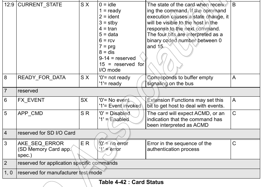
$520 is "ident" + "ready" + "app enabled"
$700 is "standby" + "ready"
For "tran" + "ready" it should be $900
Relevant R1 status bits:
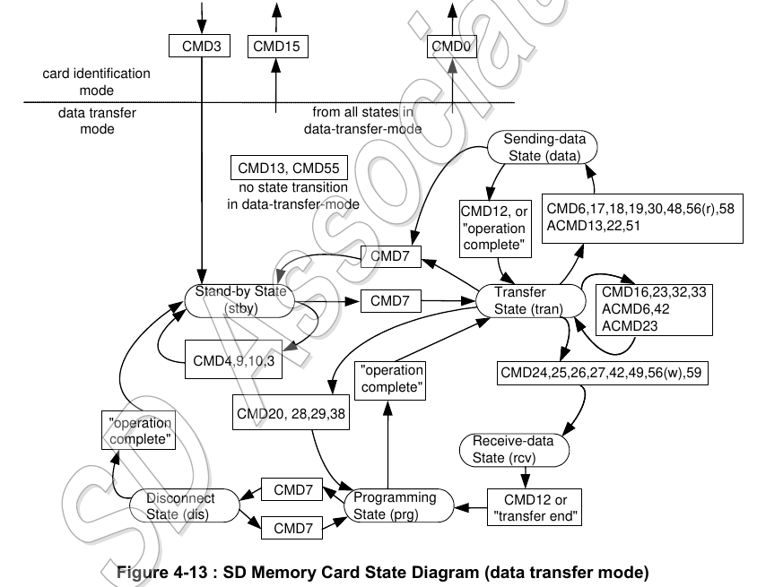
Oops, maybe nothing is wrong, just the R1 response wasn't as expected. Trying a valid command for transfer state, after the CMD7, does work. And that then responds with R1 = $900.
So, I guess that means that responses tend to report the SD card's status prior to the issued command being executed.
That’s how I read the note against bits 12:9 in the response bits table.
LOL, duh, right there in that snapshot of the datasheet. Okay, so maybe not the case for other statuses. Something to pay attention to as I build more of the code. Thanks for the nudge.
No problem. Sometimes we just need to show it to someone else to see what’s right there in front of us :-)
I've solved the CRC discrepancy in the R2 responses. It's because the CRC does not cover the whole of R2 but just the CID or CSD component of R2. ie: doesn't include the first byte of response ... Just another oddity.
Next up: The spec seems to say that a v1.x interface is adopted by not using CMD8 ... but the card I'm testing with never comes ready when looping on ACMD41 without the initial CMD8. And when ignoring the ready check I just get a pile of subsequent timeouts - indicating the card has stayed in "idle" state.
So, I guess then that late model cards won't accept operating on a v1.x interface.
You need to set a bit in ACMD41 I think to enable the SDHC/SDXC stuff.
Yup, that has worked fine already. I'm just backtracking a little and checking the alleyways with the 64 clock timeout now functioning. I like doing the same in games funnily.
Cool, seems you are getting closer at least. Once the card is fully initialized and you've got the CRC stuff nailed you should make good progress experimenting.
Ah, I note the response timeout details are not in the simplified spec. They're in section 4.12.
I managed to google a copy of the full spec a couple of years back. Not too surprisingly, every page is watermarked with the purchaser's name.
There's a lot of leeway in the spec for Default Speed clock to data phase relationship. The 14 ns latency limit is well beyond the 10 ns rising clock edge. That just wouldn't work if it was really that far off. In reality, modern cards at least, are going to be 2 to 3 ns. Maybe 5 ns for old cards.
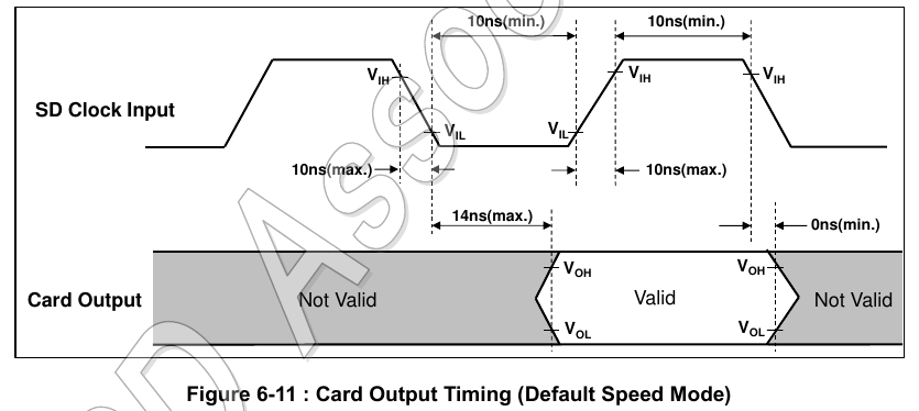
High Speed spec has the phase shifted, as we've observed - So that's an official trick then! I guess the cards that didn't do it for me had not switched to High Speed for whatever reason. Maybe because not supported in SPI mode that I was testing in at the time.
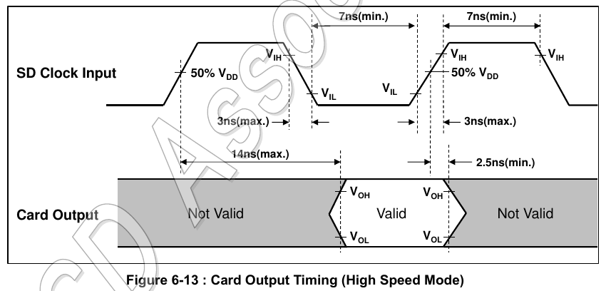
At any rate, the 14 ns is phased shifted to allow improved alignment with the rising clock edge. Using this with clock idling high might not be as desirable ... something to experiment on ...
EDIT: There's not really any difference for the Prop2. Either way we still have to tune the Prop2's own I/O latency ... so any phase shift from the SD card is just an offset to that existing tuning parameter. It's probably easier to continue ignoring SD High Speed mode.
Doh, every step is a stumble still. Just found out that ACMD's CMD55 prefixing actually uses the RCA value which, up till now, had been zero. But, now in transfer mode, I need to feed it the established value ... One more fix.
Yeah you get that rca value from CMD3. Gotta wade through all the available info. But you must be getting close now to data transfers...
I'd been using the RCA already with non-ACMD's but the CMD55 prefixing for ACMD was automated in a subroutine and did not have access to the RCA. ACMD41 uses zero for RCA, but ACMD6 later on needs the established RCA value. I've now moved RCA out as a global variable so I don't have to pass it via function parameters for this.
Maybe I'll ditch the automatic prefixing instead. It looks like ACMD is used only twice anyway.
I've been adding comments to the source code. In particular, adding SD spec section numbers where there is hard coded values like the timeouts.
In my searches I found Wikipedia's page on CRC good reading. Better than usual, IMHO. It details the various differing, and confusing, ways the polynomial constants are represented - https://en.wikipedia.org/wiki/Cyclic_redundancy_check#Specification
And to make it crystal clear someone has built an extensive table that lists both the "normal" and "reverse" polynomial constants for a wide range of CRCs.
So now I know the Prop2's CRCNIB uses the reasonably common "reverse" representation verbatim.