rxlag matching between routines isn't entirely sorted when High-Speed access mode is engaged. (This is likely affecting other issues.)
The Adata card, my oldest uSD card, and the newer of the two SanDisk cards are timing out on CMD7 SELECT when High-Speed is engaged. (Haven't looked into this at all.) Solved with P_INVERT_OUTPUT bug fix.
The Adata wasn't happy with sysclock/2 and 120 MHz Default-Speed either. EDIT: Okay, this one looks like our old friend from HyperRAM days. It's okay at both SD clock of 115 MHz (rxlag=7) and 125 MHz (rxlag=8). So probably wise to cap all future clocks at 100 MHz. >100 MHz wasn't looking effective generally anyway.
When in High-Speed access mode, both the older Sandisk card and the Samsung card have to calibrate rxlag twice before they settle. They seem happy otherwise. It's like they aren't actually changing access mode immediately. (Not that I've looked closely.) Solved with P_INVERT_OUTPUT bug fix.
UPDATE: Right, fixed two with one stone: Part of making the High-Speed mode changes function cleanly was to revert the SD clock back to positive polarity. For Default-Speed I'd had P_INVERT_OUTPUT applied to the clock pin. ... Well, I'd failed to thoroughly apply the reversion to all the needed parts of the source code. There is a lot places where the clock smartpin is reconfigured. Each one reapplies the inversion or not.
Well, I've been running the combinations and am now settling on using P_PULSE for clock gen. Even though it creates a little more bloat when adjusting the clock divider, it has its advantages. I hadn't used P_TRANSITION very much and thought I better actually compare them.
It turns out there is a notable advantage with the start-bit search, of both the command response and data blocks, where P_PULSE can be operated at double the rate of P_TRANSITION. (A little clarification: I've also decided that I want to avoid using input redirection so then no restrictions of where each pin is assigned. This means that the P_PWM_SMPS smartpin mode is off limits for the start-bit search.)
With P_PULSE, the streamer lead-in is computed to a whole SD clock cycle after DIRH, but with P_TRANSITION this is a half-cycle instead. That whole cycle available to the lead-in can be taken advantage of by shifting the streamer's first sample ahead of the first clock pulse gen. Ie: Read in the already present response's T bit, or first data bit, that has been presented by an overclocked start-bit search.
Another advantage of P_PULSE is it can handle sysclock/3. And that is actually a nice divider to use. It has the same rx sampling reliability that sysclock/4 has. Adjusting rxlag to align with the centre slot is hugely better than having to pick from two questionable sample points with sysclock/2.
That said, I guess making use of pin registration like we did with HyperRAM helps alleviate this at sysclock/2. It's something still to be investigated. It may have a negative impact on the above start-bit searching speed.
I've learnt that the Sandisk cards will go faster than 50 MB/s. They also have the worst latencies generally.
None of the others will though. Those others just add extra latency to make any SD clock rate above about 110 MHz ineffective.
I'm thinking of settling on sysclock/2 for sysclocks up to 200 MHz. Above that use sysclock/3. Keeps the decision tree small and will still give ridiculously high performance.
So with your start bit search approach, how much time is wasted now after after the start bit actually occurs? IMO I don't think it really has to be 100% optimal for command transfers, given the larger percentage of time allotted to the data transfer itself vs overall time of entire transfer and its outer CMD transaction. For data it does need to be fast in order to respond in time.
As to sysclk/2 vs sysclk/3 I know I was still able to get sysclk/2 transfer rates working at high P2 speeds though perhaps I just was lucky with my choice of card - it should be documented somewhere earlier in this thread... here it was: https://forums.parallax.com/discussion/comment/1545820/#Comment_1545820
@rogloh said:
So with your start bit search approach, how much time is wasted now after after the start bit actually occurs? IMO I don't think it really has to be 100% optimal for command transfers, given the larger percentage of time allotted to the data transfer itself vs overall time of entire transfer and its outer CMD transaction. For data it does need to be fast in order to respond in time.
Each block also has the same search. It definitely impacts throughput. I report both bulk data and command/response performances now, in a bulk repeating manner, to gauge which combinations of methods fit together.
As to sysclk/2 vs sysclk/3 I know I was still able to get sysclk/2 transfer rates working at high P2 speeds though perhaps I just was lucky with my choice of card - it should be documented somewhere earlier in this thread... here it was: https://forums.parallax.com/discussion/comment/1545820/#Comment_1545820
It's definitely card dependant. My oldest card, the Adata, struggles above 100 MHz SD clock.
@evanh said:
Each block also has the same search. It definitely impacts throughput. I report both bulk data and command/response performances now, in a bulk repeating manner, to gauge which combinations of methods fit together.
Command/response runs for one card (Kingston) at one clock rate (40 MHz sysclock, 20 MHz SD clock):
  - Response handler #3
  - Multi-block-read loop
  - CRC before block-read
  - P_PULSE clock-gen
 Response-test duration = 28100 us

  - Response handler #3
  - Multi-block-read loop
  - CRC during block-read
  - P_PULSE clock-gen
 Response-test duration = 28000 us

  - Response handler #4
  - Multi-block-read loop
  - CRC during block-read
  - P_PULSE clock-gen
 Response-test duration = 30500 us

  - Response handler #2
  - Multi-block-read loop
  - CRC during block-read
  - P_PULSE clock-gen
 Response-test duration = 28700 us

  - Response handler #2
  - Multi-block-read loop
  - CRC during block-read
  - P_TRANSITION clock-gen
 Response-test duration = 30000 us

  - Response handler #2
  - Single-block-read loop
  - CRC before block-read
  - P_TRANSITION clock-gen
 Response-test duration = 30100 us

 - Response handler #3
  - Multi-block-read loop
  - CRC during block-read
  - P_TRANSITION clock-gen
 Response-test duration = 27700 us

  - Response handler #3
  - Multi-block-read loop
  - CRC before block-read
  - P_TRANSITION clock-gen
 Response-test duration = 28000 us

  - Response handler #3
  - Single-block-read loop
  - CRC before block-read
  - P_TRANSITION clock-gen
 Response-test duration = 27800 us

  - Response handler #3
  - Single-block-read loop
  - CRC during block-read
  - P_TRANSITION clock-gen
 Response-test duration = 28200 us

  - Response handler #4
  - Single-block-read loop
  - CRC before block-read
  - P_TRANSITION clock-gen
 Response-test duration = 30200 us
EDIT: In hindsight, some those results are a little dubious. Two of those options, the "block" related ones, shouldn't impact the command/response performance. Yet there is differences. EDIT2: I suppose it could be put down to CALL/RET execution speed with different hubRAM alignments for different compile options.
Response handlers #2 and #3 are similar, #4 is clearly slower and that's because it uses the slowest one clock at a time for its search method. However response handler #3 uses P_PWM_SMPS so its search is not impacted by the clock gen smartpin mode. It is therefore also disqualified for using pin redirection. Response handlers #1 is also disqualified because it doesn't use the streamer so can't calibrate rxlag.
Huh, of course, convention has made the data block's nibble order as big-endian. There's nothing stopping FAT filesystems using least nibble as first in the data block bytes, but it just isn't.
Typical of the PC world. They often mix big-endian and little-endian because Intel has always used big-endian number format for documentation - which is not all that surprising given we are only taught big-endian numbers at school. So this all spills over into implementations, creating those confusing mixes.
LOL, endianness matters yet again. Having grown up with Z80 and x86 LE stuff I remember freaking out a little when I was first exposed to a Motorola PPC405 buses at work and reading the docs seeing them label registers with bit 0 on the left side of a 32 bit binary value in the MS bit position increasing to 31 on the right side as the LS bit position. I knew it used big-endian inherently and can even switch to a little-endian mode too but at the time I just couldn't get my head around why on earth it was written like that. Also their A0 was the most significant address bit and A31 was the least. Bizarro.
IBM didn't really help there. They made it work for LE, that's how Intel should have done their LE. It was a bad way to document BE though. Bit numbering not following significance screwed everyone over.
I guess, to be fair, it did allow IBM to use one diagram to represent both. It was up to the reader of the document to fill in which significance the bits were. I don't think there has ever been a LE PPC processor, so still somewhat academic.
    setq2 #128-1 ' 512 bytes
    rdlong 0, databuf ' read from HUB to LUT
    rep #12, #128 ' repeat 128 times (@25 clocks per iteration = 3200 cycles)
    rdlut data, ptra++ ' get data
    movbyts data, #%%0123
    splitb data
    setq data
    crcnib crc3, poly
    crcnib crc3, poly
    crcnib crc2, poly
    crcnib crc2, poly
    crcnib crc1, poly
    crcnib crc1, poly
    crcnib crc0, poly
    crcnib crc0, poly
I've used your code but gone with RFLONG and feeding a 32-bit immediate mode streamer op once per loop:
xzero mdat, data
This is sufficient for uninterrupted real-time CRC computing at sysclock/4 - Which I'm happy enough with. It's just a lot easier not using a large cog buffer in the C executing cog.
To transmit the CRCs as 4-bit parallel at the block end, I found a tidy solution with:
One thing I haven't yet tried to solve is pin assignment. As you can see above, my test code is relying on compile-time constants, but that's not an option in the finished driver. It'll be painful if I'm inline patching all the streamer modes. It was a more humane process when it was just smartpins or bit-bashed.
I'd like to do all the patching during card init/mount only, but I've not figured out how as yet.
setq2 #128-1 ' 512 bytes
rdlong 0, databuf ' read from HUB to LUT
rep #12, #128 ' repeat 128 times (@25 clocks per iteration = 3200 cycles)
rdlut data, ptra++ ' get data
movbyts data, #%%0123
splitb data
setq data
crcnib crc3, poly
crcnib crc3, poly
crcnib crc2, poly
crcnib crc2, poly
crcnib crc1, poly
crcnib crc1, poly
crcnib crc0, poly
crcnib crc0, poly
I've used your code but gone with RFLONG and feeding a 32-bit immediate mode streamer op once per loop:
xzero mdat, data
This is sufficient for uninterrupted real-time CRC computing at sysclock/4 - Which I'm happy enough with. It's just a lot easier not using a large cog buffer in the C executing cog.
Makes sense this way if you want to save on the LUT space, yeah. I may have coded it that way so it could coexist with some possible parallel reads from HUB via streamer but it's been a while so I can't recall why off hand. Still, it would be nice to be able to support sysclk/2 operation at some point if the underlying HW is capable of that.
To transmit the CRCs as 4-bit parallel at the block end, I found a tidy solution with:
mdat long X_IMM_8X4_1DAC4 | PIN_DAT0<<17 | X_PINS_ON | X_ALT_ON | 8 // mode and nibble count
mcrc long X_IMM_8X4_1DAC4 | PIN_DAT0<<17 | X_PINS_ON | 8 // mode and nibble count
Good, seems tight.
@evanh said:
One thing I haven't yet tried to solve is pin assignment. As you can see above, my test code is relying on compile-time constants, but that's not an option in the finished driver. It'll be painful if I'm inline patching all the streamer modes. It was a more humane process when it was just smartpins or bit-bashed.
I'd like to do all the patching during card init/mount only, but I've not figured out how as yet.
Instead of patching code you could probably assign some variable with the pin number and then have the executed mount code at runtime use that variable to generate the correct streamer mode data and other "constants" to be used. This is probably a lot simpler than trying to patch the executable code, but may likely involve developing more actual code. If only done once at init time it's not going slow anything down significantly.
@rogloh said:
Instead of patching code you could probably assign some variable with the pin number and then have the executed mount code at runtime use that variable to generate the correct streamer mode data and other "constants" to be used. This is probably a lot simpler than trying to patch the executable code, but may likely involve developing more actual code. If only done once at init time it's not going slow anything down significantly.
It gets very bulky building the mode words for each and every use on the fly. Applying rxlag is easier since it's literally only a single add at each case and only applies to some routines. Pin assignments are multiple cases for every routine. Could be as much as ten variables to build up within one routine.
At the very least I'd want do a SETQ + RDLONG fast copy to registers from prebuilt structures. I'm fuzzy as to whether this could be done officially in Flexspin without future breakage. Hence I avoided the fast copy to lutRAM earlier.
@evanh said:
... I'm fuzzy as to whether this could be done officially in Flexspin without future breakage.
Actually, I have done this once already and got away with it. It was plain linear data buffer copied into a series of two local variables on the assumption that each local, in source order, would be consecutive registers in the cog. It's actually in Flexspin's existing SPI SD card driver. One occurrence at the head of the byte transmit routine. It reduced two initial RDLONG instructions to one. Pretty minor optimisation but it has proved reliable, afaik.
First basic CMD25 write tests are netting me up to 30 MB/s but is highly card dependant.
EDIT2: Ah, there is one still slow - seems limited to write speed of 10 MB/s. It's an older 16 GB SD card, Apacer brand.
EDIT3: Make that two slow cards. I thought it was better but my oldest 16 GB Adata isn't doing so great either. It's hovering in the 11 to 14 MB/s range.
EDIT4: Actually, each card can vary quite a lot from run to run. So can't really count on consistent write performance at this stage. Now removed first speculation comments because of this.
Well, I think the oddity I had with the Kingston SD card has gone away in the interim. I no longer am getting the timeout when using CMD12 cancelling just after CMD18's response, before first block is read.
I've done a bunch of bug fixes to many of my routines recently, so I guess it had been my fault all along for not following the spec properly.
So now I no longer have any solid reason to use High-Speed over Default-Speed access mode. Which is good because running the rx lag tests indicates that signalling is marginally better in Default-Speed access mode. I suspect this isn't due to changes in a cards behaviour, but rather likely related to the clock inversion that goes with Default-Speed.
In Default-Speed access mode the SD card outputs data to the pins on falling edge of the clock. To make this most responsive for the Prop2 driver it's best to have the leading clock edge be a falling one. And that means idle high, inverted. For some reason this inverted arrangement gives slightly wider margins at the sharp end of 180 MHz SD clock.
EDIT: Hmm, it actually looks like I've had that one fixed for a while now. I've got a backup from 27 June, five days after, where I can't reproduce that timeout behaviour any longer.
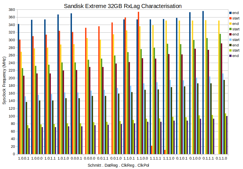
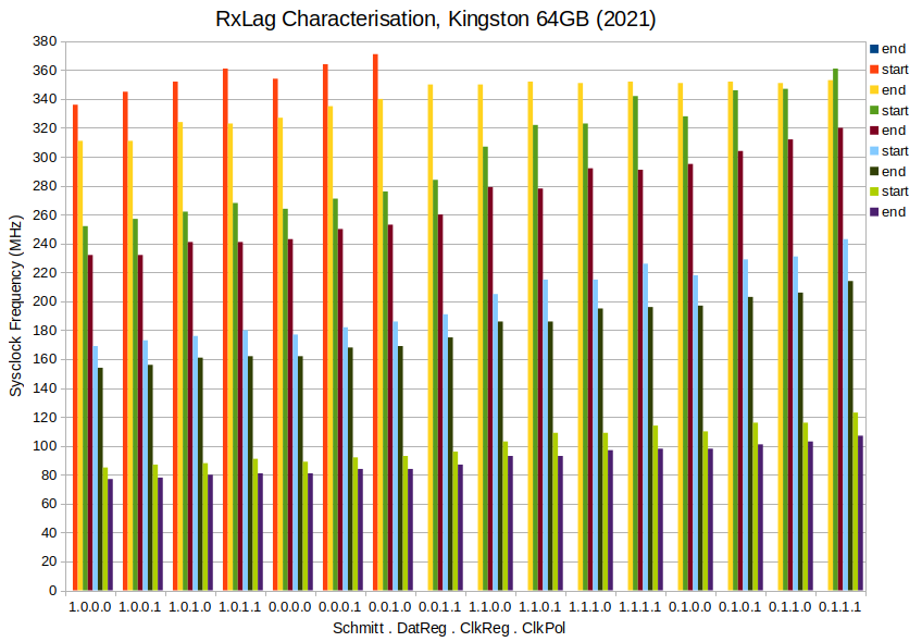
Been refining the routines over the last few days. In the process have added the lag tester covering even more pin configs than ever before. Here's a collation of test results from 16 combinations of four compile switches - In order:
Schmitt Trigger inputs: 1 = enabled, 0 = disabled. Applies to CMD and DAT pins. CLK pin input is always enabled.
Registered CMD and DAT pins: 1 = enabled, 0 = disabled.
Registered CLK pin: 1 = enabled, 0 = disabled.
Clock Polarity: 1 = inverted, 0 = non-inverted. Inverted also sets the SD card to Default-Speed access mode. Non-inverted sets High-Speed access mode.
PS: There is one data point (22 MHz) that I've made up. I placed that there to remind me that that combination (1.1.1.1) failed badly at very high sysclock frequencies. Above 360 MHz, with room temp at 20 oC, all rxlag compensation values produced corrupted read data. And done at sysclock/4 too, so the SD clock wasn't all that high.
@evanh
Am confused as to how to read your chart. What are "start"s and "end"s and what are the different colours for the different combinations of the 4bit binary states?
The four digits of the sixteen groups are the enabled/disabled of that compiled run producing a set of data points. The data points from a run are the ends and starts. The sixteen runs are sorted roughly in order of tallness.
The ends and starts are cryptic, yes. I was going to post an example of the typical data dump from a run before I went to bed but actually forgot why I wanted to, so didn't in the end. It's just the old rxlag behaviour dump ... where an "end" is where a 100% column finishes and a "start" is where a fresh 100% column begins. Here's a chunk of the worst case 1.1.1.1:
I haven't yet worked out how useful this all is. It might help with sysclock/2 read operations if I settle on using that.
Obviously won't use the 1.1.1.1 combination.
I've also learnt that 1.1.1.0 is the next weakest combination. It fades out above 370 MHz at 19 oC room temp.
I did start out with a negative view of registered CMD/DAT pins but after building the graph I've decided otherwise. Those have less starts and ends and the tallest steps. In the dump files it's no so clear because the register stage adds +1 to rxlag values.
EDIT: Here's a newer graph with an extra "end" shown at the tops of some runs. The colours have all shifted as a result.
Here's my current working source code. I'm also using pllset() for setting sysclock - https://obex.parallax.com/obex/pllset/
PS: WARNING! This is setup to do raw block writes to any SD card that's inserted. You'll want to reformat the card afterward.
Ok thanks for explaining it a bit more. The sorting of the 4 bit state is interesting. It shows how you might be able to effectively push up and down the start/end of a band of operating frequencies for a specific delay value. This could be useful to help center a given operating frequency in the middle of the range to help provide some margin either side for any temperature/voltage/process variation of the P2, and the SD card itself may also have some timing variations as well for the same reasons.
Yes, exactly. That's what I'm hoping to glean from it. Or at the very least some peace of mind that I've looked under every rock.
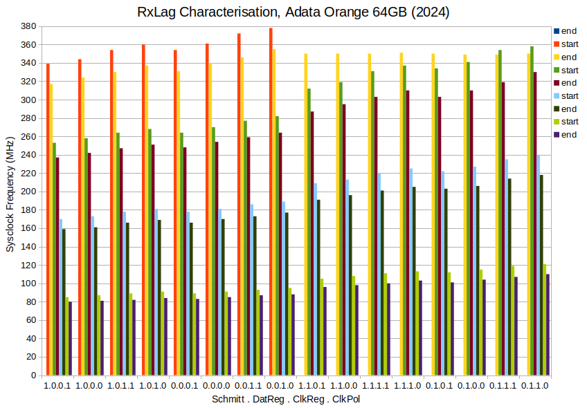
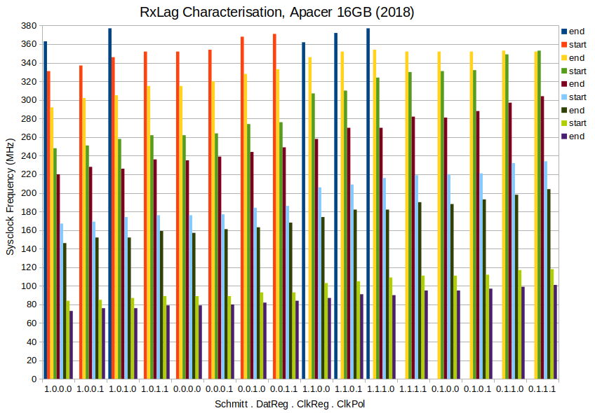
EDIT: But making up another chart, this time for my oldest (2013) Adata 16GB card, has revealed there isn't much consistency in what is the strongest contributors to the slope. Registered CMD/DAT pins is still the strongest factor but after that it is all rearranged. Clock polarity has moved up from 4th to 2nd place.
EDIT2: Three more (Same sort order as the Sandisk). All three had 16 clean runs each, no screwy results at top end:
First attempt was simply to read one block then process the CRC serially before moving on to the second block, and so on. Which worked fine but basically halved the overall data rate from 40+ MB/s to maybe 22 MB/s. So naturally I wanted to find a better way to keep the data flowing ...
I then went to town and built a routine with dual buffer pointers and lots of locals to run a CRC check in parallel with the streamer's reading of the SD card. I have the whole C function loaded to lutRAM, leaving the Fcache space in cogRAM free for my CRC data ...
And after some bug fixes it ran ... but pretty much hadn't budged in speed at all! I was like, What have I missed? It's working functionally really well. There is even error checks that helped lots with the debugging. I'd removed the old CRC code path so it wasn't doubling up on that ... then it dawned on me, the FIFO's writes are a hog on hubRAM accesses! And I'm trying to fast copy from hubRAM into cogRAM a whole 512+8 byte block of data at the same time as the streamer is using the FIFO for writing to hubRAM ...
So I add in an interval check of the fast copy and sure enough it's taking almost the entire active streamer time to also do the fast copy when the streamer is operating the SD card at a clock divider of sysclock/3 and also sysclock/4.
Oh man, you must be hammering the HUB big time. I have a similar thing in my video driver, with the streamer pumping pixels and me block reading the next scan line into LUT RAM and then writing back for pixel doubling and this makes good use of the bandwidth available. In this case it is doing reads and it sounds like you are doing writes (reading off SD). I'm somewhat surprised you are hitting HUB limits though - maybe FIFO writes are less efficient than reads. Perhaps there is some way to stage your block reads in smaller quantities that fit better with the FIFO bursts and don't starve the FIFO out for the streamer. You might gain something that way perhaps, not sure. Haven't done the numbers.
@rogloh said:
... - maybe FIFO writes are less efficient than reads.
Hugely so! That's the big discovery that Tony and I found a couple years back. It was a shock at that time that reads and writes were so different. This is the first time I've hit it in a real use case.
Perhaps there is some way to stage your block reads in smaller quantities that fit better with the FIFO bursts and don't starve the FIFO out for the streamer.
The FIFO staves the Cog, FIFO always gets priority.
@evanh said:
It was a shock at that time that reads and writes were so different.
Basically, rule is, FIFO writes of a byte size, or more, are written at first opportunity. Which can mean each and every rotation of the hub. Each time that this clashes with a cog access to hubRAM the cog then has to wait another full rotation to get in. By which time the FIFO may well want to write that very same slice again. Stalling the cog for consecutive rotations!
So that explains why there is a large drop in congestion between sysclock/4 and sysclock/5. The streamer is reading nibbles from the SD card and writes bytes to the FIFO on every second cycle. Which in turn means when the streamer is cycling at sysclock/4 the FIFO is writing on every hub rotation, but when the streamer is cycling at sysclock/5 the FIFO is starting to write less than every hub rotation.


Comments
I still got some bugs to iron out:
P_INVERT_OUTPUTbug fix.P_INVERT_OUTPUTbug fix.UPDATE: Right, fixed two with one stone: Part of making the High-Speed mode changes function cleanly was to revert the SD clock back to positive polarity. For Default-Speed I'd had
P_INVERT_OUTPUTapplied to the clock pin. ... Well, I'd failed to thoroughly apply the reversion to all the needed parts of the source code. There is a lot places where the clock smartpin is reconfigured. Each one reapplies the inversion or not.Well, I've been running the combinations and am now settling on using P_PULSE for clock gen. Even though it creates a little more bloat when adjusting the clock divider, it has its advantages. I hadn't used P_TRANSITION very much and thought I better actually compare them.
It turns out there is a notable advantage with the start-bit search, of both the command response and data blocks, where P_PULSE can be operated at double the rate of P_TRANSITION. (A little clarification: I've also decided that I want to avoid using input redirection so then no restrictions of where each pin is assigned. This means that the P_PWM_SMPS smartpin mode is off limits for the start-bit search.)
With P_PULSE, the streamer lead-in is computed to a whole SD clock cycle after DIRH, but with P_TRANSITION this is a half-cycle instead. That whole cycle available to the lead-in can be taken advantage of by shifting the streamer's first sample ahead of the first clock pulse gen. Ie: Read in the already present response's T bit, or first data bit, that has been presented by an overclocked start-bit search.
Another advantage of P_PULSE is it can handle sysclock/3. And that is actually a nice divider to use. It has the same rx sampling reliability that sysclock/4 has. Adjusting rxlag to align with the centre slot is hugely better than having to pick from two questionable sample points with sysclock/2.
That said, I guess making use of pin registration like we did with HyperRAM helps alleviate this at sysclock/2. It's something still to be investigated. It may have a negative impact on the above start-bit searching speed.
I've learnt that the Sandisk cards will go faster than 50 MB/s. They also have the worst latencies generally.
None of the others will though. Those others just add extra latency to make any SD clock rate above about 110 MHz ineffective.
I'm thinking of settling on sysclock/2 for sysclocks up to 200 MHz. Above that use sysclock/3. Keeps the decision tree small and will still give ridiculously high performance.
So with your start bit search approach, how much time is wasted now after after the start bit actually occurs? IMO I don't think it really has to be 100% optimal for command transfers, given the larger percentage of time allotted to the data transfer itself vs overall time of entire transfer and its outer CMD transaction. For data it does need to be fast in order to respond in time.
As to sysclk/2 vs sysclk/3 I know I was still able to get sysclk/2 transfer rates working at high P2 speeds though perhaps I just was lucky with my choice of card - it should be documented somewhere earlier in this thread... here it was:
https://forums.parallax.com/discussion/comment/1545820/#Comment_1545820
Each block also has the same search. It definitely impacts throughput. I report both bulk data and command/response performances now, in a bulk repeating manner, to gauge which combinations of methods fit together.
It's definitely card dependant. My oldest card, the Adata, struggles above 100 MHz SD clock.
Command/response runs for one card (Kingston) at one clock rate (40 MHz sysclock, 20 MHz SD clock):
EDIT: In hindsight, some those results are a little dubious. Two of those options, the "block" related ones, shouldn't impact the command/response performance. Yet there is differences. EDIT2: I suppose it could be put down to CALL/RET execution speed with different hubRAM alignments for different compile options.
Response handlers #2 and #3 are similar, #4 is clearly slower and that's because it uses the slowest one clock at a time for its search method. However response handler #3 uses P_PWM_SMPS so its search is not impacted by the clock gen smartpin mode. It is therefore also disqualified for using pin redirection. Response handlers #1 is also disqualified because it doesn't use the streamer so can't calibrate rxlag.
Hmm, thinking about the posted times. They are very rounded in lots of 0.1 ms. Uh-oh, I'm not verifying any validity of the responses in that test ...
EDIT: Shrug Seems fine. No timeouts and CRCs all check out.
Huh, of course, convention has made the data block's nibble order as big-endian. There's nothing stopping FAT filesystems using least nibble as first in the data block bytes, but it just isn't.
Typical of the PC world. They often mix big-endian and little-endian because Intel has always used big-endian number format for documentation - which is not all that surprising given we are only taught big-endian numbers at school. So this all spills over into implementations, creating those confusing mixes.
LOL, endianness matters yet again. Having grown up with Z80 and x86 LE stuff I remember freaking out a little when I was first exposed to a Motorola PPC405 buses at work and reading the docs seeing them label registers with bit 0 on the left side of a 32 bit binary value in the MS bit position increasing to 31 on the right side as the LS bit position. I knew it used big-endian inherently and can even switch to a little-endian mode too but at the time I just couldn't get my head around why on earth it was written like that. Also their A0 was the most significant address bit and A31 was the least. Bizarro.
See here for details.
http://www.icbase.com/pdf/IBM/IBM02400107.pdf
IBM didn't really help there. They made it work for LE, that's how Intel should have done their LE. It was a bad way to document BE though. Bit numbering not following significance screwed everyone over.
I guess, to be fair, it did allow IBM to use one diagram to represent both. It was up to the reader of the document to fill in which significance the bits were. I don't think there has ever been a LE PPC processor, so still somewhat academic.
I've used your code but gone with RFLONG and feeding a 32-bit immediate mode streamer op once per loop:
This is sufficient for uninterrupted real-time CRC computing at sysclock/4 - Which I'm happy enough with. It's just a lot easier not using a large cog buffer in the C executing cog.
To transmit the CRCs as 4-bit parallel at the block end, I found a tidy solution with:
rolbyte pa, crc3, #0 rolbyte pa, crc2, #0 rolbyte pa, crc1, #0 rolbyte pa, crc0, #0 mergeb pa xzero mcrc, pa rolbyte pa, crc3, #1 rolbyte pa, crc2, #1 rolbyte pa, crc1, #1 rolbyte pa, crc0, #1 mergeb pa xzero mcrc, pa ...mdatandmcrcare:One thing I haven't yet tried to solve is pin assignment. As you can see above, my test code is relying on compile-time constants, but that's not an option in the finished driver. It'll be painful if I'm inline patching all the streamer modes. It was a more humane process when it was just smartpins or bit-bashed.
I'd like to do all the patching during card init/mount only, but I've not figured out how as yet.
Makes sense this way if you want to save on the LUT space, yeah. I may have coded it that way so it could coexist with some possible parallel reads from HUB via streamer but it's been a while so I can't recall why off hand. Still, it would be nice to be able to support sysclk/2 operation at some point if the underlying HW is capable of that.
Good, seems tight.
Instead of patching code you could probably assign some variable with the pin number and then have the executed mount code at runtime use that variable to generate the correct streamer mode data and other "constants" to be used. This is probably a lot simpler than trying to patch the executable code, but may likely involve developing more actual code. If only done once at init time it's not going slow anything down significantly.
It gets very bulky building the mode words for each and every use on the fly. Applying
rxlagis easier since it's literally only a single add at each case and only applies to some routines. Pin assignments are multiple cases for every routine. Could be as much as ten variables to build up within one routine.At the very least I'd want do a SETQ + RDLONG fast copy to registers from prebuilt structures. I'm fuzzy as to whether this could be done officially in Flexspin without future breakage. Hence I avoided the fast copy to lutRAM earlier.
Actually, I have done this once already and got away with it. It was plain linear data buffer copied into a series of two local variables on the assumption that each local, in source order, would be consecutive registers in the cog. It's actually in Flexspin's existing SPI SD card driver. One occurrence at the head of the byte transmit routine. It reduced two initial RDLONG instructions to one. Pretty minor optimisation but it has proved reliable, afaik.
First basic CMD25 write tests are netting me up to 30 MB/s but is highly card dependant.
EDIT2: Ah, there is one still slow - seems limited to write speed of 10 MB/s. It's an older 16 GB SD card, Apacer brand.
EDIT3: Make that two slow cards. I thought it was better but my oldest 16 GB Adata isn't doing so great either. It's hovering in the 11 to 14 MB/s range.
EDIT4: Actually, each card can vary quite a lot from run to run. So can't really count on consistent write performance at this stage. Now removed first speculation comments because of this.
Well, I think the oddity I had with the Kingston SD card has gone away in the interim. I no longer am getting the timeout when using CMD12 cancelling just after CMD18's response, before first block is read.
I've done a bunch of bug fixes to many of my routines recently, so I guess it had been my fault all along for not following the spec properly.
So now I no longer have any solid reason to use High-Speed over Default-Speed access mode. Which is good because running the rx lag tests indicates that signalling is marginally better in Default-Speed access mode. I suspect this isn't due to changes in a cards behaviour, but rather likely related to the clock inversion that goes with Default-Speed.
In Default-Speed access mode the SD card outputs data to the pins on falling edge of the clock. To make this most responsive for the Prop2 driver it's best to have the leading clock edge be a falling one. And that means idle high, inverted. For some reason this inverted arrangement gives slightly wider margins at the sharp end of 180 MHz SD clock.
EDIT: Hmm, it actually looks like I've had that one fixed for a while now. I've got a backup from 27 June, five days after, where I can't reproduce that timeout behaviour any longer.
Been refining the routines over the last few days. In the process have added the lag tester covering even more pin configs than ever before. Here's a collation of test results from 16 combinations of four compile switches - In order:
PS: There is one data point (22 MHz) that I've made up. I placed that there to remind me that that combination (1.1.1.1) failed badly at very high sysclock frequencies. Above 360 MHz, with room temp at 20 oC, all rxlag compensation values produced corrupted read data. And done at sysclock/4 too, so the SD clock wasn't all that high.
PPS: The Sandisk's CID register decode:
ManID=03 OEMID=SD Name=SE32G
Ver=8.0 Serial=6018369B Date=2017-12
EDIT: Added the 374 MHz data point to 1.1.0.0
@evanh
Am confused as to how to read your chart. What are "start"s and "end"s and what are the different colours for the different combinations of the 4bit binary states?
The four digits of the sixteen groups are the enabled/disabled of that compiled run producing a set of data points. The data points from a run are the ends and starts. The sixteen runs are sorted roughly in order of tallness.
The ends and starts are cryptic, yes. I was going to post an example of the typical data dump from a run before I went to bed but actually forgot why I wanted to, so didn't in the end. It's just the old rxlag behaviour dump ... where an "end" is where a 100% column finishes and a "start" is where a fresh 100% column begins. Here's a chunk of the worst case 1.1.1.1:
I haven't yet worked out how useful this all is. It might help with sysclock/2 read operations if I settle on using that.
Obviously won't use the 1.1.1.1 combination.
I've also learnt that 1.1.1.0 is the next weakest combination. It fades out above 370 MHz at 19 oC room temp.
I did start out with a negative view of registered CMD/DAT pins but after building the graph I've decided otherwise. Those have less starts and ends and the tallest steps. In the dump files it's no so clear because the register stage adds +1 to rxlag values.
EDIT: Here's a newer graph with an extra "end" shown at the tops of some runs. The colours have all shifted as a result.
EDIT2: Spreadsheet attached
Here's my current working source code. I'm also using pllset() for setting sysclock - https://obex.parallax.com/obex/pllset/
PS: WARNING! This is setup to do raw block writes to any SD card that's inserted. You'll want to reformat the card afterward.
Ok thanks for explaining it a bit more. The sorting of the 4 bit state is interesting. It shows how you might be able to effectively push up and down the start/end of a band of operating frequencies for a specific delay value. This could be useful to help center a given operating frequency in the middle of the range to help provide some margin either side for any temperature/voltage/process variation of the P2, and the SD card itself may also have some timing variations as well for the same reasons.
Yes, exactly. That's what I'm hoping to glean from it. Or at the very least some peace of mind that I've looked under every rock.
EDIT: But making up another chart, this time for my oldest (2013) Adata 16GB card, has revealed there isn't much consistency in what is the strongest contributors to the slope. Registered CMD/DAT pins is still the strongest factor but after that it is all rearranged. Clock polarity has moved up from 4th to 2nd place.
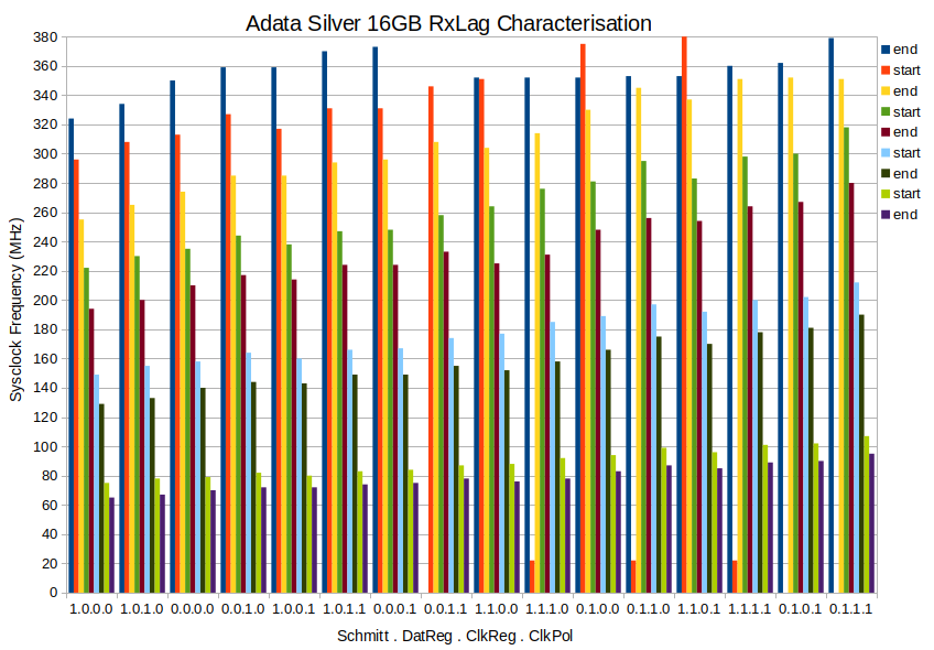
EDIT2: Three more (Same sort order as the Sandisk). All three had 16 clean runs each, no screwy results at top end:
Following on from the FBLOCK fiasco - https://forums.parallax.com/discussion/175955/fblock-feature-possibly-flawed/p1
I started pondering the actual data block CRC processing method rather than the most convenient place of store.
First attempt was simply to read one block then process the CRC serially before moving on to the second block, and so on. Which worked fine but basically halved the overall data rate from 40+ MB/s to maybe 22 MB/s. So naturally I wanted to find a better way to keep the data flowing ...
I then went to town and built a routine with dual buffer pointers and lots of locals to run a CRC check in parallel with the streamer's reading of the SD card. I have the whole C function loaded to lutRAM, leaving the Fcache space in cogRAM free for my CRC data ...
// check CRC of prior read SD block
        cmp priorbuf, #0   wz
    if_a    setq    #(512+8)/4-1    // one SD block + CRC
    if_a    rdlong  0, priorbuf    // fast copy to cogRAM
    if_a    mov pb, #0
    if_a    rep @.rend, #(512+8)/4    // one SD block + CRC
    if_a    alti    pb, #0b111    // next S-field substitution, then increment PB
    if_a    mov pa, 0-0
    if_a    movbyts pa, #0b00_01_10_11
    if_a    splitb  pa
    if_a    setq    pa
    if_a    crcnib  crc3, poly
    if_a    crcnib  crc3, poly
    if_a    crcnib  crc2, poly
    if_a    crcnib  crc2, poly
    if_a    crcnib  crc1, poly
    if_a    crcnib  crc1, poly
    if_a    crcnib  crc0, poly
    if_a    crcnib  crc0, poly
.rend
And after some bug fixes it ran ... but pretty much hadn't budged in speed at all! I was like, What have I missed? It's working functionally really well. There is even error checks that helped lots with the debugging. I'd removed the old CRC code path so it wasn't doubling up on that ... then it dawned on me, the FIFO's writes are a hog on hubRAM accesses! And I'm trying to fast copy from hubRAM into cogRAM a whole 512+8 byte block of data at the same time as the streamer is using the FIFO for writing to hubRAM ...
So I add in an interval check of the fast copy and sure enough it's taking almost the entire active streamer time to also do the fast copy when the streamer is operating the SD card at a clock divider of sysclock/3 and also sysclock/4.
The 143 will be an uninterrupted clean fast copy.
So this effect basically wreaks this concurrent fast copy approach.
Which means options are:
Oh man, you must be hammering the HUB big time. I have a similar thing in my video driver, with the streamer pumping pixels and me block reading the next scan line into LUT RAM and then writing back for pixel doubling and this makes good use of the bandwidth available. In this case it is doing reads and it sounds like you are doing writes (reading off SD). I'm somewhat surprised you are hitting HUB limits though - maybe FIFO writes are less efficient than reads. Perhaps there is some way to stage your block reads in smaller quantities that fit better with the FIFO bursts and don't starve the FIFO out for the streamer. You might gain something that way perhaps, not sure. Haven't done the numbers.
Hugely so! That's the big discovery that Tony and I found a couple years back. It was a shock at that time that reads and writes were so different. This is the first time I've hit it in a real use case.
The FIFO staves the Cog, FIFO always gets priority.
Basically, rule is, FIFO writes of a byte size, or more, are written at first opportunity. Which can mean each and every rotation of the hub. Each time that this clashes with a cog access to hubRAM the cog then has to wait another full rotation to get in. By which time the FIFO may well want to write that very same slice again. Stalling the cog for consecutive rotations!
So that explains why there is a large drop in congestion between sysclock/4 and sysclock/5. The streamer is reading nibbles from the SD card and writes bytes to the FIFO on every second cycle. Which in turn means when the streamer is cycling at sysclock/4 the FIFO is writing on every hub rotation, but when the streamer is cycling at sysclock/5 the FIFO is starting to write less than every hub rotation.