Cool @evanh. Yeah the variable length one will be useful for checking responses too.
I think for computing 4 lane CRCs in the example code I posted earlier we may need to first split the nibbles so they convert into the correct lane format for doing CRCs. Probably needs some suitable combination of movbyts/splitb/mergeb etc, but I think it will be doable without many extra instructions.
I think it's gonna be something like 3330 cycles or so for the 4xCRC stuff (up from 2800). We need the movbyts and splitb which also necessitates keeping the setq
    setq2 #128-1 ' 512 bytes
    rdlong 0, databuf ' read from HUB to LUT
    rep #12, #128 ' repeat 128 times (@25 clocks per iteration = 3200 cycles)
    rdlut data, ptra++ ' get data
    movbyts data, #%%0123
    splitb data
    setq data
    crcnib crc3, poly
    crcnib crc3, poly
    crcnib crc2, poly
    crcnib crc2, poly
    crcnib crc1, poly
    crcnib crc1, poly
    crcnib crc0, poly
    crcnib crc0, poly
Also I wonder if we can stream from the DAT pins and make them input smartpins at the same time? If so we might be able to have them detect the falling edge or start bit or something while the streamer is going/preparing itself...?
I also think the LED smartpin could be used for RX of the CMD line. Nice to have P2 pins doing double duty where possible.
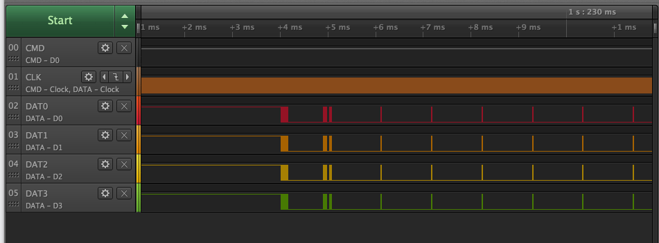
For a laugh I boosted the clock to 1MHz and did the read multiple operation and see it takes only 15us between the sectors being sent (this is a SD Ultra 16MB card class 10). I should boost it to 25-50MHz to see if this pattern continues or slows down but I'd need the scope instead as the Logic Analyzer can only sample to 16MHz. If this is to be expected, then at 50MHz you could stream sectors at 14MB/s or so with this card (until it hits a pause for any reason).
Edit: It might not be some fixed time but a certain number of clocks between sectors too, so performance may increase with clock speed. For the 14MB/s I was assuming a fixed 15us gap plus 20us transfer time or so for the sector at 50MHz (~1040 bits).
Each one of the pulses in the DAT lines is the idle time between sectors.
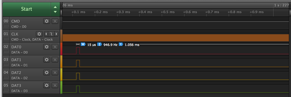
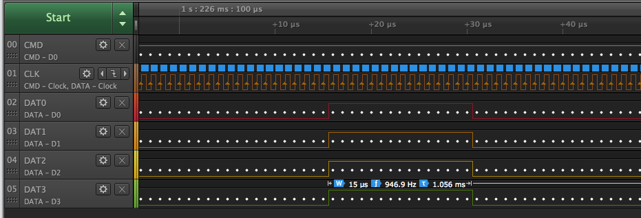
Zooming in you can see the time between sectors.
It looks like the 15 clock per sector gap is still there with 25MHz operation when I captured it on my scope. So it scales with clock frequency. This means that it can achieve close to 12.5MB/s with multiple sector transfers while it is bursting like this.
I still need to try 50MHz and actually try to get the data into the P2 off the nibble bus with the streamer.
Also I found that the sectors always seem to come in after the read response on the CMD pin on my Sandisk card. If this is true in general, it may mean that it is not necessary to clock CMD and DAT pins at the same time. If you need to cancel a multiple read command while it is streaming you can always stop reading the DAT signals before you cancel the read, and then utilize the COG's time to read back the CMD response for that operation (so nothing should be missed there). And for writes, you control the DAT and can wait for the CMD reply or end of busy before issuing the next CMD, or sector write etc. The CRC reply from the card happens right after the end of the DAT transfer.
Having the ability to stop the clock really helps here.
Good, and makes more sense since 50 MHz is meant to be up for peak of 25 MB/s data rate.
EDIT: Although, once the overheads are subtracted, the data rate will measure nerf'd ... for every block, 128 clocks for data, 16 for CRC, 2 for start-stop, and 15 for inter-block gap:
128+16+2+15=161
128 / 161 = 0.795
25 * 0.795 = 19.875 MB/s (decimal scale)
19.875 * 0.9537 = 18.95 MB/s (binary scale)
Interesting observation... if I switch a card into 50MHz max speed mode, the CMD response seems to shift by 1/2 a bit. i.e. data now changes on the rising clock edge instead of the falling edge, as seen for the standard 25MHz mode. I was seeing CRC errors returned in this mode, and this explains why and the bits were off by 1 in my rx shift register.
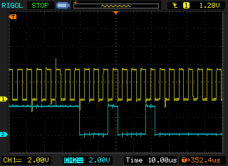
At 25MHz max speed
Blue = CMD response, Yellow = CLK
At 50MHz max speed (note: CMD is not being clocked at this speed)
@rogloh said:
Interesting observation... if I switch a card into 50MHz max speed mode, the CMD response seems to shift by 1/2 a bit. i.e. data now changes on the rising clock edge instead of the falling edge, as seen for the standard 25MHz mode.
Using CMD 6 for High Speed mode, right? Yes, it depends on the brand/model of SD card. Some change edge like that, some don't. I suspect there isn't any advantage changing to High Speed mode. You can clock faster than 25 MHz in Default Speed mode. The real speed-ups are in the low voltage UHS modes and enhanced modes beyond.
@evanh said:
Using CMD 6 for High Speed mode, right?
Yeah.
Yes, it depends on the brand/model of SD card. Some change edge like that, some don't. I suspect there isn't any advantage changing to High Speed mode. You can clock faster than 25 MHz in Default Speed mode. The real speed-ups are in the low voltage UHS modes and enhanced modes beyond.
Wow, you seem to be right. Just tried in standard mode at 100MHz clock and it still read the sector with a good CRC match!
This is bursting at 50MB/s off the card. Nice! Need to try to stream some video stuff now with a multiple read.
Update: Can't quite believe this: P2@350MHz is still reading the SD sector at 175MHz which is ~ 83.5MB/s. Must have fluked those series resistors and layout. Had to tweak the streamer/clock startup delay of course, as the frequency increased, just like the memory stuff does. But it worked. Totally bizarre.
Yes it is Tubular. Until I verified the P2 clock via LED flashing at 1Hz with waitx ##350000000, I assumed I'd not setup the clock frequency correctly and it was still running slower.
@evanh I think I'd fitted 47k pullup resnets to my version, instead of the 22k in the original schematic. And you board had them swapped to 10k IIRC in case it makes any difference in performance.
I was also wondering about the 1.8V UHS-I operation mode of an SD card with DDR. I think it might be possible to at least write data at this voltage if the bitDAC output levels are used to drop down to 1.8V logic high (I know it can work with the streamer like we had with TMDS/DVI). For reads it might be harder to detect a correct logic high, although it may not matter if it can still be read fast at 3.3V instead. How fast does that pin comparator mode work at again? It was somewhat slow wasn't it?
My memory is that the comparator could respond to something like 40 MHz, but I wouldn't be surprised if there was considerable phase shift happening.
I think during that testing we were using the bitdac to send discrete voltage levels, and the 75 or 123 ohm impedance may have been limiting things a bit too
@evanh said:
Roger,
Are you using CMD 3 and CMD 7? Or is card select unimportant when only one SD card?
Both. Pretty sure you'd need to select it. A card won't know the difference when there is one or more than one in a system.
@Tubular said:
My memory is that the comparator could respond to something like 40 MHz, but I wouldn't be surprised if there was considerable phase shift happening.
@evanh said:
Correct. I've forgotten exactly but it is quite a lot slower than plain logic/Schmitt.
Yeah I was able to perform read transfers quite fast in a simple test some time back even at 3.3V levels. Haven't tested the writes. The final answer will probably be something less than 83.5MB/s once other delays and overheads are factored in and the speed of the card. Slower cards may introduce some additional delays between sectors. The card I used was a Sandisk Ultra (class 10 SDHC "UHS-I" Roman numeral rated) and seemed to be able to almost output back to back sectors with only about 15 clocks between them (but it might perform worse if the file is fragmented in the file system). Haven't got back to try out 1.8V operation or writes. Probably no urgent need for doing 1.8V if the cards are already this fast at 3.3V and the P2 is limited to 35MT/s in comparator mode unless you want to try to strictly meet the voltage spec for fast writes. Also doesn't class 10 mean a card can only sustain 10MB/s anyway.
@evanh said:
Class 10 is a minimum of what a card must do, not what a card can do.
True, and it would not necessarily limit to 10MB/s but I'd expect it may not be able to guarantee higher either under all conditions. So you can probably only assume 10MB/s writes for any given class 10 card in some sustained writing environment, even though in practice you'll see something higher than that. After the summer break I might try to get back to this stuff and test writes...


Comments
Cool @evanh. Yeah the variable length one will be useful for checking responses too.
I think for computing 4 lane CRCs in the example code I posted earlier we may need to first split the nibbles so they convert into the correct lane format for doing CRCs. Probably needs some suitable combination of movbyts/splitb/mergeb etc, but I think it will be doable without many extra instructions.
It sucks that 4-bit mode isn't a single CRC per block. Especially given 1-bit mode is exactly that.
I think it's gonna be something like 3330 cycles or so for the 4xCRC stuff (up from 2800). We need the movbyts and splitb which also necessitates keeping the setq
setq2 #128-1 ' 512 bytes rdlong 0, databuf ' read from HUB to LUT rep #12, #128 ' repeat 128 times (@25 clocks per iteration = 3200 cycles) rdlut data, ptra++ ' get data movbyts data, #%%0123 splitb data setq data crcnib crc3, poly crcnib crc3, poly crcnib crc2, poly crcnib crc2, poly crcnib crc1, poly crcnib crc1, poly crcnib crc0, poly crcnib crc0, polyAlso I wonder if we can stream from the DAT pins and make them input smartpins at the same time? If so we might be able to have them detect the falling edge or start bit or something while the streamer is going/preparing itself...?
I also think the LED smartpin could be used for RX of the CMD line. Nice to have P2 pins doing double duty where possible.
This is sector 0 being read. I see 0x55AA nibbles at the end of the sector before the 16 bits of CRC so this should be the MBR data.
This is the start of the same sector after a start bit. 4096/4+17 total bits. Clocking at 200kHz for now.
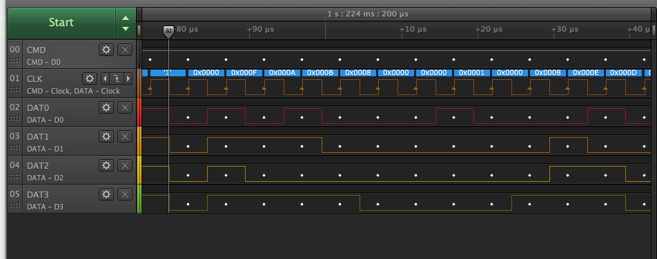
Is that two commands and a response before the data?
I think it was probably showing two prior commands and their long responses followed later by the actual read.
For a laugh I boosted the clock to 1MHz and did the read multiple operation and see it takes only 15us between the sectors being sent (this is a SD Ultra 16MB card class 10). I should boost it to 25-50MHz to see if this pattern continues or slows down but I'd need the scope instead as the Logic Analyzer can only sample to 16MHz. If this is to be expected, then at 50MHz you could stream sectors at 14MB/s or so with this card (until it hits a pause for any reason).
Edit: It might not be some fixed time but a certain number of clocks between sectors too, so performance may increase with clock speed. For the 14MB/s I was assuming a fixed 15us gap plus 20us transfer time or so for the sector at 50MHz (~1040 bits).
Each one of the pulses in the DAT lines is the idle time between sectors.
Zooming in you can see the time between sectors.
It looks like the 15 clock per sector gap is still there with 25MHz operation when I captured it on my scope. So it scales with clock frequency. This means that it can achieve close to 12.5MB/s with multiple sector transfers while it is bursting like this.
I still need to try 50MHz and actually try to get the data into the P2 off the nibble bus with the streamer.
Also I found that the sectors always seem to come in after the read response on the CMD pin on my Sandisk card. If this is true in general, it may mean that it is not necessary to clock CMD and DAT pins at the same time. If you need to cancel a multiple read command while it is streaming you can always stop reading the DAT signals before you cancel the read, and then utilize the COG's time to read back the CMD response for that operation (so nothing should be missed there). And for writes, you control the DAT and can wait for the CMD reply or end of busy before issuing the next CMD, or sector write etc. The CRC reply from the card happens right after the end of the DAT transfer.
Having the ability to stop the clock really helps here.
Good, and makes more sense since 50 MHz is meant to be up for peak of 25 MB/s data rate.
EDIT: Although, once the overheads are subtracted, the data rate will measure nerf'd ... for every block, 128 clocks for data, 16 for CRC, 2 for start-stop, and 15 for inter-block gap:
128+16+2+15=161
128 / 161 = 0.795
25 * 0.795 = 19.875 MB/s (decimal scale)
19.875 * 0.9537 = 18.95 MB/s (binary scale)
I think the stop bit might effectively be the first bit of the 15. Also it's 1024 clocks for a sector of 512B.
Doh! I used 512 bits didn't I ....
1024+16+2+14=1056
1024 / 1056 = 0.9697
25 * 0.9697 = 24.24 MB/s (decimal scale)
24.24 * 0.9537 = 23.12 MB/s (binary scale)
Got it working at 25MHz clock (for now). Streamer being used in inline PASM code. CRCs match. This is my card's boot sector.
Ugh, I'm not focussed at all.
cool
Mike
Interesting observation... if I switch a card into 50MHz max speed mode, the CMD response seems to shift by 1/2 a bit. i.e. data now changes on the rising clock edge instead of the falling edge, as seen for the standard 25MHz mode. I was seeing CRC errors returned in this mode, and this explains why and the bits were off by 1 in my rx shift register.
At 25MHz max speed
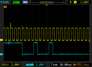
Blue = CMD response, Yellow = CLK
At 50MHz max speed (note: CMD is not being clocked at this speed)
Using CMD 6 for High Speed mode, right? Yes, it depends on the brand/model of SD card. Some change edge like that, some don't. I suspect there isn't any advantage changing to High Speed mode. You can clock faster than 25 MHz in Default Speed mode. The real speed-ups are in the low voltage UHS modes and enhanced modes beyond.
Yeah.
Wow, you seem to be right. Just tried in standard mode at 100MHz clock and it still read the sector with a good CRC match!
This is bursting at 50MB/s off the card. Nice! Need to try to stream some video stuff now with a multiple read.
Update: Can't quite believe this: P2@350MHz is still reading the SD sector at 175MHz which is ~ 83.5MB/s. Must have fluked those series resistors and layout. Had to tweak the streamer/clock startup delay of course, as the frequency increased, just like the memory stuff does. But it worked. Totally bizarre.
Wow thats impressive
Wow, yeah, way more than I thought would be possible. I had held my breath on those resistors too. Good call.
Yes it is Tubular. Until I verified the P2 clock via LED flashing at 1Hz with waitx ##350000000, I assumed I'd not setup the clock frequency correctly and it was still running slower.
@evanh I think I'd fitted 47k pullup resnets to my version, instead of the 22k in the original schematic. And you board had them swapped to 10k IIRC in case it makes any difference in performance.
I was also wondering about the 1.8V UHS-I operation mode of an SD card with DDR. I think it might be possible to at least write data at this voltage if the bitDAC output levels are used to drop down to 1.8V logic high (I know it can work with the streamer like we had with TMDS/DVI). For reads it might be harder to detect a correct logic high, although it may not matter if it can still be read fast at 3.3V instead. How fast does that pin comparator mode work at again? It was somewhat slow wasn't it?
Roger,
Are you using CMD 3 and CMD 7? Or is card select unimportant when only one SD card?
My memory is that the comparator could respond to something like 40 MHz, but I wouldn't be surprised if there was considerable phase shift happening.
I think during that testing we were using the bitdac to send discrete voltage levels, and the 75 or 123 ohm impedance may have been limiting things a bit too
Correct. I've forgotten exactly but it is quite a lot slower than plain logic/Schmitt.
EDIT: Upper limit is 35 MT/s - https://forums.parallax.com/discussion/comment/1543775/#Comment_1543775
Both. Pretty sure you'd need to select it. A card won't know the difference when there is one or more than one in a system.
Thanks.
Yeah 40MHz doesn't buy us too much there then.
So the best we could hope for writing is around 20MB/s without level shifters?
Yeah I was able to perform read transfers quite fast in a simple test some time back even at 3.3V levels. Haven't tested the writes. The final answer will probably be something less than 83.5MB/s once other delays and overheads are factored in and the speed of the card. Slower cards may introduce some additional delays between sectors. The card I used was a Sandisk Ultra (class 10 SDHC "UHS-I" Roman numeral rated) and seemed to be able to almost output back to back sectors with only about 15 clocks between them (but it might perform worse if the file is fragmented in the file system). Haven't got back to try out 1.8V operation or writes. Probably no urgent need for doing 1.8V if the cards are already this fast at 3.3V and the P2 is limited to 35MT/s in comparator mode unless you want to try to strictly meet the voltage spec for fast writes. Also doesn't class 10 mean a card can only sustain 10MB/s anyway.
Class 10 is a minimum of what a card must do, not what a card can do.
True, and it would not necessarily limit to 10MB/s but I'd expect it may not be able to guarantee higher either under all conditions. So you can probably only assume 10MB/s writes for any given class 10 card in some sustained writing environment, even though in practice you'll see something higher than that. After the summer break I might try to get back to this stuff and test writes...