

"Blitzen 24" E1.31 Pixel Light Controller Updates thread.
 ke4pjw
Posts: 1,334
ke4pjw
Posts: 1,334
Creating a new thread dedicated to progress on my pixel light controller.
Older information can be found here and here
Source code and up to the moment project status can be seen here.
The past few weeks I have completed the E1.31 configuration via web browser: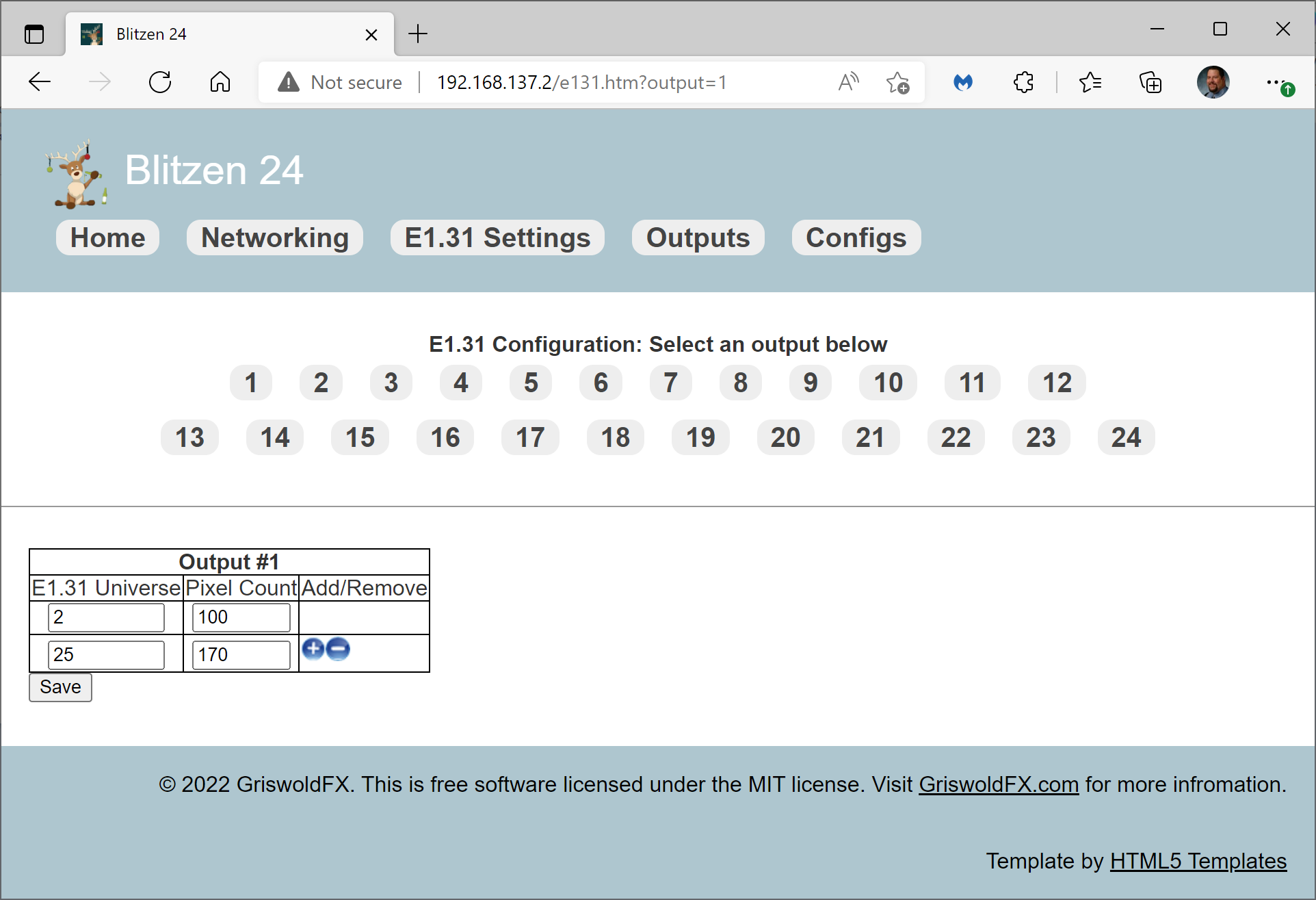
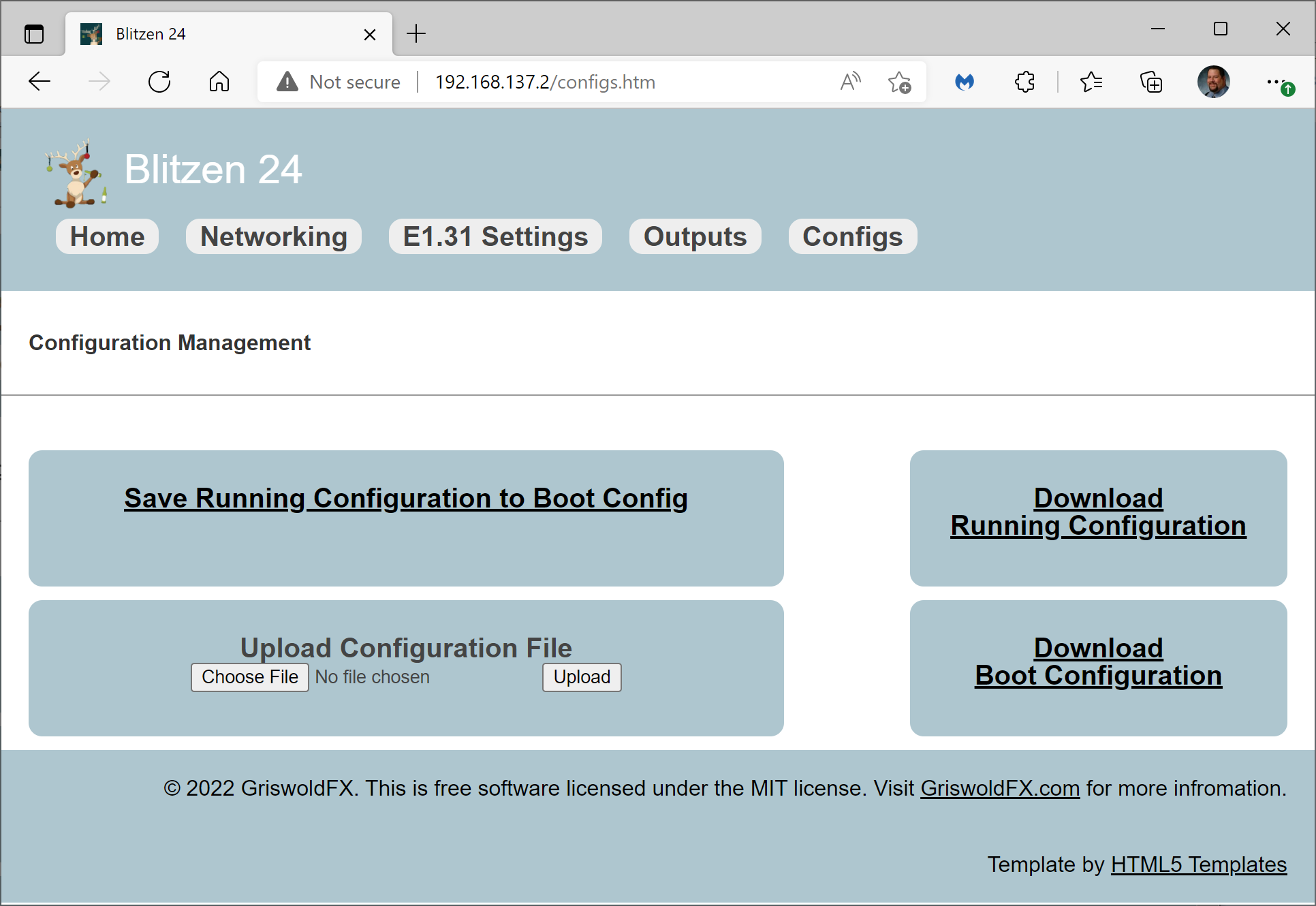
Additionally, I have adopted a "Running Config" and "Boot Config" type of paradigm for the controller, like you would see with Cisco IOS. This allows you to tweek the settings and can return to what you started with by power cycling. You can also download and upload the configuration via web browser. Configuration is stored on the SD card.
The last core functionality missing is configuring the outputs for 400khz and 800khz, as well as pixel color order.
At this time, I do not think I want to support RGBW pixels.
If anyone is interested in contributing to the project, please reach out. I have a spare W6100.
--Terry
Comments
this looks very good.
Mike
Thanks @msrobots !
Here is a video of updating the config on the fly.
Cool project
I am close to an initial release. There is some technical debt that needs to be eliminated first.
Output configuration page is working.
I have 9 W6100L chips arriving tomorrow. I need to complete the board layout. I am going to build the first few to use P2Edge cards, because it is easy") It will require Edge cards with an SD slot. The board will have level corrected (5v), buffered outputs with matching resistors to drive the pixels.
It will require Edge cards with an SD slot. The board will have level corrected (5v), buffered outputs with matching resistors to drive the pixels.
I am currently adding quad DMX outputs. The last feature is to drive a small SSD1331 display to show the IP address. I will then call it a 1.0 Release.
Strech goal will be to have it be able to upgrade itself via the Internet. I will have to implement DNS, but that shouldn't be too hard.
Unfortunately for the project, boat season has arrived. That means I will have less time to dedicate to the project, however I intend to actually schedule time for the project each week.
If anyone is interested in contributing, let me know. Even if to be a tester/user. I will probably have half a dozen boards available by mid-July.
As for using P2 Edge cards in your project, while you're still at the design/layout phase, perhaps I can add a mild contribution...
There are two forcefully NC pins (1 and 2) at every Edge card that I believe wheren't used in any of the currently available breakout or breadboard versions, intended to be unused, mainly due the fact that, in case of reverse-installing the Edge at the connector (180º), the card Edge pads that would get connected to them are the VIN_Edge ones.
Also, in case of reverse-installing the P2 Edge, connector pins P35, P36, and P37 will get shorted due to the fact that the respective pads are GND at the Edge card.
The above didn't mean the Edge card can be harmed in any way by inserting it reversed, at the connector, but I don't know anything about the way you've planed to use P2_IO35 thru P2_IO37 at your board (nor even if they were used, at all).
So, perhaps there's at least one way of leveraging the fact that, in case of a reverse-installed Edge card, those two "now-shorted-pins" can be used to preclude your board to "misbehave" in any way it could get harmed, due to that "now-twisted-Edge-condition".
Hope it helps
Henrique
Thanks for the info Henrique!
It is mid-July and I haven't finished board layout. I need to get that complete. I added the OLED code, so that you will know the IP address of the Blitzen upon boot. It also displays the MAC address, and has icons for E1.31 status and Ethernet status.
The E1.31 icon is red if no E1.31 packets are received in the past second, green if it has, and yellow if there were any discards. Discards are E1.31 packets where the destination universe is not known to the Blitzen and is discarded.
The Ethernet icon is red if disconnected, yellow if link is down, and green if both cable is plugged in and link is up.
Counters were added to the homepage that count received E1.31 packets and discards.
Just a quick update. I did a board layout using traditional through hole components and the P2 Edge. Looks like everything from a hardware perspective worked out first try, though I am going to move some components around to give some wiggle room before doing a small production run.
The board has 24 pixel outputs that can be supported by 4 separate power supplies. Pixel power supply can be independent from powering the logic on the board. Logic for the board can be driven by 5v or 12v supplies. (Most pixels are 5v or 12V) Each pixel output has its own fuse. Pixel outputs are driven by 5V line drivers with a 100ohm resistor on the output.
Hardware To Do:
Validate the quad DMX output hardware works as expected. This feature is incomplete in the software.
Validate HDMI output on the 12 pin connector actually works.
Software to do:
Complete implementation of Quad DMX output.
Fix the pixel "glitching" that is visible in the video. Most likely a timing issue related to changing the matching resistor value.
Complete implementation of pixel timing selection.
Fix maximum pixels per cog based on maximum pixels per pin group.
PS: Updated a couple of major bugs in the software last night. https://griswoldfx.visualstudio.com/Blitzen 24
Cool.
So, after verifying the hardware, when I went to add the quad-dmx object, I realized I'm

1 - Main/Boot/Webserver Cog
2 - SD Card Cog
3 - HDMI Cog
4 - Watchdog/Stats Cog
5 - E1.31 Cog Time sensitive operation
6 - Pixel Cog Time sensitive operation
7 - Pixel Cog Time sensitive operation
8 - Pixel Cog Time sensitive operation
? - Quad DMX Cog Time sensitive operation
The ideal solution is a cogless SD card library. I may have to move the watchdog into the Webserver Cog, but yuck. I don't want to do that. Another option is it merge Pixel Cogs, but I don't know if there are enough cycles to do that.
Good news is, I feel fairly confident in the hardware. The digital video board worked just fine. Only needed 4 pins. The other 4 are used for DMX.
It appears that @Rayman created a cogless version of the SDSPI/FAT32 driver by Kwabena/Cheezus/Cluso/Ada that I am using. Man, that's a driver decades long in the making
I am going to try it.
Production boards of the Blitzen 24 Edge are in. Hopefully I will have time over the next couple of weeks to test!
I have identified a timing glitch with ethernet introduced with the boards. The data leads on my board are much shorter than used on the Edge breadboard. I worked this out with waitx's when I first saw it with the breadboard. I didn't think that would cause a problem being shorter leads, but apparently it does. It manifests itself with incorrect data being placed in the pixel buffer and the webserver occasionally sending/receiving corrupt data. I am going to take some slo-mo video of the pixels glitching to see if it reveals anything interesting. I noticed last night that the glitches on a solid red line seemed to turn blue, so it may be some kind of "off-by one" issue I have never noticed before.
Cool project👍
I am confident the glitch is not ethernet or pixel data structure related. Adjusting the gamma correction so that the display is dimmer, resolves the issue. This usually means there is a power issue, however power injection along the strand does not resolve the issue. I suspect it is a timing issue with the pixel output. Just gonna circle back to it later.
In other news, I changed the counters to display good E1.31 packets/sec and dropped E1.31 packets/sec. It displays on both the OLED and the main webpage.
Here is a video of me testing the pixels I installed on my house using this board.
That looks really cool, Terry.
Kind of neat how these lights are not even visible during daytime.
The glitch could be power-related, since high brightness demands more current and that could be causing local brown-outs along the latter end of a string, after the power wires have suffered increasing IR drop along their lengths. You may not be able to solve this by making sufficient current available at the start of the string. You may need to connect low-impedance power every 20 feet, or so. Brown-outs could cause logical errors in the data/clock stream, aside from dimming the LEDs. It would probably happen within microseconds of a high-current demand, without any tell-tale brightness before the failure.
Thanks Chip! So, the problem was in my ethernet driver. I didn't give enough delay time after floating the IO pins. The P2 is just too darn fast for that Wiznet chip. Going the parallel route may not have been the best idea. Just some more technical debt on this project. I am going to tweak the driver a little bit more and then call it "good enough" for the time being.
There is still my RMII solution. I'm currently working on my CNC driver project with Ethernet interface and the driver works quite well. But as I said, there is still no official TCP/IP support available. Some forum users have started developping a protocol stack for it but I haven't heared much about it, lately.
I've hoped that Parallax would take care of at least a little support for it because I think it's currently the best solution (performance and pin usage) for wired internet at the moment, but they showed no interest at all.
I'm interested. Just need to take the time.
Do you think we could get by using magnetics, only, or would we be better off with a MAC+PHY?
10Mb/s is clearly possible with magnetics only but 100Mbit/s would be quite hard, I think. The PHY chip is very small and only <$1 (if available). It does all the necessary low level stuff like 4/5 PLL encoding, auto negotiation, filtering etc. so it's not worth the effort to replace that with software.
Publison already has some of the accessory boards. Ask him if you want one or two.
It will take about 100K of memory to do a proper TCP/IP stack in software. It will be quite the lift. I would welcome less complex hardware, but I don't have the skills or time to dedicate to that project.
Last night I put the W6100 through its paces with a 3500+ pixel display and it was up to the task. Streaming about 3 Mbps into the P2. 25hz refresh rate on the display, driving 21 outputs. I have a poor quality video to share. My Glastron boat project is taking up 2 bays in the garage, so that is why I have the akward viewpoint here.
Better videos to come this evening.
PS: Here is the Blitzen 24 that controls the exterior pixels on my house, packaged up in an enclosure with power supply. The picture was taken before I installed the SD card.
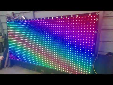
Better videos. The end of the 2nd video shows the pixel display from the rear. Keep in mind this display is 4 feet tall and 8 feet wide. It draws almost 800 watts (measured) when fully illuminated white at the highest output. Quite frankly, I am unsure why the power supplies didn't shutdown when I tried that. It really lit up the back yard!
Looks very nice 👍
@ke4pjw Nice project!
Do you think your Wiznet code would work with this other module from Digikey?
https://www.digikey.com/en/products/detail/wiznet/wiz850io/8789619
I made a little Eval adapter for it:
@Rayman Thanks! The I/O would need to be changed from parallel to serial, but yes, it should work. Some of the constants may need to be changed to whatever the W5500 uses. The initialization may be different, but I think most of those Wiznet chips are very, very similar. I feel foolish for going with the W6100 instead of the W5500 or W5700, but it had the best documentation. At least I am now very familiar with how it all works with those chipsets. Its standout feature was that it supports IPv6, which I didn't implement, LOL. Live and learn.
Ok, then I'll have to see what I can "borrow", thanks!
I was wishing I'd gotten the W6100 version: https://www.wiznet.io/product-item/wiz610io/
But, it doesn't seem to be for sale anywhere...
Don't care about IPv6, but I like that you don't need a crossover cable to connect two together thanks to Auto MDIX.
@Rayman I ordered directly from Wiznet I have a tray of these for my boards, and I also have 20 raw chips, if you would like a couple.
My code is super sloppy. It does not need a dedicated cog. It uses locks to access the Wiznet. There is code for a dedicated cog for my E1.31 decoder, but isn't needed. It's in the W6100.spin2 file.
https://griswoldfx.visualstudio.com/_git/Blitzen 24?path=/W6100drv.spin2
Christmas is saved! Yay! I found what was mostly causing my pixel glitch.
I found that if I just touched the CS line on the Wiznet 6100, glitching would almost all but disappear. I added a .1uf cap on that line, but it caused issues with the browser code and also would not correctly setup the port speed to 10Mbps in the Wiznet. (This was a full hour of head scratching) This made me to look at my code in W6100.writereg(). I found I did not have appropriate delays when any of my code called the writereg() method.
I am sure there are other bugs related to this as well, but at 1:20AM standing on a step stool, on my front porch holding a laptop with Proptool open, I finally have no glitches on my house, regardless of how "bright" I have the pixels. I have been chasing this for months when I had a moment or two. Running the display glitch free was a beautiful thing!
In need to make sure that my locks are working correctly and take some real measurements on the write timings. Currently the webserver isn't very happy when the E1.31 receiver if "drinking from the firehose" so to speak. It transmits garbled data. I highly suspect it has everything to do with timings in that routine.
Winter is coming........and this year it's 100% Propeller Powered.