I must have forgot to comment that at some point. I remember someone helping me do a better job of the 24bit RGB to 565 format. I will get this updated in the repo this weekend. I am glad you found that code useful. I first did that on the P1 like 10 years ago.
@Rayman said:
@ke4pjw I'm using your OLED code for the Parallax OLED display. Thanks for posting that!
I did just find one thing that might be an error? Or, at least threw me off...
Had to modify these functions as shown below to get the oled to show an image correctly:
So I have started on version 2 of the light controller. There were problems with my layout in V1 Specifically, there were problems with crosstalk. Another problem with V1 of the light controller is burn-in of the OLED. I am going to add a quadrature encoded knob that has a push switch. This will allow navigation of a menu on the OLED as well as allowing the OLED to go to sleep and be awakened when the knob manipulated.
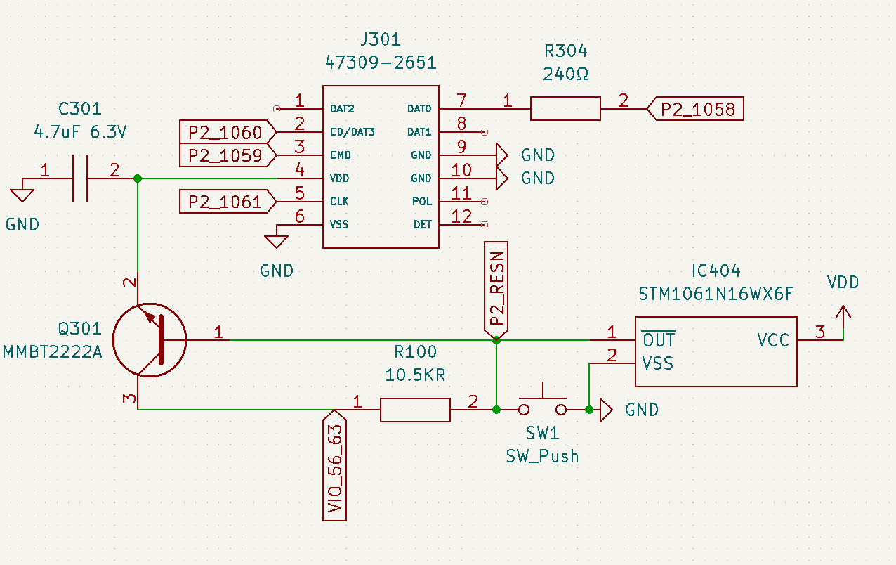
Additionally, there were problems with the hardware reset and the use of the SD card. I will be modifying the reset circuit as outlined below. I wanted to get feedback from other forum members if they see any issues going this route. It should allow for power cycling the SD card during brownout and pressing the reset button, while also placing the P2 into a reset condition.
This is the circuit I'm using on a home-brew accessory board. I use a PFET to switch power through a pin. The pull-up on the gate turns off the SD during reset so you have to pull the PWR\ pin low with code to turn it back on.
@JonnyMac said:
This is the circuit I'm using on a home-brew accessory board. I use a PFET to switch power through a pin. The pull-up on the gate turns off the SD during reset so you have to pull the PWR\ pin low with code to turn it back on.
Thanks for sharing, Jon! Unfortunately, that won't work in my circumstance. I am only going to have SD on the board and will boot from that. Power to the card will have to be available at power on and off with brownout/reset. I may have a look at that FET though. I just chose the SMT equivalent of the 2n2222 because it is "what I know".
Check my thoughts: Add a second PFET with the gate connected to reset. When reset is low, Q2 will conduct and put 3.3v on the gate of Q1 which will kill the power to the SD and its IO pull-ups. When reset is released high, Q2 will shut off allowing R3 to pull the gate of Q1 low which will allow Q1 to provide power to the SD. Does that seem correct?
Maybe -- my guts tell me it's best to switch the 3.3v to the uSD, not ground, which is why I used a PFET. I my have gone overboard with pull-ups. I just looked at the uSD schematic for the Flipper Zero (which I haven't had time to play with...) and it indicates that [my] R5, R6, and R7 (? - this connects to CS\, I will probably keep it) and not needed.
I would think you can switch the 3.3v with a NFET. I don't know FETs well, I am assuming a NFET would act like a NPN transistor. It just means that it would require voltage present at the gate to be "on". This should happen under normal operating conditions. When you press reset or have a brownout condition, it would cause the output of the pull-up to be pulled low, and turn off the 3.3v to the SD card. Just as I did with the NPN transistor above.
I'm a simple guy; with NPNs and N-FETs I always keep the load between the collector/drain and source voltage -- probably so I'm absolutely sure about Vbe or Vgs.
You can use a little 3.3V voltage regulator with an Enable pin. Then just connect ResN of the P2 to the Enable of the regulator.
It's the same size as a FET and also about the same price. And it has the advantage that the SD card gets its own regulator which may lower the noise on the VIOs of the P2. Vin of the regulator should be connected to 5V.
I also like the regulator idea, but would add another part to my BOM, so probably wouldn't use it.
But, does raise question about how much current uSD needs.
I'm thinking 150 mA would be plenty...
500 mA would probably melt the thing...
@Rayman You might like to follow the SD pin mapping that I used and @evanh is using to code his driver if your pins are being otherwise assigned in an arbitrary order. That way at least this driver might be compatible with your board too one day down the track. I think there were pin distance issues otherwise if Smartpins get used. For a pure bitbanging driver though it probably shouldn't matter.
For current I think a 200mA budget should be fine, although it will be card dependent as well as clock speed. If you want to use a small pFET solution you can get a dual package and parallel the FETs like I did to save space. I don't think I saw much over 100-150mA or so anyway. Just don't pick a FET with a large Rds as there will be some voltage drop at high currents which you'll want to constrain. Otherwise a regulator is a good choice too if you can afford one on the board as long as you can power it off. In my own circuit I found the CD signal to be a good way to both let me control the power automatically or manually, as well as letting me detect the card - it's a double duty pin. This can then free an IO pin in a block of 8 and then lets you use it purely as an activity LED and/or for other Smartpin capabilities related to high speed transfers.
@Ariba The use of a regulator is a brilliant idea! @JonnyMac The BU33SD5WG is PERFECT!
Thank you all! I suppose the regulator should be driven by the output of the 3.6V switcher circuit. Just like the other LDOs I am placing on the board.
Wonder why they use OLEDs for small displays like that now. They seem more expensive than LCDs and I doubt so many people care about the contrast ratio on their random appliances. The real crime is that they stopped making VFDs, anyways...
@ke4pjw said:
@Ariba The use of a regulator is a brilliant idea! @JonnyMac The BU33SD5WG is PERFECT!
Thank you all! I suppose the regulator should be driven by the output of the 3.6V switcher circuit. Just like the other LDOs I am placing on the board.
Maybe this one, TCR2EF33,LM(CTfrom Toshiba, will suffice ? It's substantially cheaper.
I use the 3,6V version which allows for a full ADC (or any analog function) range to be used on many micros (not suitable if you're going to use the 3,6V as a main voltage obviously).
Maybe this one, TCR2EF33,LM(CT from Toshiba, will suffice ? It's substantially cheaper.
According to the internet -- where everything can believed -- the current for a uSD should ball between 20 and 100mA.
Same size, too, so I'm going to try it in my P2 uSD accessory board. Thanks for the tip.


Comments
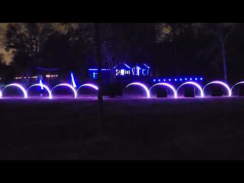
Here is a quick video with about 90% of my lights up. This is a Halloween Sequence. Every light you see here is controlled by a P2 or a P1.
Cool stuff.
I admire the work that went to this effect. .
.
While I'm not much into lights I am very much in favour of, your words exacltly, "controlled buy"
LOL. I never won the spelling contest")
@ke4pjw I'm using your OLED code for the Parallax OLED display. Thanks for posting that!
I did just find one thing that might be an error? Or, at least threw me off...
Had to modify these functions as shown below to get the oled to show an image correctly:
PUB R24bitColor(RGB): rt return (((RGB & $F800) >> 11))<<1' * 527 + 23 ) >> 6 PUB G24bitColor(RGB): rt return (((RGB & $7E0) >> 5))' * 259 + 33 ) >> 6 PUB B24bitColor(RGB): rt return ((RGB & $1F) )<<1'* 527 + 23 ) >> 6Hey Ray! It has been a while since I actually tested a 24bit image. I usually convert to a raw 565 16bit format. The repo is here: https://griswoldfx.visualstudio.com/P2 SSD1331
I must have forgot to comment that at some point. I remember someone helping me do a better job of the 24bit RGB to 565 format. I will get this updated in the repo this weekend. I am glad you found that code useful. I first did that on the P1 like 10 years ago.
Ada told me about the rgbsqz instruction that handles 24-bit (8:8:8) to 16-bit 5:6:5.
pub rgb24to565(rgb) : result '' Create 16-bit (5:6:5) value from 24-bit rgb ($00RRGGBB) org mov result, rgb shl result, #8 rgbsqz result endSo I have started on version 2 of the light controller. There were problems with my layout in V1 Specifically, there were problems with crosstalk. Another problem with V1 of the light controller is burn-in of the OLED. I am going to add a quadrature encoded knob that has a push switch. This will allow navigation of a menu on the OLED as well as allowing the OLED to go to sleep and be awakened when the knob manipulated.
Additionally, there were problems with the hardware reset and the use of the SD card. I will be modifying the reset circuit as outlined below. I wanted to get feedback from other forum members if they see any issues going this route. It should allow for power cycling the SD card during brownout and pressing the reset button, while also placing the P2 into a reset condition.
Thanks,
--Terry
This is the circuit I'm using on a home-brew accessory board. I use a PFET to switch power through a pin. The pull-up on the gate turns off the SD during reset so you have to pull the PWR\ pin low with code to turn it back on.
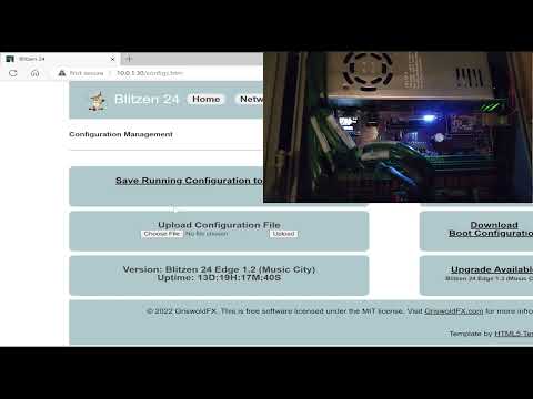
Didn't know OLED could burn in .... Have to watch out for that...
I didn't either. This was after about 6 months use. (1 minute 50 second mark)
Thanks for sharing, Jon! Unfortunately, that won't work in my circumstance. I am only going to have SD on the board and will boot from that. Power to the card will have to be available at power on and off with brownout/reset. I may have a look at that FET though. I just chose the SMT equivalent of the 2n2222 because it is "what I know".
Check my thoughts: Add a second PFET with the gate connected to reset. When reset is low, Q2 will conduct and put 3.3v on the gate of Q1 which will kill the power to the SD and its IO pull-ups. When reset is released high, Q2 will shut off allowing R3 to pull the gate of Q1 low which will allow Q1 to provide power to the SD. Does that seem correct?
Can this be accomplished with a single NFET and a single pullup (shared with the brownout circuit)? I am trying to also minimize component count.
Maybe -- my guts tell me it's best to switch the 3.3v to the uSD, not ground, which is why I used a PFET. I my have gone overboard with pull-ups. I just looked at the uSD schematic for the Flipper Zero (which I haven't had time to play with...) and it indicates that [my] R5, R6, and R7 (? - this connects to CS\, I will probably keep it) and not needed.
I would think you can switch the 3.3v with a NFET. I don't know FETs well, I am assuming a NFET would act like a NPN transistor. It just means that it would require voltage present at the gate to be "on". This should happen under normal operating conditions. When you press reset or have a brownout condition, it would cause the output of the pull-up to be pulled low, and turn off the 3.3v to the SD card. Just as I did with the NPN transistor above.
I'm a simple guy; with NPNs and N-FETs I always keep the load between the collector/drain and source voltage -- probably so I'm absolutely sure about Vbe or Vgs.
This is what I had made. Haven't tested it yet though...
Also, designed rather hastily...
I seem to recall somebody else, @rogloh perhaps, also working on a full breakout...
Found it: https://forums.parallax.com/discussion/174988/new-sd-mode-p2-accessory-board/p1
You can use a little 3.3V voltage regulator with an Enable pin. Then just connect ResN of the P2 to the Enable of the regulator.
It's the same size as a FET and also about the same price. And it has the advantage that the SD card gets its own regulator which may lower the noise on the VIOs of the P2. Vin of the regulator should be connected to 5V.
Andy
That's a neat idea, Andy. Since I'm re-spinning my P2 Accessory uSD board, I think I may change my P-FET to a regulator.
@ke4pjw : I used this regulator on a convention badge a few years ago; it's small and has enough oomph for a uSD card.
I also like the regulator idea, but would add another part to my BOM, so probably wouldn't use it.
But, does raise question about how much current uSD needs.
I'm thinking 150 mA would be plenty...
500 mA would probably melt the thing...
@Rayman You might like to follow the SD pin mapping that I used and @evanh is using to code his driver if your pins are being otherwise assigned in an arbitrary order. That way at least this driver might be compatible with your board too one day down the track. I think there were pin distance issues otherwise if Smartpins get used. For a pure bitbanging driver though it probably shouldn't matter.
For current I think a 200mA budget should be fine, although it will be card dependent as well as clock speed. If you want to use a small pFET solution you can get a dual package and parallel the FETs like I did to save space. I don't think I saw much over 100-150mA or so anyway. Just don't pick a FET with a large Rds as there will be some voltage drop at high currents which you'll want to constrain. Otherwise a regulator is a good choice too if you can afford one on the board as long as you can power it off. In my own circuit I found the CD signal to be a good way to both let me control the power automatically or manually, as well as letting me detect the card - it's a double duty pin. This can then free an IO pin in a block of 8 and then lets you use it purely as an activity LED and/or for other Smartpin capabilities related to high speed transfers.
@Ariba The use of a regulator is a brilliant idea! @JonnyMac The BU33SD5WG is PERFECT!
Thank you all! I suppose the regulator should be driven by the output of the 3.6V switcher circuit. Just like the other LDOs I am placing on the board.
Blue OLED burn in faster than orange on the two color cheap displays i have
Wonder why they use OLEDs for small displays like that now. They seem more expensive than LCDs and I doubt so many people care about the contrast ratio on their random appliances. The real crime is that they stopped making VFDs, anyways...
Maybe this one, TCR2EF33,LM(CTfrom Toshiba, will suffice ? It's substantially cheaper.
I use the 3,6V version which allows for a full ADC (or any analog function) range to be used on many micros (not suitable if you're going to use the 3,6V as a main voltage obviously).
According to the internet -- where everything can believed -- the current for a uSD should ball between 20 and 100mA.
Same size, too, so I'm going to try it in my P2 uSD accessory board. Thanks for the tip.
Finally got a good video to share. Not a Christmas song, but I play it anyway")
These P2s are hella good pixel pushers. Sequence is 40FPS.
Be sure Youtube is in 1080P for the best quality.
The face is funny, congrats!
Was just testing my p-fet controlled uSD power and uSD works even with FET not enabled.
Guess it's getting power from the I/O pins?
This is strange...
Ok, seems I have to explicitly control the P-FET gate pin. Letting it float gives uSD enough power to run...
Anyway, power circuit seems to work.