@Rayman said:
Was wondering if one could just use up some smart pins to do sample rate conversion...
Have one pin output at say 55 kHz with DAC and another pin do say 32 kHz ADC.
Might even be able to do both with one pin, if I'm seeing it right...
No, I don't think it can do it with one pin. You can have dumb DAC and ADC at the same time, but not the DAC/ADC smart modes. Also, quality might be poo doing that.
Anyways, I just found out that my TV just does not care. It just takes any rate, as it were. It just has to match the clock packet exactly (no sound at all when mismatched). Interestingly, it does seem to pass the oddball rate (or some sort of flag?) on to its SPDIF output (which is weird on account of it never doing that for dolby bitstreams and the like) and the amplifier that goes to gets pissy and doesn't want to do any of its effect modes when the 53kHz signal is active.
Here's a test that does this (there's supposed to be no picture because RAM shortage).
Ok, I've implemented the basic linear interpolation (and all the framework around it to eliminate clock drift) and wow it sounds like hot donkey (compare to the analog outputs on 30/31 or load this same vgm into the 53kHz test posted above). That exquisite "rusty watering can" sound stage.
If you want extra crust, try going to line 240 and replace resample_phase_frac with #0
@Wuerfel_21 said:
Something interesting I just noticed: none of the 32kHz test files actually indicate 32kHz in the channel status word. I left it at 44.1kHz. Seems it doesn't matter?
I think it would depend on how the sink works - it might be possible to derive from the values in the clock regen packets. But why send it if it is unused? Doesn't make sense, so it's likely expected. This is where I was confused myself when trying to figure out my own problems with my TV.
What would be useful would be a way to use the P2 streamer to capture the data from a working source and examine the bits. In my experiments I could already log my own output but needed a reference to compare against. At one point I was thinking I could somehow source the P2 xtal input from the HDMI clock and set the PLL multiplier to 10 or something to sample at 270MHz and hope for the best the sampling would read valid bits. Then a decoder program could be used to check the data against what I was sending and find my audio differences.
@rogloh said:
I think it would depend on how the sink works - it might be possible to derive from the values in the clock regen packets. But why send it if it is unused? Doesn't make sense, so it's likely expected. This is where I was confused myself when trying to figure out my own problems with my TV.
The spec says it needs to be there, but quite honestly, I think they just decided to wrap around S/PDIF for some reason and "uhh I guess you need to set the channel status properly". The clock regen packets are the only thing that will tell you the real rate (my TV seems to stop liking the signal when there's even a minor mismatch with this - 1% is more than enough to throw it off. The resampling driver I posted maintains perfect rational relationship to sysclk to not run afoul of things like that)
Also, I think you skipped all the posts on page 3.
What would be useful would be a way to use the P2 streamer to capture the data from a working source and examine the bits. In my experiments I could already log my own output but needed a reference to compare against. At one point I was thinking I could somehow source the P2 xtal input from the HDMI clock and set the PLL multiplier to 10 or something to sample at 270MHz and hope for the best the sampling would read valid bits. Then a decoder program could be used to check the data against what I was sending and find my audio differences.
Yeah, I was thinking that you could probably get a bit closer by analyzing the signal from a "real" source. Though I was thinking more like "expensive logic analyzer".
Another silly idea: If I'm already reformatting the audio for clean digital output, wonder if I could add simultaneous S/PDIF output (or have it as an option when doing analog video)
Annoyingly, there's no good smart mode for this. P_ASYNC_TX could be used if I sacrifice the LSB to fudge the parity in the first half-sample such that the start and stop bits line up with what we need. The bit period needs to be exactly 1/128th of the sample period, which I think the async tx mode can do. Would also need to poll that one very often.
@Rayman said:
S/PDIF output would be awesome addition. Imagine drop dead easy compared to hdmi
Not really. The biggest problem with the hdmi audio is just understanding how the data actually needs to be packaged up. The actual code isn't so bad and you can just clock the data out in the video blanking period. S/PDIF doesn't have a good smartpin mode to drive it and needs to be babysat more often (4x sample rate)
@Wuerfel_21 said:
The spec says it needs to be there, but quite honestly, I think they just decided to wrap around S/PDIF for some reason and "uhh I guess you need to set the channel status properly". The clock regen packets are the only thing that will tell you the real rate (my TV seems to stop liking the signal when there's even a minor mismatch with this - 1% is more than enough to throw it off. The resampling driver I posted maintains perfect rational relationship to sysclk to not run afoul of things like that)
I will have try it again to see if it helps with my audio issue. It might have been very picky on timing too. The valid channel status thing might be so all sinks could just output S/PDIF as well with less reprocessing needed.
Also, I think you skipped all the posts on page 3.
Yep, realized there was more after posting so quoted you in an edit. My mistake.
Yeah, I was thinking that you could probably get a bit closer by analyzing the signal from a "real" source. Though I was thinking more like "expensive logic analyzer".
Nice if you have one...
Another silly idea: If I'm already reformatting the audio for clean digital output, wonder if I could add simultaneous S/PDIF output (or have it as an option when doing analog video)
Annoyingly, there's no good smart mode for this. P_ASYNC_TX could be used if I sacrifice the LSB to fudge the parity in the first half-sample such that the start and stop bits line up with what we need. The bit period needs to be exactly 1/128th of the sample period, which I think the async tx mode can do. Would also need to poll that one very often.
@Wuerfel_21 said:
Ok, I've implemented the basic linear interpolation (and all the framework around it to eliminate clock drift) and wow it sounds like hot donkey (compare to the analog outputs on 30/31 or load this same vgm into the 53kHz test posted above). That exquisite "rusty watering can" sound stage.
If you want extra crust, try going to line 240 and replace resample_phase_frac with #0
And of course I just realized that I forgot another debug line in the code. And I thought the difference was very small. The linear interpolation never worked because line 242 breaks it. Owie. Probably is a bit less donkey when you remove that. But no more testing on the TV today...
May actually throw in the towel on the high-quality resampling. The fixed linear resampling is uhh... good enough maybe. And the sinc stuff is slow and I couldn't get it to work properly. Maybe with a different source, but this OPN2 stuff is so distorted to begin with that maybe it really doesn't matter. Everything will be fine for sources with standard rates.
And now with pixel doubling. The idea is to just change the code to call into a function pointer with at most 11 other instructions going inbetween. During active scan this function pumps the streamer with two pixels, during blanking it's just a RET. Also need to keep track of how often this got called so the line can be finished with the correct pixel count.
Clever folks might realize that in 8bpp palette mode, one actually can stuff more than 2 pixels at a time. RGB modes can't do that, so I made it match. Though one could certainly do smth. like text font tiles with this without changing the build_audio code.
(Also, yes, I didn't make it double vertically, so everything is 2x1 pixels and the bottom of the screen is junk. Changing that would be trivial and I semi-intentionally didn't do it here)
As usual can't hear anything on my HDMI setups with these test programs (was sorta hoping if you got CTS/N params spot on it might suddenly work), but I can see your pixel doubling working at least. LOL.
Another idea: I still haven't wired in that 5V line on the Parallax HDMI board as video was already working without it on all my devices. Would be laughable if that was the only problem that prevented the thing from working this entire time - will have to jumper in a resistor to check this out too.
@rogloh said:
Another idea: I still haven't wired in that 5V line on the Parallax HDMI board as video was already working without it on all my devices. Would be laughable if that was the only problem that prevented the thing from working this entire time - will have to jumper in a resistor to check this out too.
I'm actually just using one of those not-dupont breadboard wires, lodged in those pin holes. Kinda wobbly, but no picture without that and I'm too lazy to solder it.
@Rayman said:
Was just looking at the 1 kHz code to see how to make it play .wav files....
Looks to me like just need to get audio samples into tmp1 here: getqx tmp1
Instead of the qrotated value. Is that close to being correct?
Yes, very correct. Obvious caveat: this is mono only. You'll notice it duplicates the value twice into the subpacket. The subpacket is 8 bytes: 3 bytes (24 bit) of left sample, another 3 bytes of right sample, one byte with channel status and parity for both channels and a CRC byte (calculated later). These all are stuffed into two longs the usual way. See HDMI spec for more.
Unrelatedly, does the scan2x version from earlier work for you?
@Wuerfel_21 said:
May actually throw in the towel on the high-quality resampling. The fixed linear resampling is uhh... good enough maybe. And the sinc stuff is slow and I couldn't get it to work properly.
What about polynomial interpolation? I don't know much about audio sampling theory but I do a lot of interpolation stuff in motion control. There, it helps a lot to get rid of the "jerks" by smoothening out the velocity and acceleration profiles which are the first and second derivative of position. So I thuink if you do a quadratic or cubic interpolation instead of a linear one it should reduce the aliasing affects a lot.
Cubic is sometimes used for audio. Might want to have a look at how that goes. If that's doable with just some MULS that'd be great. Though the nice thing about the sinc algorithm is that it does lowpass filtering at the same time as it resamples. Now, the OPN2 cog already has a simple one-pole IIR lowpass filter built-in, not sure how steep the 8-point sinc filter really is and what it adds there (larger sinc filters become very steep)
Wrote up the cubic function. It doesn't really do much to stop the primary aliasing (that bright line that is directly "connected" to the actual signal), but all the other junk gets reduced a good bit. Thanks for the push @ManAtWork .
Here's linear again for comparsion
code is nice and compact (u is fractional sample position, abcd are 16 bit signed samples):
PUB cubic(u,a,b,c,d) : r | u1,u2,u3, tmp,tmp2
asm
              mov u1,u
              shr u1,#16

              mov u2,u1
              mul u2,u1
              shr u2,#16

              mov u3,u2
              mul u3,u1
              shr u3,#16

              mov tmp,u3
              sub tmp,u2
              sub tmp,u2
              add tmp,u1
              sar tmp,#2
              muls tmp,a
              mov r,tmp

              mov tmp,u3
              mul tmp,#3
              mov tmp2,u2
              mul tmp2,#5
              subr tmp,tmp2
              sub tmp,##$20000
              sar tmp,#2
              muls tmp,b
              add r,tmp

              mov tmp,u3
              mul tmp,#3
              mov tmp2,u2
              mul tmp2,#4
              sub tmp,tmp2
              sub tmp,u1
              sar tmp,#2
              muls tmp,c
              add r,tmp

              neg tmp,u3
              add tmp,u2
              sar tmp,#2
              muls tmp,d
              add r,tmp

              sar r,#15
              neg r
              fges r,##-$8000
              fles r,##$7FFF
endasm
One may notice the negations going on to avoid overflow (because +1.0 is not a valid value, but -1.0 is). There's a bit of rounding error (when a=b=c=d the output isn't always correct), though the SAR at the end can be tweaked to get 24bit output, which presumably solves that issue. Most of this is just calculating coefficients, so doing it in stereo would be super cheap.
The instruction count could also be reduced by shuffling the code a bit (u3*3 is calculated twice and u2*4 could be kept around to calculate u2*5)
You must have somehow switched them. I just reconfirmed with fresh downloads from the forum. opn2test_top-2023-11-21 should have all garbage screen and opn2test_scan2x should have the half-screen shown above. Which doesn't have sound for you again?
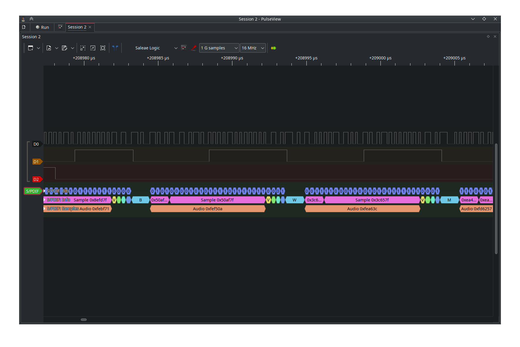
I figured out why previous SPDIF-themed experiments didn't work out: P_ASYNC_TX only raises the IN flag when it is done sending a word, it is low if you just started up the pin and haven't sent anything yet.
Now appears to show up fine on the ol' analyzer at least
My oldest pasm Tx debug code has a test of both IN and the RDPIN carry flag to handle that and fully make use of the hardware buffering.
putch
        rqpin   inb, #DIAGTXPIN  wc 'transmiting? (C high == yes)  *Needed to initiate tx
        testp   #DIAGTXPIN  wz      'buffer free? (IN high == yes)
if_nc_or_z  wypin   pb, #DIAGTXPIN      'write new byte to Y buffer
if_nc_or_z  ret wcz         'restore C/Z flags of calling routine
        jmp #putch          'wait while Smartpin is both full (nz) and transmitting (c)
@evanh said:
My oldest pasm Tx debug code has a test of both IN and the RDPIN carry flag to handle that and fully make use of the hardware buffering.
I just did a dummy WYPIN on startup to get it going
Hooked it up to the next-best 5.1 amp box thing (notably not the upstairs Yamaha, but my basement Pioneer). Yep, sure is playing audio.
Caveats:
does 75Ohm 1V p-p S/PDIF on pin 25 using BITDAC. Can wire that straight from the A/V accessory into a coax input. Would need different setting for driving an LED transmitter.
LSB of each sample gets overwritten with garbage to work around smartpin limitations (hey @cgracey, something to add to the silicon bug list - allow async tx without implicit start/stop bits)
video output has been disabled for testing
still has the linear resampler and is lacking other niceties developed in the scan2x version
sometimes plays awful static before VGM playback starts (Doesn't come out on the DAC output and didn't happen in any HDMI versions, so idk what's happening. Maybe it's because all YM2612 registers get cleared to zero on startup and that creates some sort of DC bias that causes confusion with the 5.1 box. Should probably figure out real reset values. Zero is probably not right since TL=0 actually means max volume. I already did a band-aid fix to always initialize pan bits to 1 ).


Comments
No, I don't think it can do it with one pin. You can have dumb DAC and ADC at the same time, but not the DAC/ADC smart modes. Also, quality might be poo doing that.
Anyways, I just found out that my TV just does not care. It just takes any rate, as it were. It just has to match the clock packet exactly (no sound at all when mismatched). Interestingly, it does seem to pass the oddball rate (or some sort of flag?) on to its SPDIF output (which is weird on account of it never doing that for dolby bitstreams and the like) and the amplifier that goes to gets pissy and doesn't want to do any of its effect modes when the 53kHz signal is active.
Here's a test that does this (there's supposed to be no picture because RAM shortage).
Ok, I've implemented the basic linear interpolation (and all the framework around it to eliminate clock drift) and wow it sounds like hot donkey (compare to the analog outputs on 30/31 or load this same vgm into the 53kHz test posted above). That exquisite "rusty watering can" sound stage.
If you want extra crust, try going to line 240 and replace
resample_phase_fracwith#0I think it would depend on how the sink works - it might be possible to derive from the values in the clock regen packets. But why send it if it is unused? Doesn't make sense, so it's likely expected. This is where I was confused myself when trying to figure out my own problems with my TV.
What would be useful would be a way to use the P2 streamer to capture the data from a working source and examine the bits. In my experiments I could already log my own output but needed a reference to compare against. At one point I was thinking I could somehow source the P2 xtal input from the HDMI clock and set the PLL multiplier to 10 or something to sample at 270MHz and hope for the best the sampling would read valid bits. Then a decoder program could be used to check the data against what I was sending and find my audio differences.
The spec says it needs to be there, but quite honestly, I think they just decided to wrap around S/PDIF for some reason and "uhh I guess you need to set the channel status properly". The clock regen packets are the only thing that will tell you the real rate (my TV seems to stop liking the signal when there's even a minor mismatch with this - 1% is more than enough to throw it off. The resampling driver I posted maintains perfect rational relationship to sysclk to not run afoul of things like that)
Also, I think you skipped all the posts on page 3.
Yeah, I was thinking that you could probably get a bit closer by analyzing the signal from a "real" source. Though I was thinking more like "expensive logic analyzer".
Another silly idea: If I'm already reformatting the audio for clean digital output, wonder if I could add simultaneous S/PDIF output (or have it as an option when doing analog video)
Annoyingly, there's no good smart mode for this. P_ASYNC_TX could be used if I sacrifice the LSB to fudge the parity in the first half-sample such that the start and stop bits line up with what we need. The bit period needs to be exactly 1/128th of the sample period, which I think the async tx mode can do. Would also need to poll that one very often.
S/PDIF output would be awesome addition. Imagine drop dead easy compared to hdmi
Not really. The biggest problem with the hdmi audio is just understanding how the data actually needs to be packaged up. The actual code isn't so bad and you can just clock the data out in the video blanking period. S/PDIF doesn't have a good smartpin mode to drive it and needs to be babysat more often (4x sample rate)
I will have try it again to see if it helps with my audio issue. It might have been very picky on timing too. The valid channel status thing might be so all sinks could just output S/PDIF as well with less reprocessing needed.
Yep, realized there was more after posting so quoted you in an edit. My mistake.
Nice if you have one...
Could be interesting. I was able to get some S/PDIF output from a P2 in this thread but made use of scanlime's P1 work ported to run on the P2 which needed its own COG. I used P_SYNC_TX I think.
https://forums.parallax.com/discussion/comment/1546491/#Comment_1546491
And of course I just realized that I forgot another debug line in the code. And I thought the difference was very small. The linear interpolation never worked because line 242 breaks it. Owie. Probably is a bit less donkey when you remove that. But no more testing on the TV today...
May actually throw in the towel on the high-quality resampling. The fixed linear resampling is uhh... good enough maybe. And the sinc stuff is slow and I couldn't get it to work properly. Maybe with a different source, but this OPN2 stuff is so distorted to begin with that maybe it really doesn't matter. Everything will be fine for sources with standard rates.
So yea, here's that fixed (and slightly cleaned up) version with linear interpolation...
At least this one is simple enough that I could probably do pixel doubling without using a buffer (just interleaving xconts into the code)...
Also tried to see what's popping in SPDIF land, not much so far.
And now with pixel doubling. The idea is to just change the code to call into a function pointer with at most 11 other instructions going inbetween. During active scan this function pumps the streamer with two pixels, during blanking it's just a RET. Also need to keep track of how often this got called so the line can be finished with the correct pixel count.
Clever folks might realize that in 8bpp palette mode, one actually can stuff more than 2 pixels at a time. RGB modes can't do that, so I made it match. Though one could certainly do smth. like text font tiles with this without changing the
build_audiocode.(Also, yes, I didn't make it double vertically, so everything is 2x1 pixels and the bottom of the screen is junk. Changing that would be trivial and I semi-intentionally didn't do it here)
As usual can't hear anything on my HDMI setups with these test programs (was sorta hoping if you got CTS/N params spot on it might suddenly work), but I can see your pixel doubling working at least. LOL.
Another idea: I still haven't wired in that 5V line on the Parallax HDMI board as video was already working without it on all my devices. Would be laughable if that was the only problem that prevented the thing from working this entire time - will have to jumper in a resistor to check this out too.
I'm actually just using one of those not-dupont breadboard wires, lodged in those pin holes. Kinda wobbly, but no picture without that and I'm too lazy to solder it.
Yeah I just did the same. I don't want to solder it right now. No improvement
The first "opn2test_top-2023-11-21" I get half large picture an garbage on the second half of the screen and no sound
The second garbage picture rows on whole screen with nice sound
Are you mixing the two up? The earlier non-"scan2x" one is the one that should show just garbage.
Was just looking at the 1 kHz code to see how to make it play .wav files....
Looks to me like just need to get audio samples into tmp1 here:
getqx tmp1Instead of the qrotated value. Is that close to being correct?
Yes, very correct. Obvious caveat: this is mono only. You'll notice it duplicates the value twice into the subpacket. The subpacket is 8 bytes: 3 bytes (24 bit) of left sample, another 3 bytes of right sample, one byte with channel status and parity for both channels and a CRC byte (calculated later). These all are stuffed into two longs the usual way. See HDMI spec for more.
Unrelatedly, does the scan2x version from earlier work for you?
What about polynomial interpolation? I don't know much about audio sampling theory but I do a lot of interpolation stuff in motion control. There, it helps a lot to get rid of the "jerks" by smoothening out the velocity and acceleration profiles which are the first and second derivative of position. So I thuink if you do a quadratic or cubic interpolation instead of a linear one it should reduce the aliasing affects a lot.
Cubic is sometimes used for audio. Might want to have a look at how that goes. If that's doable with just some MULS that'd be great. Though the nice thing about the sinc algorithm is that it does lowpass filtering at the same time as it resamples. Now, the OPN2 cog already has a simple one-pole IIR lowpass filter built-in, not sure how steep the 8-point sinc filter really is and what it adds there (larger sinc filters become very steep)
Wrote up the cubic function. It doesn't really do much to stop the primary aliasing (that bright line that is directly "connected" to the actual signal), but all the other junk gets reduced a good bit. Thanks for the push @ManAtWork .
Here's linear again for comparsion
code is nice and compact (u is fractional sample position, abcd are 16 bit signed samples):
PUB cubic(u,a,b,c,d) : r | u1,u2,u3, tmp,tmp2 asm mov u1,u shr u1,#16 mov u2,u1 mul u2,u1 shr u2,#16 mov u3,u2 mul u3,u1 shr u3,#16 mov tmp,u3 sub tmp,u2 sub tmp,u2 add tmp,u1 sar tmp,#2 muls tmp,a mov r,tmp mov tmp,u3 mul tmp,#3 mov tmp2,u2 mul tmp2,#5 subr tmp,tmp2 sub tmp,##$20000 sar tmp,#2 muls tmp,b add r,tmp mov tmp,u3 mul tmp,#3 mov tmp2,u2 mul tmp2,#4 sub tmp,tmp2 sub tmp,u1 sar tmp,#2 muls tmp,c add r,tmp neg tmp,u3 add tmp,u2 sar tmp,#2 muls tmp,d add r,tmp sar r,#15 neg r fges r,##-$8000 fles r,##$7FFF endasmOne may notice the negations going on to avoid overflow (because +1.0 is not a valid value, but -1.0 is). There's a bit of rounding error (when a=b=c=d the output isn't always correct), though the SAR at the end can be tweaked to get 24bit output, which presumably solves that issue. Most of this is just calculating coefficients, so doing it in stereo would be super cheap.
The instruction count could also be reduced by shuffling the code a bit (u3*3 is calculated twice and u2*4 could be kept around to calculate u2*5)
Will see to put it into the HDMI code tomorrow.
Just tested with my lowish cost FireTv and it does play music. Image on top of screen and junk below. This is really nice work @Wuerfel_21 !
pict of half frame on opn2test_top-2023-11-21
You must have somehow switched them. I just reconfirmed with fresh downloads from the forum.
opn2test_top-2023-11-21should have all garbage screen andopn2test_scan2xshould have the half-screen shown above. Which doesn't have sound for you again?Anyways, here's a new version
This one works,
Picture is pixelated as expected. Sound is running
I figured out why previous SPDIF-themed experiments didn't work out: P_ASYNC_TX only raises the IN flag when it is done sending a word, it is low if you just started up the pin and haven't sent anything yet.
Now appears to show up fine on the ol' analyzer at least
My oldest pasm Tx debug code has a test of both IN and the RDPIN carry flag to handle that and fully make use of the hardware buffering.
putch rqpin inb, #DIAGTXPIN wc 'transmiting? (C high == yes) *Needed to initiate tx testp #DIAGTXPIN wz 'buffer free? (IN high == yes) if_nc_or_z wypin pb, #DIAGTXPIN 'write new byte to Y buffer if_nc_or_z ret wcz 'restore C/Z flags of calling routine jmp #putch 'wait while Smartpin is both full (nz) and transmitting (c)I just did a dummy WYPIN on startup to get it going")
Hooked it up to the next-best 5.1 amp box thing (notably not the upstairs Yamaha, but my basement Pioneer). Yep, sure is playing audio.
Caveats:
Yep, that is an alternative. I wanted it as an all-in-one back then. That, and the alternative meant the dummy first character went to the terminal.
It is a slight downer that either solution is required. I think it may have been intended for IRQ use. Not sure, I never did do an IRQ version myself.