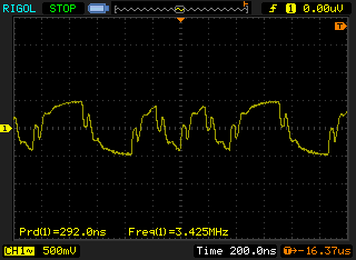
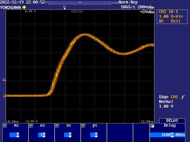
Just tried this...unbelievably it worked and I could playback music to my amp with digital S/PDIF using its coaxial input from the microphone jack of the A/V board. To output the bits I used the 2V 75R bitDAC with 1V and 0V setup for the two logic levels. When driving into 75 ohms this should result in 500mVp-p signal. Here's the pin config I used. The TX clock was the P2 clock divided by 10 and I setup the P2 with_clkfreq = 56_450000.
It's an ugly waveform and the 1uF really rounds off the edges - ideally it should be only a 0.1uF coupling cap. I reckon jitter would be pretty bad. This was captured at the P2 end of the cable. But it played music! Maybe a coax would be cleaner - some of this might be reflections or other cable issues. Although given I'm listening to Cradle of Filth's Dirge Inferno all imperfections are probably being masked by the music itself.
EDIT: Correction to above, that setting should have been this: wrpin ##(P_DAC_75R_2V | $7000 | P_PLUS3_B | P_OE | P_SYNC_TX), param_pin
That was why the captured trace was still 1V p-p.
If you have a P2-EVAL and an A/V board with a coaxial S/PDIF capable AMP/receiver you can try this out too. I've made a demo you can use.
Create or copy an existing WAV file to a FAT32 microSD card and name it "testwav.wav" in the root folder of the card.
I just used VLC to convert another file into this standard output format. Needs to be a regular 44100Hz 16 bit stereo file with a 44 byte RIFF/WAV header before the samples to be recognized by this code. I used this file format info when parsing the file:
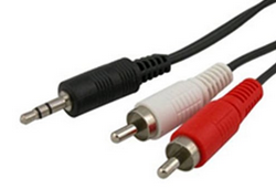
Setup the A/V board on pin 8 (and leave pin 16 free) - or you can modify the BASE_PIN accordingly in the music.spin2 file. Attach a 3.5mm plug to the microphone port and wire the tip's RCA plug (should be left channel - WHITE) on the other end to the coaxial S/PDIF input on your receiver. I made a custom cable but you can probably use one of these common cables you may already have lying about. If it doesn't work on the left channel, you can try the other channel's RCA plug too.
DISCLAIMER: Output levels are setup to put 0.5Vpp into 75ohms and should be safe for your amp but I'm not guaranteeing you won't blow something up if you cable something incorrectly or have bad power supplies, different ground levels etc, or other bad hardware, so you should only try this at your own risk and if you are confident to use this with your potentially expensive audio gear. Also best to start out with the volume levels low - if there are serious receiver bit errors it could possibly send a lot of nasty noise to your speakers.
Plug the SD card into the P2 (don't boot from it or from Flash) and build and load music.binary with flexspin. With any luck the music should begin playing on your receiver. flexspin -2 music.spin2 loadp2 -t music.binary
The baud rate is set to 115200 in the code and some status/error messages are printed to show what is happening.
The P2 system clock is hardcoded to 56.5MHz and this results in 44140Hz playback assuming a perfect 20MHz crystal frequency which won't be the case anyway.
If you have a slow SD card and have problems with the audio you might like to increase the buffer size from $1000 to $8000. My card is a SanDisk Ultra and reads fast so the ping pong audio buffer was set to just 4096 samples or 16kB and this was enough to not underflow (it probably could go even lower).
@rogloh said:
The P2 system clock is hardcoded to 56.5MHz and this results in 44140Hz playback assuming a perfect 20MHz crystal frequency which won't be the case anyway.
If you want a sysclk that is an integer multiple of 5.6448MHz and 20MHz, then 220MHz is the closest. 220MHz / 39 = 5.6410Mhz, which is more accurate than 56.5Mhz / 10 and XI * 11 / 1 should be better than XI * 113 / 40.
Ok but how do you get a divide by 39 in NCO mode? Ideally you want an even number. I set this value as the empirical high/low time interval and $80000000 as the value to add to the counter. This results in a symmetric clock and no extra jitter due to NCO wraparound events etc.
@rogloh said:
Ok but how do you get a divide by 39 in NCO mode? Ideally you want an even number. I set this value as the empirical high/low time interval and $80000000 as the value to add to the counter. This results in a symmetric clock and no extra jitter due to NCO wraparound events etc.
I don't know, I was just trying to help.
@rogloh said:
240MHz is an exact multiple of the 20MHz crystal, so I'd expect it should be cleaner... Later today I hope to try out the S/PDIF from an internal tx clock derived from a clean xtal multiple like this.
This is what led me to spending time looking at exact multiples for you. 260MHz / 46 is next best after 220MHz / 39.
@TonyB_ said:
This is what led me to spending time looking at exact multiples for you. 260MHz / 46 is next best after 220MHz / 39.
Appreciate the efforts. Always using 56.5MHz is certainly not a final solution and was just used for this quick demo. 260 / 46 could be a good one to try for lower PLL jitter and is in the range that could still make a good video clock too.
I feel like you might be worrying about literally nothing. Any decent SPDIF receiver (esp. if it's not just a dumb DAC but some sort of home cinema thing with DSPs inside) should paper over imperfections in the signal clock. I guess a good test would be to deliberately modulate the clock and see when it starts having any sort of effect.
@Wuerfel_21 said:
I feel like you might be worrying about literally nothing. Any decent SPDIF receiver (esp. if it's not just a dumb DAC but some sort of home cinema thing with DSPs inside) should paper over imperfections in the signal clock.
One would hope this would be the case. I was quite surprised given that nasty looking waveform I sent when it still worked! But I was playing loud metal which is not necessarily ideal test material.
I guess a good test would be to deliberately modulate the clock and see when it starts having any sort of effect.
Yeah I still want to try that. Hopefully sometime soon though it's a busy week. Others can always have a go too if they want, now this code is working.
@Wuerfel_21 said:
I feel like you might be worrying about literally nothing. Any decent SPDIF receiver (esp. if it's not just a dumb DAC but some sort of home cinema thing with DSPs inside) should paper over imperfections in the signal clock.
One would hope this would be the case. I was quite surprised given that nasty looking waveform I sent when it still worked! But I was playing loud metal which is not necessarily ideal test material.
Yea. Most "loud" genre music still sounds fine if you convert to 8 bit per sample (plain linear encoding will obviously kill quieter parts / fade-outs, but A-Law can be transparent). Get some lossless classical in there. Helped a lot when writing an audio codec. (noise shaping is hard...)
@rogloh said:
Ok but how do you get a divide by 39 in NCO mode? Ideally you want an even number. I set this value as the empirical high/low time interval and $80000000 as the value to add to the counter. This results in a symmetric clock and no extra jitter due to NCO wraparound events etc.
This is for P_NCO_FREQ (%00110) to produce a clock for the P_SYNC_TX (%11100) serial shifter, right? Just set the X register to 39 to get a divide by 39. Doh! I see, that is half rate, we want a divide by 19.5 ...
Okay, dithered SCLK then? Set X = 13 and Y = $5555_5555
Wish it was as easy as that. With the WYPIN set to $80000000 that 39 is the number of P2 clocks to toggle the output (half period). I'd need to set it to 19.5.
@evanh said:
How about using P_PWM_SAWTOOTH. X = 1 | 39<<16, Y = 19
Yeah that looks promising and would let us try @TonyB_ 's suggested PLL settings. Actually this clock doesn't have to be symmetric either, it's just used for edge detection inside the P2 when transmitting. The other clocks for the I2S do need to be fairly symmetric, at least within 45-55% IIRC.
Update: just tried this clock mode out with P2 running at 220MHz and listened to Billy Idol's Don't need a gun and it was sounding decent on headphones. Will need to check what exactly I transcoded from to see if it was compressed or not to begin with...EDIT: nope, came from an Apple Lossless m4a by the looks of it.
I tried to make a 5.6488 MHz ish clock from a 252MHz P2 but was unable to get a reliable clock.
For some reason P_NCO_FREQ mode using a WXPIN value of 1 and a WYPIN value of 96207267 (which is 2^32 * 5.6488/252) doesn't yield a transmit clock at this rate. There is a lot of jitter on the clock and it looks more like 5MHz on the scope. Audio works but plays slow. What's going on here? What did I get wrong in my settings....?
UPDATE: DOH! hadn't fully saved the file defining the new clock frequency had I - was still running at 220MHz! Ignore the above. It's working now and playing back reasonably cleanly too even with this jittery clock.
Yeah it's quite jittery isn't it. But interestingly it still sounds reasonable (with my music at least). It seems like you can get away with it which is really bizarre to me. Maybe there is some dejitter buffer going on internally inside my gear (though I still need to try it with the HT Marantz and clearer music to see how that compares). If anyone else also has an S/PDIF receiver that accepts coaxial input and is happy to try it out let me know what you think of the sound quality... it's always going to be subjective though isn't it.
I'm not too sure really. I don't know how to quantify it. I've tried this before and again just now - when I increase that post-trigger capture delay to a ridiculously large value like a few hundred microseconds it doesn't increase the width of the jitter any more than 15 μs captures get. In fact I don't know where the limit even is. It might be down at 8 μs say.
Perhaps your scope with a delayed trigger can't accumulate more than certain amount of samples or waveforms and that limits how much jitter gets shown after the delay or the jitter is fully constrained by this point in time and all jitter is being shown and does not increase further. Not sure really either.
It's not limited that way. That delay is the time between trigger condition and start of capture sampling. It'll be sampling all the time but discards until the delay expires.
I want to say the jitter width can be defined in terms of parts-per-million. Eg: The 252 MHz jitter is 0.5 ns wider than the 240 MHz reference over a 15.8 μs period, or 32 ppm. But it doesn't fit so simply with it not scaling with the delay.
If that is true for 8 μs too then maybe it's more correct to say 0.5 ns over 8 μs period, or 64 ppm.
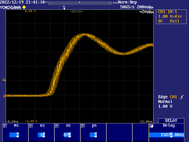
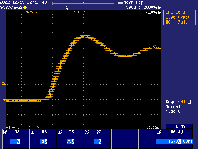
Evan, your graphs are some sort of indication of sysclk jitter? The heights of the peaks and troughs within the waveform appear to increase as PLL divider value increases. What does 260 MHz look like with same settings as last four?
I'm wondering if a new board I'm thinking about and intended mainly for 252 MHz sysclk would be better off with a 12 MHz oscillator.
@TonyB_ said:
Evan, your graphs are some sort of indication of sysclk jitter? The heights of the peaks and troughs within the waveform appear to increase as PLL divider value increases. What does 260 MHz look like with same settings as last four?
That's over/undershoot ringing of the square wave. It's a smartpin outputting P_NCO_FREQ at sysclock/1000. Any trend in the ringing is just a coincidence. If I shift the scope probe's cable it'll probably change shape slightly.
@TonyB_ said:
I'm wondering if a new board I'm thinking about and intended mainly for 252 MHz sysclk would be better off with a 12 MHz oscillator.
Video absolutely doesn't need a precise dot clock. The is lots of leeway in the blanking to use 250 MHz in place of 252 MHz That said, yes, I do think 12 MHz on the XI pin would benefit the stability of a 252 MHz sysclock.
Ah, Tony, when you said peaks and troughs, did you maybe mean the fuzz within the jitter band? I've highlighted in cyan below. The red arrows is what I thought you meant.
The fine trace forming the fuzz is not real at all in that mode of capture. In a normal single pass capture the trace is real but with these captures the sampling that makes a single trace is dispersed over a large number of repeated passes, relying on each repeat of the signal being identical to all the others. Any variation in each pass is recorded as a deviation from the trace centre. The drawing mode, which I can change, then incorrectly links those as an unbroken fine line.
PS: And the duller orange band behind the fuzz is an extra mode of capture where it builds on the multi-pass process to record an even longer history. It accumulates consecutive passes over many seconds, probably millions on top of each other.
Cool. Yeah, sorry, I was thinking in terms of the signal I already understood.
Even without the accumulation mode, at 50 GS/s effective, it must be doing 250 passes (retriggers) of the input signal, at the actual 200 MS/s, to build a single unbroken trace (the bright orange fuzz). So, if there is any non-repeating in the signal for the duration then it'll just make a total mess of the displayed trace.
With accumulation (the dark orange band, or multi-coloured), which can be applied to a single pass trace too, the same effect, of needing a repeating signal, is carried even further.
PS: Each of the 250 passes will have a 20 picosecond delta between each trigger delay timing so as to simulate the 50 GS/s effective sample rate. I have no idea how that is actually achieved.


Comments
Just tried this...unbelievably it worked and I could playback music to my amp with digital S/PDIF using its coaxial input from the microphone jack of the A/V board. To output the bits I used the 2V 75R bitDAC with 1V and 0V setup for the two logic levels. When driving into 75 ohms this should result in 500mVp-p signal. Here's the pin config I used. The TX clock was the P2 clock divided by 10 and I setup the P2 with_clkfreq = 56_450000.
wrpin ##(P_DAC_75R_2V | $F000 | P_PLUS3_B | P_OE | P_SYNC_TX), param_pinIt's an ugly waveform and the 1uF really rounds off the edges - ideally it should be only a 0.1uF coupling cap. I reckon jitter would be pretty bad. This was captured at the P2 end of the cable. But it played music! Maybe a coax would be cleaner - some of this might be reflections or other cable issues. Although given I'm listening to Cradle of Filth's Dirge Inferno all imperfections are probably being masked by the music itself.")
EDIT: Correction to above, that setting should have been this:
wrpin ##(P_DAC_75R_2V | $7000 | P_PLUS3_B | P_OE | P_SYNC_TX), param_pinThat was why the captured trace was still 1V p-p.
If you have a P2-EVAL and an A/V board with a coaxial S/PDIF capable AMP/receiver you can try this out too. I've made a demo you can use.
Create or copy an existing WAV file to a FAT32 microSD card and name it "testwav.wav" in the root folder of the card.
I just used VLC to convert another file into this standard output format. Needs to be a regular 44100Hz 16 bit stereo file with a 44 byte RIFF/WAV header before the samples to be recognized by this code. I used this file format info when parsing the file:
https://docs.fileformat.com/audio/wav/
Setup the A/V board on pin 8 (and leave pin 16 free) - or you can modify the BASE_PIN accordingly in the music.spin2 file. Attach a 3.5mm plug to the microphone port and wire the tip's RCA plug (should be left channel - WHITE) on the other end to the coaxial S/PDIF input on your receiver. I made a custom cable but you can probably use one of these common cables you may already have lying about. If it doesn't work on the left channel, you can try the other channel's RCA plug too.
DISCLAIMER: Output levels are setup to put 0.5Vpp into 75ohms and should be safe for your amp but I'm not guaranteeing you won't blow something up if you cable something incorrectly or have bad power supplies, different ground levels etc, or other bad hardware, so you should only try this at your own risk and if you are confident to use this with your potentially expensive audio gear. Also best to start out with the volume levels low - if there are serious receiver bit errors it could possibly send a lot of nasty noise to your speakers.
Plug the SD card into the P2 (don't boot from it or from Flash) and build and load music.binary with flexspin. With any luck the music should begin playing on your receiver.
flexspin -2 music.spin2loadp2 -t music.binaryThe baud rate is set to 115200 in the code and some status/error messages are printed to show what is happening.
The P2 system clock is hardcoded to 56.5MHz and this results in 44140Hz playback assuming a perfect 20MHz crystal frequency which won't be the case anyway.
If you have a slow SD card and have problems with the audio you might like to increase the buffer size from $1000 to $8000. My card is a SanDisk Ultra and reads fast so the ping pong audio buffer was set to just 4096 samples or 16kB and this was enough to not underflow (it probably could go even lower).
If you want a sysclk that is an integer multiple of 5.6448MHz and 20MHz, then 220MHz is the closest. 220MHz / 39 = 5.6410Mhz, which is more accurate than 56.5Mhz / 10 and XI * 11 / 1 should be better than XI * 113 / 40.
Ok but how do you get a divide by 39 in NCO mode? Ideally you want an even number. I set this value as the empirical high/low time interval and $80000000 as the value to add to the counter. This results in a symmetric clock and no extra jitter due to NCO wraparound events etc.
I don't know, I was just trying to help.
This is what led me to spending time looking at exact multiples for you. 260MHz / 46 is next best after 220MHz / 39.
Appreciate the efforts. Always using 56.5MHz is certainly not a final solution and was just used for this quick demo. 260 / 46 could be a good one to try for lower PLL jitter and is in the range that could still make a good video clock too.
I feel like you might be worrying about literally nothing. Any decent SPDIF receiver (esp. if it's not just a dumb DAC but some sort of home cinema thing with DSPs inside) should paper over imperfections in the signal clock. I guess a good test would be to deliberately modulate the clock and see when it starts having any sort of effect.
One would hope this would be the case. I was quite surprised given that nasty looking waveform I sent when it still worked! But I was playing loud metal which is not necessarily ideal test material.
Yeah I still want to try that. Hopefully sometime soon though it's a busy week. Others can always have a go too if they want, now this code is working.
Yea. Most "loud" genre music still sounds fine if you convert to 8 bit per sample (plain linear encoding will obviously kill quieter parts / fade-outs, but A-Law can be transparent). Get some lossless classical in there. Helped a lot when writing an audio codec. (noise shaping is hard...)
This is for P_NCO_FREQ (%00110) to produce a clock for the P_SYNC_TX (%11100) serial shifter, right?
Just set the X register to 39 to get a divide by 39. Doh! I see, that is half rate, we want a divide by 19.5 ...
Okay, dithered SCLK then? Set X = 13 and Y = $5555_5555
Wish it was as easy as that. With the WYPIN set to $80000000 that 39 is the number of P2 clocks to toggle the output (half period). I'd need to set it to 19.5.
How about using P_PWM_SAWTOOTH. X = 1 | 39<<16, Y = 19
Yeah that looks promising and would let us try @TonyB_ 's suggested PLL settings. Actually this clock doesn't have to be symmetric either, it's just used for edge detection inside the P2 when transmitting. The other clocks for the I2S do need to be fairly symmetric, at least within 45-55% IIRC.
Update: just tried this clock mode out with P2 running at 220MHz and listened to Billy Idol's Don't need a gun and it was sounding decent on headphones. Will need to check what exactly I transcoded from to see if it was compressed or not to begin with...EDIT: nope, came from an Apple Lossless m4a by the looks of it.
I tried to make a 5.6488 MHz ish clock from a 252MHz P2 but was unable to get a reliable clock.
For some reason P_NCO_FREQ mode using a WXPIN value of 1 and a WYPIN value of 96207267 (which is 2^32 * 5.6488/252) doesn't yield a transmit clock at this rate. There is a lot of jitter on the clock and it looks more like 5MHz on the scope. Audio works but plays slow. What's going on here? What did I get wrong in my settings....?
CON
    _clkfreq = 252000000
and
                        dirl    param_mclkout_pin
                        wrpin   ##(P_OE | P_NCO_FREQ), param_mclkout_pin
                        wxpin   #1, param_mclkout_pin
                        wypin   ##96207267, param_mclkout_pin
                        drvh    param_mclkout_pin
UPDATE: DOH! hadn't fully saved the file defining the new clock frequency had I - was still running at 220MHz! Ignore the above. It's working now and playing back reasonably cleanly too even with this jittery clock.
252 MHz sysclock (20 M / 5 * 63)
Yeah it's quite jittery isn't it. But interestingly it still sounds reasonable (with my music at least). It seems like you can get away with it which is really bizarre to me. Maybe there is some dejitter buffer going on internally inside my gear (though I still need to try it with the HT Marantz and clearer music to see how that compares). If anyone else also has an S/PDIF receiver that accepts coaxial input and is happy to try it out let me know what you think of the sound quality... it's always going to be subjective though isn't it.
255 MHz sysclock (20 M / 4 * 51)

253.33 MHz sysclock (20 M / 3 * 38)
250 MHz sysclock (20 M / 2 * 25)
I'm not too sure really. I don't know how to quantify it. I've tried this before and again just now - when I increase that post-trigger capture delay to a ridiculously large value like a few hundred microseconds it doesn't increase the width of the jitter any more than 15 μs captures get. In fact I don't know where the limit even is. It might be down at 8 μs say.
Perhaps your scope with a delayed trigger can't accumulate more than certain amount of samples or waveforms and that limits how much jitter gets shown after the delay or the jitter is fully constrained by this point in time and all jitter is being shown and does not increase further. Not sure really either.
It's not limited that way. That delay is the time between trigger condition and start of capture sampling. It'll be sampling all the time but discards until the delay expires.
I want to say the jitter width can be defined in terms of parts-per-million. Eg: The 252 MHz jitter is 0.5 ns wider than the 240 MHz reference over a 15.8 μs period, or 32 ppm. But it doesn't fit so simply with it not scaling with the delay.
If that is true for 8 μs too then maybe it's more correct to say 0.5 ns over 8 μs period, or 64 ppm.
Evan, your graphs are some sort of indication of sysclk jitter? The heights of the peaks and troughs within the waveform appear to increase as PLL divider value increases. What does 260 MHz look like with same settings as last four?
I'm wondering if a new board I'm thinking about and intended mainly for 252 MHz sysclk would be better off with a 12 MHz oscillator.
That's over/undershoot ringing of the square wave. It's a smartpin outputting P_NCO_FREQ at sysclock/1000. Any trend in the ringing is just a coincidence. If I shift the scope probe's cable it'll probably change shape slightly.
pinstart( 56, P_NCO_FREQ | P_OE | P_SYNC_IO, 500, $8000_0000 )I set the scope's delay parameter, from trigger to capture, to fit a multiple of the square wave cycles.
Video absolutely doesn't need a precise dot clock. The is lots of leeway in the blanking to use 250 MHz in place of 252 MHz That said, yes, I do think 12 MHz on the XI pin would benefit the stability of a 252 MHz sysclock.
Ah, Tony, when you said peaks and troughs, did you maybe mean the fuzz within the jitter band? I've highlighted in cyan below. The red arrows is what I thought you meant.
The fine trace forming the fuzz is not real at all in that mode of capture. In a normal single pass capture the trace is real but with these captures the sampling that makes a single trace is dispersed over a large number of repeated passes, relying on each repeat of the signal being identical to all the others. Any variation in each pass is recorded as a deviation from the trace centre. The drawing mode, which I can change, then incorrectly links those as an unbroken fine line.
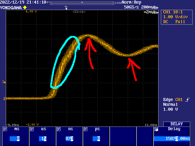
PS: And the duller orange band behind the fuzz is an extra mode of capture where it builds on the multi-pass process to record an even longer history. It accumulates consecutive passes over many seconds, probably millions on top of each other.
I've turned the interpolator off and changed the accumulation to colour for this one:
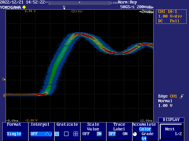
Yes.
Cool. Yeah, sorry, I was thinking in terms of the signal I already understood.
Even without the accumulation mode, at 50 GS/s effective, it must be doing 250 passes (retriggers) of the input signal, at the actual 200 MS/s, to build a single unbroken trace (the bright orange fuzz). So, if there is any non-repeating in the signal for the duration then it'll just make a total mess of the displayed trace.
With accumulation (the dark orange band, or multi-coloured), which can be applied to a single pass trace too, the same effect, of needing a repeating signal, is carried even further.
PS: Each of the 250 passes will have a 20 picosecond delta between each trigger delay timing so as to simulate the 50 GS/s effective sample rate. I have no idea how that is actually achieved.
So for that last trace result @evanh, with your scope you'd be confident the signal contains about 2ns worth of jitter? (about 1 time division)
Yep. I ran one of the older frequencies ...
_clkfreq = 242_726_000The question now is how much jitter with various divd < 22 ?