Using repository mode on the TMDS pins for audio mailboxing works. Just need to add P_REPOSITORY and P_OE to the mode. Though now doing internal capture like @rogloh was doing won't work because repository overrides the IN pins. Hooked it all up to SPCcog (mostly because that one uses a standard 32kHz rate and is very easy to get going without leaving pure ASM land).
So there's that for a test with real audio that won't give you tinnitus. Also attached is a 32kHz version of the test tone program and a first version of the canned packet generator script.
Next step is to figure out resampling (to get the Yamaha 50-something rates straightened out to 48kHz). Concerns over the actual algorithm and increased poll rates aside, I feel like there's a bit of a rounding error problem when trying to resample from one exact CLKFREQ / N rate to another exact CLKFREQ/N rate without introducing any drift. At least using the sort of phase accumulation thing I was thinking of doing. Or maybe not. Need to think it through.
But now you got me thinking I should have made my latest boards with HDMI instead of VGA
Wouldn't need MAX4411 audio amp and probably wouldn't need the LDOs for smooth analog either...
Still, I guess can't do 1080p with this HDMI output...
Although, wait, you can do 1080p at 10 frames/sec if using DLP projector. Edge case though...
@Rayman said:
VGA resolution is good enough for MegaYume and NeoYume, right? Think that's true...
Actually, VGA is insufficent. Because the P2 needs to be clocked higher and the TMDS clock is locked to that, the resolution needs to be increased somewhere. In the emulators, I actually generate an 800x480 signal (that also sorts out that issue where the picture gets stretched out to widescreen) but still need a larger-than-usual HBlank period. This seems to work well enough. Also as mentioned in the other thread, DVI/HDMI output was broken when I added LCD support, just fixed it recently, so if you've tried it in the past and it didn't work, try again.
@Wuerfel_21 said:
Using repository mode on the TMDS pins for audio mailboxing works. Just need to add P_REPOSITORY and P_OE to the mode.
That's awesome. You'll have a handy/quick place to output the samples now from an audio or mixer COG.
A bit later on when I fully wake up I'll try another HDMI device to see if I get better results. Marantz SR5003 home theatre amp which accepts HDMI 1.3. Although I'm sort of imagining it might be fussy too. Will be interesting to see which brands of devices work and which don't with your code if it turns out to be taking any shortcuts.
EDIT: Nope. Didn't work. Says signal not supported and has dashes next to H & V kHz and Hz readings for the input status. Fussy thing. Maybe this is not exactly 50 or 60Hz or has some other timing/format problem. Being a home theater setup it might only need to support the main broadcast formats, unlike an actual monitor which has to be more general purpose (and probably forgiving on the formats accepted).
Feeding the signal directly into the attached projector did display the Reimu thing in normal colours but with no sound obviously as it is a video only device without speakers. So looks like the Marantz receiver won't pass the signal through if it is not happy with it for some reason.
No wonder with these device limitations I couldn't really get anywhere with the HDMI audio thing, even though my FPGA P1V did work at 32kHz on my TV. It must send the right parameters to configure the TV appropriately. I wonder if it is clock sync related as the audio clock can be recovered using a PLL approach with the clock regen packets suitable timestamped rather than just sourced locally (async to source material) which is probably what cheaper devices do and just throw away occasional samples or repeat them if needed.
I'm potentially in the market soon for a new HDMI monitor in my main office setup so hopefully will be able to use that at some point to see if I can get audio going again. All my current devices are just DVI.
Oh yeah, you wouldn't think the signal integrity on that would be great at all... I'm using the EVAL for this testing, mostly because it doesn't do the annoying thing where you have to keep a terminal connection open to stop it from turning off. But putting the breakout on one of @Rayman 's boards also works, as it were.
I think I'm currently using P_LOW_1K5|P_HIGH_1K5 drive mode. I've also seen P_DAC_124R_3V|P_BITDAC|($F7<<8) and P_DAC_124R_3V|P_BITDAC|($FE<<8). Anyone remember which one of these is best? (one of these may be a typo)
In other news, been doing some resampling reseach... Looking at these silly graphs until 5 AM. This would be 6 point sinc with hamming window, which should be in the realm of things the P2 can do in real-time while doing all the other stuff it needs to do:
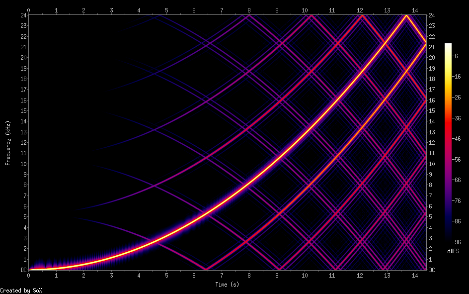
For comparsion, simple linear interpolation does this:
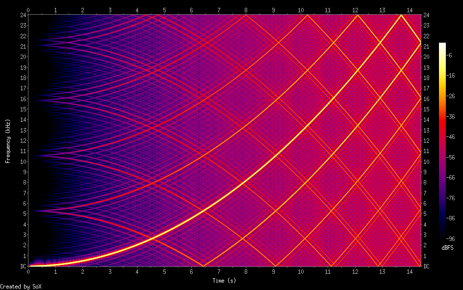
And just skipping samples gives you this:
All of this is still in double-precision lala land though. Not sure if there's any sillyness when actually computing this in fixed-point (esp. around sinc(0)).
I hate this burden of knowledge... Someone else would probably have thrown in the linear interpolation and never worried about it.
@Rayman said:
I'd go linear interpolation for sure. Can you really hear the difference?
Yes. Anytime there's a frequency sweep you can hear the aliasing move around in a way that's harmonically disconnected from the actual tone. This can happens with heavy vibrato effect.
Just looked at Audacity see if had different options for changing sample rate, but doesn't and doesn't say how it does it in the GUI.
It does, it's under "quality" and the default setting for real-time mode has awful passband, increase it.
Believe it or not, I designed a non-terrible filter (8 point now... I know, I keep moving the goalposts) and implement it on P2.
Should still fit in some 300-ish pixel segment of the scanline. Should be able to still fit it with pixel doubling, since it's really mostly CORDIC ops for this sort of thing.
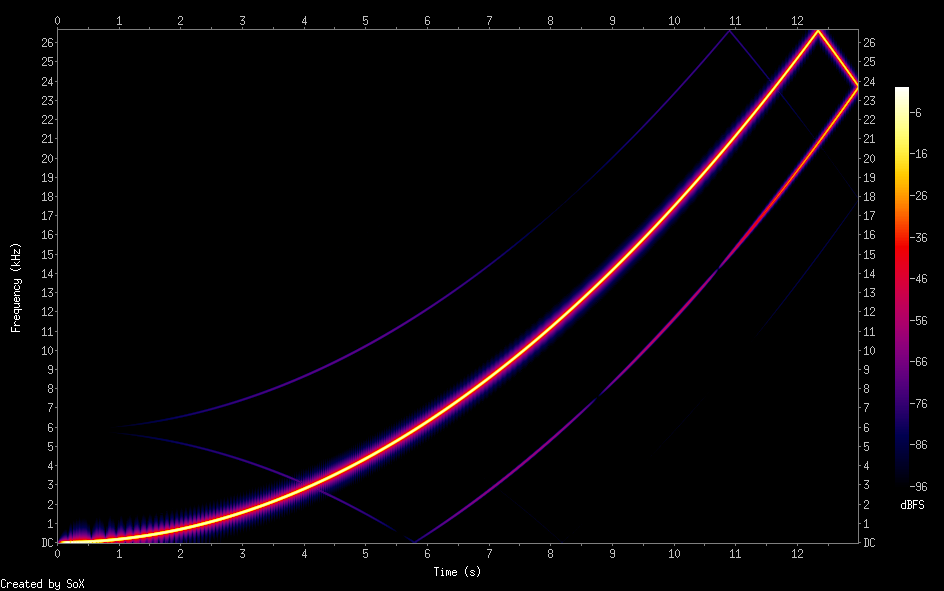
The same filter extended to 32 points (slow!) is really clean, so the idea is right. Here's an animation with that, the 8-point version, the 4 point version and the linear interpolation. (ignore the incorrectly set scales)
(They also sound better, but I'll save you the tinnitus)
So will you re-sync the audio output rate to the video scan line rate? Like 2 or 3 audio samples per scanline or something. Is that the plan? Just wondering how you plan to read these samples from the repo pin at the correct time on the scan line...I think my own intent was to process audio from a small fifo in a group IIRC and send one or two samples out per island as needed. But I quite like the repository pin concept if it simplifies and reduces need for other cogs, and it may be a good way to deal with multi-channel audio too (8 channels) if that eventuates one day.
@rogloh said:
So will you re-sync the audio output rate to the video scan line rate? Like 2 or 3 audio samples per scanline or something. Is that the plan? Just wondering how you plan to read these samples from the repo pin at the correct time on the scan line...I think my own intent was to process audio from a small fifo in a group IIRC and send one or two samples out per island as needed. But I quite like the repository pin concept if it simplifies and reduces need for other cogs, and it may be a good way to deal with multi-channel audio too (8 channels) if that eventuates one day.
The idea is this:
- audio cog generates samples every N cycles as normal, but posts it into the repository pin
- the video cog frequently polls the repository for new samples and adds them to a queue. This just has to happen often enough that it doesn't skip a sample
- when generating an audio packet, the samples are removed from the queue (Resampling will insert here. This will then sometimes consume more than one input sample at a time.)
This is how the SPCcog example works. The good part here really is that the device on the other end of the cable has to deal with making the samples come out in time again.
Also as mentioned, you only ever need to generate scanlines with 1 or 2 samples in them, assuming normal audio rates (32, 44.1 or 48) VGA scan rate ~31kHz. The ratios all come out to 1.xx . Combination of poll intervals might be such that you'd end up with 3 samples in the queue, but you can leave one in, because the next line you'll get at most one more and will be able to clear the queue by flushing out those two samples.
Also also, currently only one repository pin is used with L and R samples packed inside. This is generally easier to deal with and the use case for more than 16 bits seems dubious here (the resampling version will be somewhat limited by MULS being 16-bit, as it were)
Ok I guess that scheme should have legs. I still sort of wonder if you go with the repo pin concept whether you should plan for allowing 20-24 bits samples somewhere down the track (using two pins per stereo source with one pin always written last by convention which signifies the data for both sources is ready, or is just the mono channel) and you just throw away any LSBs internally, because as you say that complicates the interpolation with 16 bit MULS. That way the audio COGs feeding it would just send whatever they do in a left bit justified format and the audio data receiver COG (which may be other code one day) just sends out whatever bits it can support to the final device. That could allow multi-channel high quality HDMI-audio one day from the same audio source COGs without ever rewriting them for example. Go with what you think makes sense for now. You're potentially setting up a P2 audio standard to some degree here, but it can definitely evolve as well. It's early days.
@Wuerfel_21 said:
The idea is this:
- audio cog generates samples every N cycles as normal, but posts it into the repository pin
- the video cog frequently polls the repository for new samples and adds them to a queue. This just has to happen often enough that it doesn't skip a sample
- when generating an audio packet, the samples are removed from the queue (Resampling will insert here. This will then sometimes consume more than one input sample at a time.)
This is how the SPCcog example works. The good part here really is that the device on the other end of the cable has to deal with making the samples come out in time again.
Also as mentioned, you only ever need to generate scanlines with 1 or 2 samples in them, assuming normal audio rates (32, 44.1 or 48) VGA scan rate ~31kHz.
If the audio cog is outputting samples at 32/44.1/48 kHz why is there any resampling? The HDMI sink adjusts to these frequencies, as you say.
@TonyB_ said:
If the audio cog is outputting samples at 32/44.1/48 kHz why is there any resampling? The HDMI sink adjusts to these frequencies, as you say.
Where does it say there is? Read and understand the text before asking silly questions. The resampling is for cases where the frequency is non-standard.
@Rayman said:
So, I guess playing a .wav file from uSD over HDMI at a usual sample rate would be easy for you to implement at this point?
Yes. Can just do that. Could even read the samples from a buffer directly in the video cog, so no other cog is required. You can try that at home (start with the test tone program and keep the HDMI spec on hand)
Something interesting I just noticed: none of the 32kHz test files actually indicate 32kHz in the channel status word. I left it at 44.1kHz. Seems it doesn't matter?
Was wondering if one could just use up some smart pins to do sample rate conversion...
Have one pin output at say 55 kHz with DAC and another pin do say 32 kHz ADC.
Might even be able to do both with one pin, if I'm seeing it right...


Comments
@Rayman These all have working sound?
Yes
My screen was a LG 27UP850 with sound
Using repository mode on the TMDS pins for audio mailboxing works. Just need to add P_REPOSITORY and P_OE to the mode. Though now doing internal capture like @rogloh was doing won't work because repository overrides the IN pins. Hooked it all up to SPCcog (mostly because that one uses a standard 32kHz rate and is very easy to get going without leaving pure ASM land).
So there's that for a test with real audio that won't give you tinnitus. Also attached is a 32kHz version of the test tone program and a first version of the canned packet generator script.
spctest works on my FireTV. Looks like you figured it out! Congrats.
Cool!
Next step is to figure out resampling (to get the Yamaha 50-something rates straightened out to 48kHz). Concerns over the actual algorithm and increased poll rates aside, I feel like there's a bit of a rounding error problem when trying to resample from one exact CLKFREQ / N rate to another exact CLKFREQ/N rate without introducing any drift. At least using the sort of phase accumulation thing I was thinking of doing. Or maybe not. Need to think it through.
But now you got me thinking I should have made my latest boards with HDMI instead of VGA
Wouldn't need MAX4411 audio amp and probably wouldn't need the LDOs for smooth analog either...
Still, I guess can't do 1080p with this HDMI output...
Although, wait, you can do 1080p at 10 frames/sec if using DLP projector. Edge case though...
VGA resolution is good enough for MegaYume and NeoYume, right? Think that's true...
Actually, VGA is insufficent. Because the P2 needs to be clocked higher and the TMDS clock is locked to that, the resolution needs to be increased somewhere. In the emulators, I actually generate an 800x480 signal (that also sorts out that issue where the picture gets stretched out to widescreen) but still need a larger-than-usual HBlank period. This seems to work well enough. Also as mentioned in the other thread, DVI/HDMI output was broken when I added LCD support, just fixed it recently, so if you've tried it in the past and it didn't work, try again.
That's awesome. You'll have a handy/quick place to output the samples now from an audio or mixer COG.
A bit later on when I fully wake up I'll try another HDMI device to see if I get better results. Marantz SR5003 home theatre amp which accepts HDMI 1.3. Although I'm sort of imagining it might be fussy too. Will be interesting to see which brands of devices work and which don't with your code if it turns out to be taking any shortcuts.
EDIT: Nope. Didn't work. Says signal not supported and has dashes next to H & V kHz and Hz readings for the input status. Fussy thing. Maybe this is not exactly 50 or 60Hz or has some other timing/format problem. Being a home theater setup it might only need to support the main broadcast formats, unlike an actual monitor which has to be more general purpose (and probably forgiving on the formats accepted).
Feeding the signal directly into the attached projector did display the Reimu thing in normal colours but with no sound obviously as it is a video only device without speakers. So looks like the Marantz receiver won't pass the signal through if it is not happy with it for some reason.
No wonder with these device limitations I couldn't really get anywhere with the HDMI audio thing, even though my FPGA P1V did work at 32kHz on my TV. It must send the right parameters to configure the TV appropriately. I wonder if it is clock sync related as the audio clock can be recovered using a PLL approach with the clock regen packets suitable timestamped rather than just sourced locally (async to source material) which is probably what cheaper devices do and just throw away occasional samples or repeat them if needed.
I'm potentially in the market soon for a new HDMI monitor in my main office setup so hopefully will be able to use that at some point to see if I can get audio going again. All my current devices are just DVI.
Working perfect spctest and sound32
I am on Jon Mcphalen breadboard and edge revA + parallax HDMI breakout.
Amazing, basepin 32 is on the opposite side of the edge.
Oh yeah, you wouldn't think the signal integrity on that would be great at all... I'm using the EVAL for this testing, mostly because it doesn't do the annoying thing where you have to keep a terminal connection open to stop it from turning off. But putting the breakout on one of @Rayman 's boards also works, as it were.
I think I'm currently using
P_LOW_1K5|P_HIGH_1K5drive mode. I've also seenP_DAC_124R_3V|P_BITDAC|($F7<<8)andP_DAC_124R_3V|P_BITDAC|($FE<<8). Anyone remember which one of these is best? (one of these may be a typo)In other news, been doing some resampling reseach... Looking at these silly graphs until 5 AM. This would be 6 point sinc with hamming window, which should be in the realm of things the P2 can do in real-time while doing all the other stuff it needs to do:
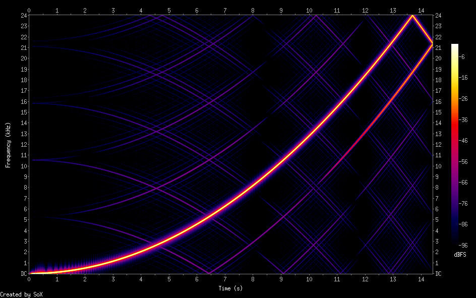
For comparsion, simple linear interpolation does this:
And just skipping samples gives you this:
All of this is still in double-precision lala land though. Not sure if there's any sillyness when actually computing this in fixed-point (esp. around sinc(0)).
I hate this burden of knowledge... Someone else would probably have thrown in the linear interpolation and never worried about it.
Think I fixed above issue with 75 k pull-up resistor on new version , will send you one of those soon…
I guess one could think about doing fft on it and then reverse fft in different sample spacing…
I’m not an audiofile though so I think simplest approach would work for me…
This one on GitHub looks good:
https://github.com/zephray/SampleRateConverter
Floating point though…
I'd go linear interpolation for sure. Can you really hear the difference?
Just looked at Audacity see if had different options for changing sample rate, but doesn't and doesn't say how it does it in the GUI.
Yes. Anytime there's a frequency sweep you can hear the aliasing move around in a way that's harmonically disconnected from the actual tone. This can happens with heavy vibrato effect.
It does, it's under "quality" and the default setting for real-time mode has awful passband, increase it.
Believe it or not, I designed a non-terrible filter (8 point now... I know, I keep moving the goalposts) and implement it on P2.
Should still fit in some 300-ish pixel segment of the scanline. Should be able to still fit it with pixel doubling, since it's really mostly CORDIC ops for this sort of thing.
The same filter extended to 32 points (slow!) is really clean, so the idea is right. Here's an animation with that, the 8-point version, the 4 point version and the linear interpolation. (ignore the incorrectly set scales)

(They also sound better, but I'll save you the tinnitus)
So will you re-sync the audio output rate to the video scan line rate? Like 2 or 3 audio samples per scanline or something. Is that the plan? Just wondering how you plan to read these samples from the repo pin at the correct time on the scan line...I think my own intent was to process audio from a small fifo in a group IIRC and send one or two samples out per island as needed. But I quite like the repository pin concept if it simplifies and reduces need for other cogs, and it may be a good way to deal with multi-channel audio too (8 channels) if that eventuates one day.
The idea is this:
- audio cog generates samples every N cycles as normal, but posts it into the repository pin
- the video cog frequently polls the repository for new samples and adds them to a queue. This just has to happen often enough that it doesn't skip a sample
- when generating an audio packet, the samples are removed from the queue (Resampling will insert here. This will then sometimes consume more than one input sample at a time.)
This is how the SPCcog example works. The good part here really is that the device on the other end of the cable has to deal with making the samples come out in time again.
Also as mentioned, you only ever need to generate scanlines with 1 or 2 samples in them, assuming normal audio rates (32, 44.1 or 48) VGA scan rate ~31kHz. The ratios all come out to 1.xx . Combination of poll intervals might be such that you'd end up with 3 samples in the queue, but you can leave one in, because the next line you'll get at most one more and will be able to clear the queue by flushing out those two samples.
Also also, currently only one repository pin is used with L and R samples packed inside. This is generally easier to deal with and the use case for more than 16 bits seems dubious here (the resampling version will be somewhat limited by MULS being 16-bit, as it were)
Ok I guess that scheme should have legs. I still sort of wonder if you go with the repo pin concept whether you should plan for allowing 20-24 bits samples somewhere down the track (using two pins per stereo source with one pin always written last by convention which signifies the data for both sources is ready, or is just the mono channel) and you just throw away any LSBs internally, because as you say that complicates the interpolation with 16 bit MULS. That way the audio COGs feeding it would just send whatever they do in a left bit justified format and the audio data receiver COG (which may be other code one day) just sends out whatever bits it can support to the final device. That could allow multi-channel high quality HDMI-audio one day from the same audio source COGs without ever rewriting them for example. Go with what you think makes sense for now. You're potentially setting up a P2 audio standard to some degree here, but it can definitely evolve as well. It's early days.
If the audio cog is outputting samples at 32/44.1/48 kHz why is there any resampling? The HDMI sink adjusts to these frequencies, as you say.
Where does it say there is? Read and understand the text before asking silly questions. The resampling is for cases where the frequency is non-standard.
So, I guess playing a .wav file from uSD over HDMI at a usual sample rate would be easy for you to implement at this point?
Yes. Can just do that. Could even read the samples from a buffer directly in the video cog, so no other cog is required. You can try that at home (start with the test tone program and keep the HDMI spec on hand)
This sinc resampling may be useful for my Retromachine Basic "audio nonsense", where I have a problem simlar to this:
while generating "real" (and not synthesized from several harmonics) sawtooth or square wave. To be tested.
@pik33
You probably want something more like the BLIT oscillator from here: https://forums.parallax.com/discussion/175156/anti-aliased-square-wave-synthesis-demo-blit
Same sampling theory and sinc function nonsense at the core of it though.
Something interesting I just noticed: none of the 32kHz test files actually indicate 32kHz in the channel status word. I left it at 44.1kHz. Seems it doesn't matter?
Was wondering if one could just use up some smart pins to do sample rate conversion...
Have one pin output at say 55 kHz with DAC and another pin do say 32 kHz ADC.
Might even be able to do both with one pin, if I'm seeing it right...