@knivd said:
Not yet. I am just about to complete a PCB which uses this module in a practical application, and will report the achieved performance then.
In any case, I do not have the resource nor the time to handle manufacturing, sales and logistics, so it is unlikely I will do this myself. If someone else is interested in taking over to make this reach the market, I will happily supply the sources and whatever other help I can. This is a serious invitation
Any possibility of getting hold of bare boards? If so what price on them? I would like to try building up a couple of these. Of course, the boards would be as is/where is, if I goof one up, so sad too bad, just have to buy another. It looks like a very clean P2 compute module with minimal stuff in the way of whatever one wants to apply it to. Here is the core, just add ideas, software and periph.
If you don't make / distribute these boards. would you consider releasing an archive of the project that could be used to generate one of these boards; Schematics, PCB files or gerbers and maybe BOM either for a fee or perhaps a charitible donation somewhere?
@knivd said:
In any case, I do not have the resource nor the time to handle manufacturing, sales and logistics, so it is unlikely I will do this myself. If someone else is interested in taking over to make this reach the market, I will happily supply the sources and whatever other help I can. This is a serious invitation
I also don't have any resources left over at the moment to handle logistics and sales. But I do have a stencil printer, a P&P machine and a reflow oven. So if somebody else buys the parts and orders the PCBs I could offer to assemble and solder the boards.
The problem I see is that the boards are very small and some components are too close to the edges. So the boards could not be processed by the P&P machine as single pieces. Instead we have to make panels of at least 2x2 "stamps" with a border ring, fiducials and holding tabs so the boards can be separated after soldering.
Okay, here is the thing. I just released the gerber files and the entire manufacturing pack on Github: https://github.com/knivd/P2-STAMP
If someone wants to voluntarily support my work, I created a Patreon page for that (well, since this is my first attempt, I hope I have created it... ): https://www.patreon.com/posts/77640430
If someone wants the Altium source files, I am happy to discuss that too.
Unfortunately, I don't have bare PCBs which I can share. I thought the factory had sent a few, but can't find them now. Might be wrong about that too. If I get any further luck with those, will write separately.
Looking at parts selection choices this board will be a rather expensive one to produce and make QA inspections and not that easy at all. I'd really like to be badly mistaken here.
Beautiful module, btw.
@knivd I really like that you've brought out the ON(RUN) and 3.3V and 1.8V signals out to the external PLCC pins. This will potentially allow your P2 module to be put into a low powered mode, with another external power supply/battery/supercap etc feeding low voltage and low current power into the P2 if it is in this "sleep" state with the P2 operating using the low frequency internal RC oscillator and ready to fully wake up at any time (eg. via the RTC int output or other sensors, assuming it can influence the ON pin from the P2). The LTM regulator disables both its MOSFETs when sleeping so I think this should be possible without draining inside the regulator and the regulator itself only draws a max of 45uA in this state. The flash and HyperRAM when deselected hopefully won't add too much more on top of that and in some separate testing @Tubular already found the P2 can survive with really low currents at lower voltages. So this probably opens things up to some low powered applications for your module. Nice.
@rogloh said:
@knivd I really like that you've brought out the ON(RUN) and 3.3V and 1.8V signals out to the external PLCC pins. This will potentially allow your P2 module to be put into a low powered mode, with another external power supply/battery/supercap .....
I always design with a view for low power usage. This, combined with reduced size places the module squarely in the nice of robotics and mobile automation. P2 is perfectly suited for that.
Of course it is not a $5 thing, but in the end I think most people have already started to realise that the age of massively under-priced electronics which we saw in the past 15-20 years is coming to an end
@knivd said:
...
Of course it is not a $5 thing, but in the end I think most people have already started to realise that the age of massively under-priced electronics which we saw in the past 15-20 years is coming to an end
Hopefully you are right. Designing quality hardware is a serious and very demanding skill and a meticulous process. One starts to realize that once one tries to do such a thing for real. Quality comes at a price, especially when quantity is not helping with bringing the costs down.
I hope this module gets produced eventually and I'll be able to get a few of these too.
Amen to that. Economies of scale has really been amplified by globalism, so that you can get quality hardware at a really cheap price, but with the Chinese manufacturers, as Parallax and others have experienced, they take your meticulous quality design and cheapen it while not even notifying you that what you ordered wasn't actually what they delivered, so every batch has to be inspected for changes.
Sorry for the delayed reaction on this one. If you can compile your source for the P2-STAMP module and post the file for me to upload in it, I am happy to try it at any time. My software knowledge for the P2 is not at such level yet to let me do that myself
Sorry for the delayed reaction on this one. If you can compile your source for the P2-STAMP module and post the file for me to upload in it, I am happy to try it at any time. My software knowledge for the P2 is not at such level yet to let me do that myself
If you tell me what pins you need your video, audio and USB on, I can try, but you kinda need to trail-and-error with the external RAM latency tuning on a new board design, it's kinda fiddly.
The way you build the thing is fairly easy:
- Clone the repository (I just made a fix to allow using HyperRAM without the reset connected (hopefully it works))
- Edit the config.spin2 to your needs. The default is VGA on pins 32..35, audio on pins 30 and 31, USB on pins 16..19. For your HyperRAM the memory section would need to be:
`
' Enable one of these to select the exmem type to use
'#define USE_PSRAM16
'#define USE_PSRAM8
'#define USE_PSRAM4
#define USE_HYPER

' For HyperRAM
HYPER_CLK    =  47
HYPER_RWDS   = 56
HYPER_SELECT = 48
HYPER_BASE   =  48
HYPER_RESET  = -1

HYPER_WAIT  = 22
HYPER_DELAY = 13 ' Play with this value
HYPER_SYNC_CLOCK = false ' This one too
HYPER_SYNC_DATA = false ' This one also
Your DELAY probably needs to be lower. SYNC_DATA is like a half-step for DELAY. The two programs use different clocks and thus might need a different tuning.
Run the build.sh script in a bash shell. If you don't have one on Windows, you can try renaming it to build.bat and just run it through cmd.
Load resulting neoyume_lower.binary or megayume_lower.binary
Pins 32...39 would be perfect as they are currently unused in my application board and I will be able test any function on them without affecting other things
to move the USB pins to 32..35. If you don't actually want to hook anything up, you can enable DIRECT_BOOT to skip the menu selection.
Here's two binaries for megayume with the above settings, one that should bring up the menu and one that direct boots a MEGAUME/AEPD.BIN from the SD card (also provided). If get a magenta screen from the latter, that probably means the memory latency needs tweaking.
Thanks! Loaded fine with loadp2. I can see on the scope that there is definitely activity on the video output pin. Will find some some cable now to put it on screen
The second one shows a distinct "WTF?" message. The file is on the SD (64Gb). I will try to find a smaller card
The "WTF?" message should probably be improved. It means "File not found" (or rather, "file is neither directory nor regular file" according to stat). When using the menu, it shouldn't ever appear (since you can't select a file that doesn't exist), but I guess it appears for direct boot.
Any size card should work, but it needs to be formatted as FAT32 (cards larger than 32GB are factory formatted with exFAT instead). Also, the file needs to be in a MEGAYUME subdirectory, not the root of the card.
I tried them all. Looks like the async files make it happier, and an image started appearing from d9 onward. Something like "Loading ROM...", and then immediately the screen becomes full magenta
The hyper RAM on the stamp module is different from the one used on the Parallax' board, so probably some adjustments there might be needed...
Yes, all produce an initial loading screen briefly and magenta afterwards. There is variation of the magenta colours, though. D13 async produces magenta which then changes to red, and d11 async leads to a darker magenta
Okay, datasheets indicate that your Winbond HyperRAM defaults to 7 latency clocks and the ISSI one parallax uses defaults to 6. There's a register that configures this, but roger's init code doesn't seem to have that ability. Now going to brain hurt about how to properly change the values to account for 7 latency (there's also a place where the 6 latency is hardcoded, I think).
Okay, here's some with 7 latency clocks (I think/hope. The way they are counted makes my brain hurt. I think latency*4 - 2 is the correct value of wait periods after the command phase? That would at least come out right for the previously used value of 22)


Comments
Any possibility of getting hold of bare boards? If so what price on them? I would like to try building up a couple of these. Of course, the boards would be as is/where is, if I goof one up, so sad too bad, just have to buy another. It looks like a very clean P2 compute module with minimal stuff in the way of whatever one wants to apply it to. Here is the core, just add ideas, software and periph.
If you don't make / distribute these boards. would you consider releasing an archive of the project that could be used to generate one of these boards; Schematics, PCB files or gerbers and maybe BOM either for a fee or perhaps a charitible donation somewhere?
I'd PM but others might have input; what will it require to make this thing happen?
I also don't have any resources left over at the moment to handle logistics and sales. But I do have a stencil printer, a P&P machine and a reflow oven. So if somebody else buys the parts and orders the PCBs I could offer to assemble and solder the boards.
The problem I see is that the boards are very small and some components are too close to the edges. So the boards could not be processed by the P&P machine as single pieces. Instead we have to make panels of at least 2x2 "stamps" with a border ring, fiducials and holding tabs so the boards can be separated after soldering.
Okay, here is the thing. I just released the gerber files and the entire manufacturing pack on Github: https://github.com/knivd/P2-STAMP ): https://www.patreon.com/posts/77640430
If someone wants to voluntarily support my work, I created a Patreon page for that (well, since this is my first attempt, I hope I have created it...
If someone wants the Altium source files, I am happy to discuss that too.
Unfortunately, I don't have bare PCBs which I can share. I thought the factory had sent a few, but can't find them now. Might be wrong about that too. If I get any further luck with those, will write separately.
Looking at parts selection choices this board will be a rather expensive one to produce and make QA inspections and not that easy at all. I'd really like to be badly") mistaken here.
mistaken here.
Beautiful module, btw.
@knivd I really like that you've brought out the ON(RUN) and 3.3V and 1.8V signals out to the external PLCC pins. This will potentially allow your P2 module to be put into a low powered mode, with another external power supply/battery/supercap etc feeding low voltage and low current power into the P2 if it is in this "sleep" state with the P2 operating using the low frequency internal RC oscillator and ready to fully wake up at any time (eg. via the RTC int output or other sensors, assuming it can influence the ON pin from the P2). The LTM regulator disables both its MOSFETs when sleeping so I think this should be possible without draining inside the regulator and the regulator itself only draws a max of 45uA in this state. The flash and HyperRAM when deselected hopefully won't add too much more on top of that and in some separate testing @Tubular already found the P2 can survive with really low currents at lower voltages. So this probably opens things up to some low powered applications for your module. Nice.
I always design with a view for low power usage. This, combined with reduced size places the module squarely in the nice of robotics and mobile automation. P2 is perfectly suited for that.
Of course it is not a $5 thing, but in the end I think most people have already started to realise that the age of massively under-priced electronics which we saw in the past 15-20 years is coming to an end
Hopefully you are right. Designing quality hardware is a serious and very demanding skill and a meticulous process. One starts to realize that once one tries to do such a thing for real. Quality comes at a price, especially when quantity is not helping with bringing the costs down.
I hope this module gets produced eventually and I'll be able to get a few of these too.
Amen to that. Economies of scale has really been amplified by globalism, so that you can get quality hardware at a really cheap price, but with the Chinese manufacturers, as Parallax and others have experienced, they take your meticulous quality design and cheapen it while not even notifying you that what you ordered wasn't actually what they delivered, so every batch has to be inspected for changes.
Sorry for the delayed reaction on this one. If you can compile your source for the P2-STAMP module and post the file for me to upload in it, I am happy to try it at any time. My software knowledge for the P2 is not at such level yet to let me do that myself
If you tell me what pins you need your video, audio and USB on, I can try, but you kinda need to trail-and-error with the external RAM latency tuning on a new board design, it's kinda fiddly.
The way you build the thing is fairly easy:
- Clone the repository (I just made a fix to allow using HyperRAM without the reset connected (hopefully it works))
- Edit the
config.spin2to your needs. The default is VGA on pins 32..35, audio on pins 30 and 31, USB on pins 16..19. For your HyperRAM the memory section would need to be:`
Your DELAY probably needs to be lower. SYNC_DATA is like a half-step for DELAY. The two programs use different clocks and thus might need a different tuning.
build.shscript in a bash shell. If you don't have one on Windows, you can try renaming it tobuild.batand just run it through cmd.neoyume_lower.binaryormegayume_lower.binaryOne of Roger's delay testers should help.
Pins 32...39 would be perfect as they are currently unused in my application board and I will be able test any function on them without affecting other things
So then you'd probably set something like
and
to get some basic audio and NTSC video and
to move the USB pins to 32..35. If you don't actually want to hook anything up, you can enable DIRECT_BOOT to skip the menu selection.
Here's two binaries for megayume with the above settings, one that should bring up the menu and one that direct boots a
MEGAUME/AEPD.BINfrom the SD card (also provided). If get a magenta screen from the latter, that probably means the memory latency needs tweaking.Trying with both these files... That doesn't seem right, does it?")
Loading pre-built binaries through Propeller Tool has been broken for years now
Either use the loader that comes with FlexProp (loadp2) or enable SD boot and rename the file to
_BOOT_P2.BIX.Thanks! Loaded fine with loadp2. I can see on the scope that there is definitely activity on the video output pin. Will find some some cable now to put it on screen
I thought that got fixed in the latest build? Maybe I dreamt it")
Maybe it has. I haven't upgraded to the latest build and I get the same access violation message when I try.
All looks good so far...
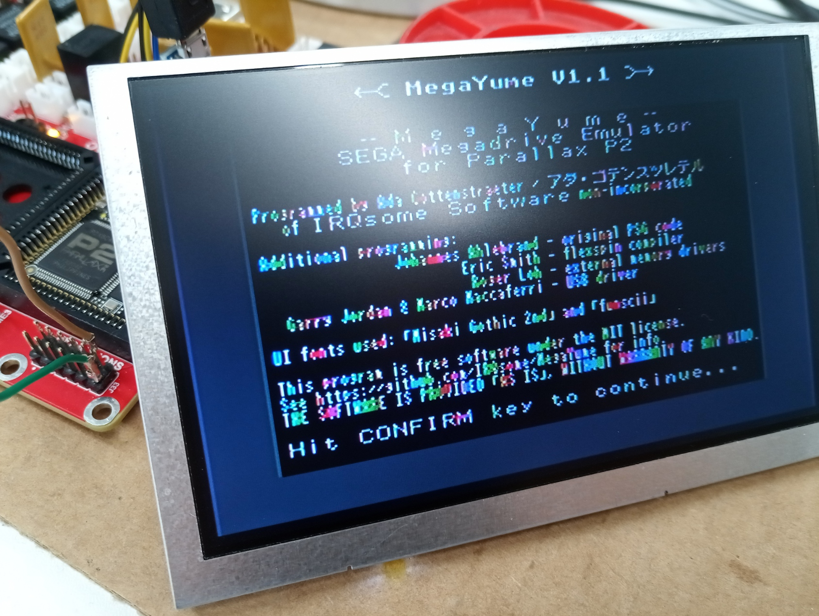
The P2 sits steady at 56.2C degrees (no heatsink)
The second one shows a distinct "WTF?" message. The file is on the SD (64Gb). I will try to find a smaller card
The "WTF?" message should probably be improved. It means "File not found" (or rather, "file is neither directory nor regular file" according to
stat). When using the menu, it shouldn't ever appear (since you can't select a file that doesn't exist), but I guess it appears for direct boot.Any size card should work, but it needs to be formatted as FAT32 (cards larger than 32GB are factory formatted with exFAT instead). Also, the file needs to be in a
MEGAYUMEsubdirectory, not the root of the card.>
Perfect. I formatted it with FAT32, and all went good. But the memory latency will need tweaking (magenta screen)
Just realized I made a typo and RAM select pin is set to 48 instead of 46. Oops.
Okay, here's a bunch of different delay and data sync settings (clock is always async, i don't 100% remember the effect that setting has)
I tried them all. Looks like the async files make it happier, and an image started appearing from d9 onward. Something like "Loading ROM...", and then immediately the screen becomes full magenta
The hyper RAM on the stamp module is different from the one used on the Parallax' board, so probably some adjustments there might be needed...
Yea, maybe there is a difference with the RAM type. Will pour over the datasheets.
Shouldn't all the files come up with the magenta screen? If they don't, something else is popping off.
Yes, all produce an initial loading screen briefly and magenta afterwards. There is variation of the magenta colours, though. D13 async produces magenta which then changes to red, and d11 async leads to a darker magenta
Okay, datasheets indicate that your Winbond HyperRAM defaults to 7 latency clocks and the ISSI one parallax uses defaults to 6. There's a register that configures this, but roger's init code doesn't seem to have that ability. Now going to brain hurt about how to properly change the values to account for 7 latency (there's also a place where the 6 latency is hardcoded, I think).
Okay, here's some with 7 latency clocks (I think/hope. The way they are counted makes my brain hurt. I think latency*4 - 2 is the correct value of wait periods after the command phase? That would at least come out right for the previously used value of 22)
You are a star! It works.
D12 is the sweet spot, both sync and async work, d13 sync also works (but not asyc)