

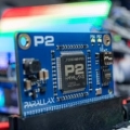
Arlo Power Distribution Board - is this what you asked for?
 Ken Gracey
Posts: 7,420
Ken Gracey
Posts: 7,420
Hey there,
A while back several customers asked for a clean power management system on the Arlo.
One of our forumistas (Phil Pilgrim) designed it quickly for us.
Details are here http://www.parallax.com/news/2014-03-28/arlo-power-distribution-board-arlo-robotic-platform-system-heading-kitting
Please leave us a comment on that page after you take a look.
Ken Gracey
Comments
I'll be wanting two of these when they are available. One for my Arlo, and one to upgrade my older MadeUSA setup.
Seems John Abhsier is happy with the design, too. I can't tell you how much easier this board makes it to wire an Arlo.
We'll be sure to set you up when they're in stock (please remind me).
Ken Gracey
I wish I had one before design the Artist robot .
-Phil
You can copy it and sell it as your own if you wanted to. There are no restrictions on our designs - guess you could say they were open source before it was fashionable. We haven't posted the files but we will in due course.
Ken Gracey
-Phil
The labeling might be a little bit misleading if there's no mention in the documentation. The AUX 12v is battery 12v, not regulated 12v. And the AUX6.5 has a 2amp fuse, along with the 1A 5v fuse, is more than the 2A maximum current rating of the V7806-2000 regulator. So that's something for users to be careful of.
Also, another question: what is the diode for? It doesn't seem like it would help with reverse polarity protection, and if it's being used to drop the battery 12v down than isn't it reducing the overall efficiency of the design, negating some of the switching regulator benefit?
I like the arc design for the screw terminals: that seems like something that would help prevent wires from getting in the way of each other.
Have you considered adding holes for other standard battery connectors? I'm thinking mostly of Deans Plugs and XT60 connectors.
It might also be interesting to make a version that has a buck/boost switching regulator for 12v for systems that require that. You could use the same board and have the regulated 12v be an "upgrade" (since the parts would probably be pretty expensive).
I like the switches and the acrylic cover. That's a nice touch.
Anyway, this board directly addresses one of the most annoying issues in robotics: breaking out the power.
That's a current topic of discussion. After the proto boards arrived, I realized that I could have run the '2940 from the 6.5V fuse, rather than directly from the DC-DC. But, truth be known, the DC-DC is fully short-circuit and overcurrent protected, so the fuse on the 6.5V output is somewhat superfluous anyway. 'Still, it's something that's not too late to change.
The diode is there to isolate the 1000uF cap from back-discharging during transients on the 12V supply and causing 6.5V and 5V brownouts.
No.
You can thank Matt Gilliland, Daniel Harris, and Ken for these features and for the overall concept. I just laid out the board from Matt's DXF drawing showing the board outline and general parts placement.
-Phil
Anyway, probably not as big of an issue with motors that aren't as highly rated as the CIMs, but it's something that caught us all off guard.
You're right! I didn't even notice that the carousel had more images. The arrow blended in with all the noise of the ARLO that was behind it. Perhaps Parallax could make the arrow have a background, and also appear in the popup.
Happy Birthday, Whit!
We found a mistake on the PCB and had to order a second run. Bottom line up front: June 1st, for certain.
Ken Gracey
I actually have a diagram for an Arlo power distribution system on my dry erase board right now which only serves to convince me that I do not really want to build one myself. I've been stalling for months on building an Arlo because of the power distribution system issue.
I think if you can price it just under $100 it will be well worth it to those of us who don't build electronic projects on a routine basis.
The saved time and money in designing the system and then buying all the little pieces and soldering them together is huge. Not to mention the peace of mind knowing some real engineers made the decisions and tested it ahead of me.
Also, it is beautiful. Those of us not good with the drilling and cutting stuff and without laser cutters are very grateful for custom PCBs and acrylic plates!
The Regulator will supply 1 AMP. Should be sufficient for a RPi. You would need to consider other 5 Volt devices also using the same power source.
.
Hi clofland - Welcome to the Forums :-)
The charger isn't on our website yet, but it should be in stock - it's #700-00240. I think it's about $50.
However, you could use any standard 12 SLA battery charger, and if you wanted to use it with this new Power Distribution Board, it would need a center positive 2.5mm x 5.5mm OD jack, to fit into the receptacle.
-MattG
Yep it is kinda cute ;-) - you should see it in real-life!
I'm working on the documentation now and I'll let you know when it's available "RSN".
-MattG