Going from the theory of post #928 to actual coding, here are some of the new routines for performing the job
pub GetXYLegPosition(n):x1, y1 | f1, t1, c1, step1, step2, step3, step4, step5, step6, step7
  'calculate distances using angles in Forward Kinematics
  'return leg cartesian location in x,y,z coordinates
  f1 := 1800 - femurAngle[n]
  t1 := tibiaAngle[n] + femurAngle[n]
  c1 := 1800 - coxaAngle[n]
  debug("Start leg angles ", sdec_(n), ": ", sdec(femurAngle[n]), sdec(tibiaAngle[n]), sdec(coxaAngle[n]))
  debug("Leg XY angle positions: Leg ", sdec_(n), sdec(femurAngle[n]), sdec(tibiaAngle[n]), sdec(coxaAngle[n]))

  'use law of cosines to get triangle side bounded by femur and tibia
  step1 := 426329                                       '(femurlength * femurlength) + (tibialength * tibialength) - values constant
  step2 := 193040                                       '2 * femurlength * tibialength - values constant
  step3 := sqrt(step1-((step2 * qcos(10000,t1,3600))/10000))    'step3 is hypotenous of right triangle
'  debug(sdec(step3))

  ' use law of cosines to get angle for the above triangle
  step4 := (23104 + (step3 * step3)) - 403225           'femurLength*femurLength + step3*step3 - tibialength*tibialength
'  debug(sdec(step4))
  step5 := 2 * femurlength * step3
'  debug(sdec(step5))
  step6 := f1 - (acos((step4*1000) / (step5))/100)      'subtract from femurAngle to get angle at femur pivot point
'  debug(sdec(step6))

  'get base length of right triangle, add coxalength to get X and Y values
  step7 := (step3 * (qsin(10000,step6,3600))/10000) + coxalength
'  debug(sdec(step8))

  'switch to coxa overhead to get x,y values in local leg coordinate system
  x1 := step7 * qcos(10000,c1,3600)/10000
  debug("x: ", sdec_(x1))
  y1 := (step7 * qsin(10000,c1,3600)/10000)
  debug("y: ", sdec_(y1))
  debug("z: ", sdec_(legZactual[n]))
  debug("-----------------------------")
The XYPosition is used during hexapod startup to grab the current X and Y grid positions for each leg tip based on the angle feedback from the individual leg controllers. I had a thought of doing this calculation in the individual leg controllers and instead of feeding the P2 with angle data, send back the X, Y, and Z positions instead. However this requires Floating Point on the P1 to get the trig functions and I don't have any open cogs to run the calculations. So I ended up keeping this calculation on the P2.
The LegIK code was tweaked some to ensure the right angle values were output. The leg controllers base FemurAngle with the leg up being the minimum angle and leg down as maximum. However the Inverse Kinematics is exactly opposite. So 180 degrees minus the femurAngle gets the right orientation for the leg controller. The tibiaAngle output was adjusted to have 0 degrees as the minimum value out of the calculation as the leg can not physically move to a negative tibia angle (changing this would require new parts created, I will live with that limitation for now....)
Leg movements have improved with the changes, however there are times that a leg doesn't move correctly. The debug information shows the P2 is sending the correct leg command. The P2 communicates at a relatively slow 57,600 baud to the leg controllers, so I wonder if the leg controller routine that is looking for the input command is occasionally not getting the command. As an experiment I'll send each movement command out twice and see if that makes a difference.
pub moveLeg(legn, x1, y1, z1, legdwn)
'standard output to move a leg
debug("LegIK input for leg ", sdec_(legn), ": ", sdec(x1), sdec(y1), sdec(z1))
femurAngle[legn], tibiaAngle[legn], coxaAngle[legn] := legIK(x1, y1, z1)
debug("IK output: Leg ", sdec_(legn), ": ", sdec(femurAngle[legn]), sdec(tibiaAngle[legn]), sdec(coxaAngle[legn]))
BuildString(legn, femurAngle[legn], tibiaAngle[legn], coxaAngle[legn], legdwn)
serOut.txStr(@outBuf)
waitms(10)
serOut.txStr(@outBuf)
debug("buildString string output to leg ", sdec_(legn), zstr(@outBuf))
waitms(125)
repeat while checkAllMotorDone(frontleg) == false
waitms(150)
Next part of setting up the tripod gait is developing a process for the step motion. Given the current location of a leg tip, we know the desired leg end point based on the user input of direction and stride length. I can't go directly between the start and end points as each motor affects the leg tip motion differently so the leg could be physically damaged due to too much stress as each motor tries to get to the end point. (don't want the leg tip to 'slide' when on the ground). One way to solve this problem is to break the long distance between the start and end points up into smaller intervals and moving the leg tip between the shorter distances. This gives motors time to finish moving before going to the next location. The legs aren't totally rigid so they can handle a certain amount of movement before the tip wants to slide
The size of each movement is a balance between how fast can the processor figure out the math for the next movement, the resolution of the sensors (affects how small a move can be), and how fast the legs can move. A very small movement gives the least amount of stress to the leg but requires the most computation time and the leg would move fairly slowly. A large movement can stress the leg mechanisms but results in faster movement and minimizes computation time. My initial testing interval will be 10mm of travel along the direction of motion. In other words, take the body stride length and divide it by the interval of 10. This gives the number of individual spots between the start and end points the leg moves to. The leg tips can handle movements slightly greater than 10mm with no issues, any larger a value and then it gets dangerous.
pub bodyIK() | n, temp
' get body movement values and translate to leg positions
' bodyx, bodyy, bodyz are user input values
debug("--------bodyIK----------")
bodyangle := atan2(bodyy,bodyx)/100
bodystride := sqrt((bodyx*bodyx)+(bodyy*bodyy))
debug(sdec(bodystride))
bodystride := 10 * ((bodystride + 9)/10) 'make value divisible by 10 by rounding up, makes for easier math later
gaitIncrement := bodyStride/resolution 'number of movement increments needed from start to end
debug(sdec(bodyy), sdec(bodyx), sdec(bodyangle), sdec(bodystride), sdec(gaitIncrement))
'get current location of each leg and end point for leg movement
coordinateConversion()
setupStepIncrement()
pub coordinateConversion() | n
' convert body movement data to leg coordinates
' debug("--------coordinateConversion----------")
repeat n from 1 to 3
legangle[n] := bodyangle + 900 - fixedlegangle[n]
if legangle[n] > 3600
legangle[n] := legangle[n] - 3600
if legangle[n] > 1800
legangle[n] := legangle[n] - 1800
legangle[n+3] := legangle[n]
repeat n from 1 to 6
' debug("Leg ", sdec_(n), " LegAngle: ", sdec_(legangle[n]), sdec(bodystride), sdec(legXactual[n]), sdec(legYactual[n]), sdec(legZactual))
legXend[n] := ((qcos(10000,legangle[n],3600) * bodystride)/10000) + legXactual[n]
legYend[n] := ((qsin(10000,legangle[n],3600) * bodystride)/10000) + legYactual[n]
' debug("Leg ", sdec_(n), sdec(legangle[n]), sdec(legXend[n]), sdec(legYend[n]), sdec(legZactual[n]))
pub setupStepIncrement()| n
' divide leg movement into discrete steps in the X and Y axis
debug("--------setupStepIncrement)------------")
repeat n from 1 to 6
xIncrement[n] := (qcos(10000,legangle[n],3600)/1000) * resolution
yIncrement[n] := (qsin(10000,legangle[n],3600)/1000) * resolution
debug("Leg ", sdec_(n), ": ", "Angle: ", sdec_(legAngle[n]), sdec(legXStart[n]), sdec(legYStart[n]), ", Xincrement: ", sdec_(xIncrement[n]), ", Yincrement: ", sdec_(yIncrement[n]),sdec(legXend[n]), sdec(legYend[n]))
With that info a step increment value for both the X and Y axis can be determined using sine and cosine. The step increment is added to the current leg X and Y values to get the intermediate movement locations.
pub legIncrementalMove(n, increment)
' move leg in discrete X, Y, Z intervals from start to end point
legXActual[n] := legXStart[n] + (xIncrement[n] * increment)/10
legYActual[n] := legYStart[n] + (yIncrement[n] * increment)/10
debug("Leg ", sdec_(n), ": ", sdec(legXActual[n]), sdec(legYActual[n]))
moveLeg(n, legXActual[n], legYActual[n], legZActual[n], 1)
pub moveLeg(legn, x1, y1, z1, legdwn)
'standard output to move a leg
debug("LegIK input for leg ", sdec_(legn), ": ", sdec(x1), sdec(y1), sdec(z1))
'convert X, Y, Z coordinates to motor angles for the legn
femurAngle[legn], tibiaAngle[legn], coxaAngle[legn] := legIK(x1, y1, z1)
debug("IK output: Leg ", sdec_(legn), ": ", sdec(femurAngle[legn]), sdec(tibiaAngle[legn]), sdec(coxaAngle[legn]))
BuildString(legn, femurAngle[legn], tibiaAngle[legn], coxaAngle[legn], legdwn)
'send movement command to P1 leg controller
serOut.txStr(@outBuf)
waitms(10)
' test - send duplicate movement command since leg controllers occassionally miss the command
serOut.txStr(@outBuf)
debug("buildString string output to leg ", sdec_(legn), zstr(@outBuf))
waitms(125)
'wait while all motors complete movement
repeat while checkAllMotorDone(frontleg) == false
waitms(150)
The legIncrementalMove() is repeated for each leg that needs to move and the increment variable is incremented up to the gaitIncrement value. At that point the leg tip will have moved more or less in a straight line between its starting point and the end point.
This shows the movement steps for just one leg, it becomes multiplied by 6 as each leg is moving. So there is a lot of background computations to be performed. The P1 couldn't keep up with the floating point math so the legs were moving in fits and starts, I never got past being able to move 2 legs simultaneously using the P1. The P2 should be much better plus the code uses integer math now. I need to convert some of the Spin math routines over to in-line PASM2 code (especially LegIK()) but I need to understand the P2 PASM better than I do first.
This is setup work for moving one leg, for the hexapod to move, all 6 legs have to be coordinated by the P2. A tripod gait is planned where at least 3 legs will be down at all time to give a stable platform. 3 legs down move the body in the desired direction while the 3 legs in the air move to a position to implement the next step when they are lowered and the lowered leg group are raised.
I'm considering how to implement the tripod gait, the moveLeg() routine does the IK math and outputs a movement command to a single leg. To handle 6 legs running together I'm thinking of storing the outBuf command string in an array, after all 6 leg commands are figured out, then quickly output the array strings to the leg controllers. This would reduce leg to leg movement delays using a burst vs individual commands. More testing!
With help from the P2 Spin forum I have a solution for storing the P2 movement strings in an array. I’m thinking a solution for helping improve P2 speed is computing all 6 legs at once and storing the movement strings. Once all are complete, send all the movement instructions as a burst to the legs. While the legs are moving into position the next set of computations are completed and ready to send out once the legs complete movement. I also want to re-write the legIK() routine using in-line PASM2 as this is where most of the math is performed.
Next step for me is to put down on paper the expected software flow (this helps keep me on track when coding and is how we used to do software development back when I was coding professionally). Then work on doing the in-line PASM for this critical step. I’ve been putting off learning PASM so now’s a good time to jump in.
But before that I have take my thinking cap off and go find some warm weather for a break from the snow (another 4-6 inches fell last night, just finished shoveling the driveway again….)
I left snow country in Dec 1986 with a snow shovel in the back of my car. I drove until someone asked me what that was for. Then I knew I was in the right place. That was San Diego! I relate to the problem of having to push rain around with a shovel.
Jim
@RS_Jim said:
I left snow country in Dec 1986 with a snow shovel in the back of my car. I drove until someone asked me what that was for. Then I knew I was in the right place. That was San Diego! I relate to the problem of having to push rain around with a shovel.
Jim
One of these days we are going to downsize and move to warmer climates. In the meantime we aren’t ready to give up our toys! The sun came out and the driveway snow is melting in the 30º heat! Just so long as we can make it to the airport in the morning!
Ok, back from a great diving vacation (have to live up to my username!) in Maui and ready to get back to work. I kept up with the various Propellor forums on vacation and found that JonnyMac wrote a nice little bit of inline assembly that takes an x and y vector and returns the angle and length. Since I was doing this in Spin2 in the BodyIK and Leg IK routines the first thing I did was try it out and compare the results from both. The outputs matched and I’m sure the inline PASM is much faster than interpreted Spin.
Had to read through my earlier comments to see where I left off and it seems I said I wanted to do the IK routines in PASM2 for speed. JonnyMac’s contribution is a start, so I will continue to convert them one equation at a time so I can test them properly.
Along with this is coming up with the flow path for updating all 6 leg positions, store the results in an array and then output the array results to each leg. I think this will ensure that the legs stay relatively synchronized as they start their movements all at the same time.
Update time. I’ve been working on learning PASM2 and I’m starting with the LegIK routine. The DEBUG feature is great and helps a lot in figuring out what’s going on. I put a debug command after a SPIN code line to display the output of that line. I run in-line PASM for that line of SPIN code in another pub routine and pass the results back and display them. This helps troubleshooting as I instantly know if the assembly isn’t correct if the 2 debug statements don’t match. Then I research and figure out what I did wrong. This approach is working pretty good, I got to the acos() routine which uses the xypol() command to determine the acos value by passing in a integer value. Unfortunately the first couple of coding rounds haven’t resulted in the expected answer. I tried searching for examples of xypol used in assembly but haven’t found anything (Parallax forum searches are too limited, results are limited and don’t bring back all instances of the search criteria). I’m going to give it another few tries. You would think that having a working SPIN version of acos() that it would be easy to convert to pasm.
Once I get through this hurtle I will do the same PASM conversion of a couple of other math critical routines that are used for calculating leg movements during stepping.
Lots of fun playing and learning PASM2. I took the advice of creating a simplified version of the the SPIN routine used for acos() and complied it using FlexSpin so I could review the .p2asm file. This was very helpful and led to creating 2 inline PASM routines to speed up the LegIK routine which has a lot of trig and runs multiple times (runs every 10mm of leg travel for all 6 legs so it adds up fast) during a stepping motion.
pub law_of_cosine(a, b, c): angle| scale1, t1, t2, t3
' apply law of cosines to input length values where a, b, c are the lengths of the triangle sides
' return angle is angle between a and b sides
' acos based on Flexspin pasm conversion of spin based acos
org
mov scale1, ##1000 'save scaling factor
qmul a, a 'square the a parameter
getqx t1 'a squared result
qmul b, b 'square b param
getqx t2 'b squared result
qmul c, c 'square c param
getqx t3 'c squared result
add t1, t2 'add a2 + b2
sub t1, t3 'subtract c2, save in t1
qmul t1, scale1 'scale value to keep in desired interger value range
getqx t1 'save scaled value to t1
qmul a, #2 'multiply a param by 2
getqx t2 'save result in t2
qmul t2, b 'multiply t2 by b param
getqx t2 'save result in t2
qdiv t1, t2 'divide t1 & t2
getqx t3 'save result in t3 - integer value for acos
_acos1
qmul t3, t3 'square t3
getqx t1 'save to t1
setq #0 'not sure what this does???
qdiv t1, scale1 'divide t1 by scale
getqx t2 'save result in t2
mov t1, scale1 'save scale to t1
sub t1, t2 'subtract t2 from scale value
qmul t1, scale1 'multiply t1 by scale
getqx t1 'save result to t1
cmps t1, #0 wcz 'compare t1 to 0
if_be mov t2, #0 'if t1 = 0, then t2 = 0 - not sure of purpose???
qsqrt t1, #0 'take square root of t1
getqx t2 'save result to t1
qvector t3, t2 'get angle based on adjacent and opposite side of triangle
getqy angle 'get angle value
qmul angle, ##3600 'convert angle value to degrees
getqy angle 'return angle
end
pub _acos(param): angle | scale1, t1, t2, t3
' calculate angle from input integer value
' angle is integer where right digit is 0.1 degree value
' acos based on Flexspin pasm conversion of spin based acos
org
mov scale1, ##1000
qmul param, param
getqx t1
setq #0
qdiv t1, scale1
getqx t2
mov t1, scale1
sub t1, t2
qmul t1, scale1
getqx t1
cmps t1, #0 wcz
if_be mov t3, #0
qsqrt t1, #0
getqx t3
qvector param, t3
getqy t2
qmul t2, ##360000
getqy angle
end
Since I don't know if it is possible to call another inline PASM routine from inside another inline PASM routine, I embedded the acos() section inside the law_of_cosine() PASM.
These work well, they were tested using debug() against the SPIN version to make sure the outputs were matching for each calculation. I'm sure these can be improved upon, I've already gone back over the code several times as I figured out faster/better ways to remove extra steps. There are still a couple of steps that I don't really know what they are doing from converting the Flexspin pasm over. I'll study it some more and see if I can figure it out.
Spent time pushing various values to the new described above PASM2 routines and verifying via a calculator that I was getting the correct values out. Looks great!
Looked through the P2 code to see where else I could use either of these routines and saw the XYLegPosition() uses law of cosines. I started a simple test first just to see the code output before I made any changes. All leg x, y, z positions were showing as 0. A check of the input buffer string values from the leg's P1 processors into the P2 showed the P2 input buffer empty.
Looking just at the input buffer alone I found that the buffer has good data for 102 iterations then it either goes completely empty for the following iterations or has a couple of good values and then goes blank by the 107 iteration.
This led me to examine the P1 leg controller string output to the P2, no issues found there, good data flows continuously on the wire from the P1 to P2.
Back at the P2 I found that the getcmd() routine that actually inputs the P1 values into the input buffer stops seeing the leading char ($) that signals the start of a new string and instead sees the value -1 and quits the routine (which is the correct behavior if it doesn't see the lead char). However it never picks up the $ char again.
pub getcmd(hdr, pstr, len, port): result | i, k, char 'routine designed by Jon McPhalen
' get command from serial stream
' hdr is required header character
' pstr is pointer to string space for command
' len is maximum length of input (buffer len-2)
' port (1-6) selects serial object
repeat
case port
1: char := serL1.rxcheck()
2: char := serL2.rxcheck()
3: char := serL3.rxcheck()
4: char := serL4.rxcheck()
5: char := serL5.rxcheck()
6: char := serL6.rxcheck()
debug(sdec(port), sdec(char))
if char == -1 ----> char no longer sees hdr characther ($), char value = -1)
result := -1
quit
byte[pstr][0] := (k := char) ' get char from stream
if (k == hdr) ' if header
quit
if result == 0
i := 1 ' set starting index
repeat while (i < len)
case port
1: char := serL1.rxcheck()
2: char := serL2.rxcheck()
3: char := serL3.rxcheck()
4: char := serL4.rxcheck()
5: char := serL5.rxcheck()
6: char := serL6.rxcheck()
if char == -1
quit
byte[pstr][i] := (k := char) ' get char from stream
if (k == 8) ' if backspace
idx := --i #> 1 ' backup
elseif ((k == 0) OR (k == 13)) ' if 0 or CR, quit
quit
else
++i ' advance pointer
byte[pstr][i] := 0 ' terminate string
I tried increasing the buffer size, this did not change the point where data stops at 102 iterations from the 6 legs. I saw a similar issue quite a while back but it mysteriously started working right again so I'm at a loss as to what is happening. Ihtink it may have something to do with the multiport serial object I'm using (mpx_fullduplexserial) but I can't see where in that code could just stop reading the data.
I'll have to take a break and think this over some more. The communications code hasn't been touched in months so why this problem has come back is baffling. This is the feedback loop from the legs and is critical for operation as it is the verification that legs have moved to the correct position. Suggestions are welcome.
Still haven't come up with a solution for the data flow issues discussed in the previous posting. To take a break from that troubleshooting I tackled the GetXYPosition() routine again and sent it fixed values instead of actual values (easier troubleshooting with fixed values).
Right off the bat I discovered that I incorrectly applied some geometry to my leg positions which meant the previous 'working' code was throwing out bad values. I found the error and started re-writing the code in SPIN before I try converting it to PASM.
This is where I discovered my next mistake/assumption, coding POLXY() in SPIN. The output numbers weren't matching my manual calculations so did some searches that came up with this thread: https://forums.parallax.com/discussion/173878/qrotate-and-qvector-made-simple. This discussion made me realize my coxa movements were 180 degrees out of synch with what the P2 commands were expecting as angle value 0 is the horizontal line to the right of the Y axis, my setup was opposite. This required some head scratching for a while but I came up with a fairly simple solution that returns the correct X and Y values with the correct signs for the circle quadrant.
pub GetXYLegPosition(n):x1, y1 | f1, t1, c1, c2, step1, step2, step3, step4, step5, step6, step7, step8
'calculate distances using angles in Forward Kinematics
'n - leg number
'return leg cartesian location in x,y coordinates
'using fixed input angle values instead of global values for testing
f1 := 1800 - 701 'femurAngle[n]
t1 := 4 + 701 'tibiaAngle[n] + femurAngle[n]
c2 := 1000
c1 := c2
if c1 > 900
c1 := 1800 - c1 'convert angle to CCW rotation for math
debug("Leg XY angle positions: Leg ", sdec_(n), sdec(f1), sdec(t1), sdec(c1))
'test faster calculations
step1 := t1 'get angle
debug(sdec(step1))
step2 := (femurLength*femurLength) + (tibiaLength*tibiaLength) 'run law of cosines for length of side between femur joint and leg tip
' debug(sdec(step2))
step3 := 2*femurLength*tibiaLength
' debug(sdec(step3))
step4 := abs(qcos(10000,step1,3600))
' debug(sdec(step4))
step5 := (step3 * step4)/10000
' debug(sdec(step5))
step6 := step2 - step5
' debug(sdec(step6))
step7 := sqrt(step6) 'output side length from law of cosines
' debug(sdec(step7))
step8 := sqrt((step7*step7) - (bodyz*bodyz)) ' get right triangle side length
' debug(sdec(step8))
step1 := step8 + coxaLength 'add in coxa length to get total length
' debug(sdec(step1))
step2 := abs(c1 * ($80000000 / 180))
debug("c1 conversion: ", sdec_(step2))
x1, y1 := polxy(step1, step2) 'given total length and angle, return x and y
if c2 < 900 ' this means coxa is in 2nd quadrant, so x is negative
step3 := step3 * -1
debug("Results: ", "Hypot: ", sdec_(step1), " angle: ", sdec_(step2), " x: ", sdec_(x1), " y: ", sdec_(y1))
I have to run some more numbers through this routine but it appears to be good so far. I know it isn't pretty but I broke each math section down for easier checking against manually calculated values. I'll convert this over to PASM mainly for the extra speed and for practicing my PASM coding.
I haven’t posted in a while so here is a quick catchup!
The previous post on the GetXYLegPosition() routine was getting some strange outputs values when I approached some of the leg angle limits. This lead me to discover a mistake I made in geometry which was pushing values out of spec. That was a subtle error and had nothing to do with programming which is where I was spending a lot of time puzzling over until I went back to my geometry drawings where it showed up fairly quickly. Anyway, the math was corrected and I’m getting the expected values even at the extremes of leg travel.
Still having issues with the data communications between the P1 to P2. Each P1 is supposed to to be sending a continuous stream of position data separated by commas back to the P2, each leg has its own independent serial pin on the P2 to talk to. However the stream of data works fine and then just stops after going through a very specific number of iterations. This leads me to think its P2 buffer size related but changing the buffer size doesn’t change the number of position data sent. I want to try another multi-port object and see if it occurs there also, just have to search the forum to see what other ones are available (I could go back and try to finish up my earlier attempt at a multiport object also…)
That’s where I left the robot when we left on our summer travels so everything is on hold until we get back home. But I still read this forum daily, just too much neat stuff going on here!
Just poking my nose in this topic - Some comments on optimisation uses of Cordic. Since it is a co-processor it runs concurrently to the cogs. It is also pipelined for multiple commands at once. This means it can be commanded to execute commands both while the cog is executing other instructions and the Cordic can also execute multiple overlapping commands at once:
@DiverBob said:
pub law_of_cosine(a, b, c): angle| scale1, t1, t2, t3
' apply law of cosines to input length values where a, b, c are the lengths of the triangle sides
' return angle is angle between a and b sides
' acos based on Flexspin pasm conversion of spin based acos
org
mov scale1, ##1000 'save scaling factor
The MOV can be shifted down one instruction so the QMUL starts earlier
qmul a, a 'square the a parameter
getqx t1 'a squared result
The first GETQX can be later to allow the second QMUL to run earlier
qmul b, b 'square b param
The second GETQX can also be later to allow the third QMUL to run earlier
getqx t2 'b squared result
qmul c, c 'square c param
getqx t3 'c squared result
So, if all first three GETQXs were here then the first three QMULs would finish notably earlier. The results come out of the Cordic in the same order as the commands were issued
add t1, t2 'add a2 + b2
sub t1, t3 'subtract c2, save in t1
qmul t1, scale1 'scale value to keep in desired interger value range
getqx t1 'save scaled value to t1
qmul a, #2 'multiply a param by 2
getqx t2 'save result in t2
Same story here, two GETQXs after two QMULs would make it faster
qmul t2, b 'multiply t2 by b param
getqx t2 'save result in t2
qdiv t1, t2 'divide t1 & t2
getqx t3 'save result in t3 - integer value for acos
_acos1
qmul t3, t3 'square t3
getqx t1 'save to t1
setq #0 'not sure what this does???
SETQ #0 is redundant: #0 is default. Q register used only when SETQ instruction precedes QDIV.
qdiv t1, scale1 'divide t1 by scale
getqx t2 'save result in t2
mov t1, scale1 'save scale to t1
sub t1, t2 'subtract t2 from scale value
qmul t1, scale1 'multiply t1 by scale
getqx t1 'save result to t1
cmps t1, #0 wcz 'compare t1 to 0
if_be mov t2, #0 'if t1 = 0, then t2 = 0 - not sure of purpose???
CMPS and MOV don't achieve anything as t2 is overwritten below
qsqrt t1, #0 'take square root of t1
getqx t2 'save result to t1
qvector t3, t2 'get angle based on adjacent and opposite side of triangle
getqy angle 'get angle value
qmul angle, ##3600 'convert angle value to degrees
getqy angle 'return angle
Going further, given the large number of multiples, I'm also guessing there is a lot of small numbers involved. These cases can be sped up further by using MUL instruction in place of the early QMULs.
And I note you've got a comment about scale1 being for limiting the magnitude. This can often be absorbed using muldiv64() with its 64-bit intermediate. Which is where SETQ comes into play ...
EDIT: Here's an untested rewrite. It didn't require any divides in the end:
pub law_of_cosine( a, b, c ) : angle | a2, b2, c2
' apply law of cosines to input length values where a, b, c are the lengths of the triangle sides
' return angle, C, is angle between a and b sides in 10ths of degrees
' Formula: c2 = a2 + b2 - 2ab cos(C)
' => 2ab cos(C) = a2 + b2 - c2
' => cos(C) = (a2 + b2 - c2) / 2ab ... or Cos(x) = adjacent / hypotenuse
' => C = arccos( adjacent / hypotenuse )
org
mov a2, a
mul a2, a2 'square the a parameter
mov b2, b
mul b2, b2 'square the b parameter
mov c2, c
mul c2, c2 'square the c parameter
add a2, b2 'add a2 + b2
sub a2, c2 'subtract c2 => adjacent
mov c2, a
mul c2, b
shl c2, #1 'a times b times 2 => hypotenuse
'However, QVECTOR requires adjacent and opposite rather than hypotenuse
' therefore extract opposite from adjacent and hypotenuse using Pythagoras Theorem: adjacent2 + opposite2 = hypotenuse2
' => b2 = c2 - a2
qmul a2, a2 'square adjacent
qmul c2, c2 'square hypotenuse
getqx angle 'adjacent squared
getqy b2
getqx c2 'hypotenuse squared
sub c2, angle wcz 'b2 = c2 - a2
getqy angle
subx angle, b2
qsqrt c2, angle 'squareroot opposite2
getqx b2 'opposite
qvector a2, b2 'adjacent, opposite
getqy angle '32-bit angle
qmul angle, ##3600 'scale to 10ths of degree
getqy angle
end
Thanks for the information, I’m away from the computer for a while but want to try this out when I get home again! It’s fun playing around with PASM2, just a lot there to digest.
I've also found adjusting the least digit of the final multiply, as above, produces suitable rounding.
EDIT: Oops, I see a syntax typo is present in my source, I've used dots in place of commas for two lines, they caused a compile error in my testing too ... fixed.
@evanh said:
I've also found adjusting the least digit of the final multiply, as above, produces suitable rounding.
QSQRT, like QDIV, rounds down (truncates). Which means it tends to produce a low value for "opposite" which in turn means the angle from QVECTOR is also slightly low. Just detectable in the 4 decimal places update above.
Okay, the rounding error wasn't really the main issue. Rather, it was from the limited resolution of my test numbers. Calculating opposite needs to utilise the full precision of QSQRT to then also fully utilise QVECTOR's precision.
With that in mind, it didn't take long to realised the triangle sides could be automatically scaled to increase resolution because only the angle is needed, everything else gets discarded in the end.
Updated with upscaling of intermediate right-angle sides:
pub law_of_cosines( a, b, c ) : angle | hyp, opp
' apply law of cosines to input length values where a, b, c are the lengths of the triangle sides
' return angle, C, is angle between a and b sides in 10ths of degrees
' Formula: c2 = a2 + b2 - 2ab cos(C)
' => 2ab cos(C) = a2 + b2 - c2
' => cos(C) = (a2 + b2 - c2) / 2ab ... or Cos(x) = adjacent / hypotenuse
org
mov hyp, a
mul hyp, b
shl hyp, #1 ' a * b * 2 => hypotenuse
mul a, a ' square the a parameter
mul b, b ' square the b parameter
mul c, c ' square the c parameter
add a, b ' add a2 + b2
sub a, c ' subtract c2 => adjacent
'However, QVECTOR requires adjacent and opposite rather than hypotenuse
' therefore extract opposite from adjacent and hypotenuse using Pythagoras Theorem: adjacent2 + opposite2 = hypotenuse2
' => b2 = c2 - a2
'using QMUL
encod b, a
encod c, hyp
fge b, c
subr b, #30 wcz ' if highest is below 31 bits then scale to 31 bits
if_a shl a, b
if_a shl hyp, b
qmul hyp, hyp ' square hypotenuse
qmul a, a ' square adjacent
getqx opp ' hypotenuse squared
getqy angle
getqx c ' adjacent squared
getqy b
sub opp, c wcz ' opp2 = hyp2 - adj2
subx angle, b ' upper bits
qsqrt opp, angle ' squareroot opposite2
getqx opp ' opposite
qvector a, opp ' adjacent, opposite
getqy angle ' 32-bit angle
qmul angle, ##360_000001 ' degrees with 6 decimal places
getqy angle
end
@DiverBob said:
The previous post on the GetXYLegPosition() routine was getting some strange outputs values when I approached some of the leg angle limits. This lead me to discover a mistake I made in geometry which was pushing values out of spec. That was a subtle error and had nothing to do with programming which is where I was spending a lot of time puzzling over until I went back to my geometry drawings where it showed up fairly quickly. Anyway, the math was corrected and I’m getting the expected values even at the extremes of leg travel.
We are back from our spring travels so finally got back in the basement and work on reintroducing myself to the code. I spent one day getting back up to speed on where I left off so today was spent going line by line through GetXYLegPosition() and checking all the calculations. Found and fixed a couple of assembly language problems that I hadn't noticed earlier. Got to the point where I use the of cosines to get what is the value for a right triangle hypotenuse length only to realize the output value is too short, one of the leg values is larger, which is a big no-no in geometry. So back to the diagrams and figure out where I messed up the math or geometric identities. The only other option is that some of the rounding of values in the P2 calculations is enough to throw things out.
Hopefully I will have more time to work on the robot over this summer!
Always fun to travel but its nice to be back home with all our ‘toys’!
After laying in bed last night trying to fall asleep, here I am with geometry identities and trig running through my head! One good thing is I realized I had made another bad assumption, so today I was able to test the ‘fix’ and it worked! That allowed me to attack the next issue where the calculated hypotenuse for a right triangle (the angle between the tip of the leg on the ground and the pivot point for the femur). I needed to calculate the distance between the leg tip and the point directly under the femur pivot. I use a fixed value for the height above the ground to the femur pivot since that will be determined by the operator via the radio controller. Turns out the value I plugged in as a constant was for a different set of femur/tibia values and in this case no right triangle could be made with the input values. However the P2 still powers through the calculations, its just the output numbers make no sense! Once I plugged in the correct height, I then got the expected output values.
I still need to clean up the assembly code and since I used QDIV several times there is room for improving the speed of the routine.
Its been a frustrating few days now, just need an opportunity to vent...
After fixing the previous problems, I test the systems by doing some simple leg movements controlled by the P2 program. I select a single leg, manually send a leg movement command string (ex: $,2,900,0,900,1) serially to the designated leg and let it move to the position. This is a simple routine that I have used for quite a while and is totally unrelated to any of the changes I have been dealing with. This verifies the P2 program, the P2 to P1 serial connection, actual leg movement, and then P1 to P2 serial connection. The leg does not responding correctly, the motors are moving in small increments, (leg movement indicates at least something is being transmitted from the P2-P1) but no where near the commanded positions. I plugged into the individual leg controllers and send the same command string via PST and everything works great. I can see the P1 response string that is being sent back to the P2 after the movement so the P2 is being informed of the movement.
It looks like something might be going wrong in the serial communications between the P2 to P1 interface. This has been a source of various problems for a while now and at this point I'm not sure how to proceed. If the feedback from the P1 controllers isn't getting back to the P2 reliably or serial communication from the P2 to the P1 controllers aren't being received properly then there is no way this robot is going to be able to walk.
I think my next step might be to pull out the current communications routines and try out another multi-line serial object for the P2. The P1 serial communications appears to be working correctly when I hook it up to the logic analyzer so focusing on the P2 side of things.
It makes it hard to get motivation to work on the robot when so many things are not working as expected, really want to find someone locally that would like to collaborate on this project. Much more fun to have someone to bounce ideas off of and see other options.
Venting mode is now disabled.
Time to look for another P2 multi-line communications object to try out and see if the results are any different. Will have to dig through the P2 forums and see what is out there. I'm using mpx_mutiportserialdriver right now. Any other suggestions?
Update time
I've been spending several days reading and searching on the various multi-port serial interfaces. I got some good ideas from looking at the code so I decided to revisit my version of a mult-port serial and see if I could get a bit further with it. I had stopped work on it when other options became available and had left it partially working. Getting back into the PASM code and using the DEBUG has identified some of the issues I had and I was able to correct some of them. The goal in my design was to simplify the setup and use a series of memory arrays to hold all the various values needed to operate.
First testing the TX side and although some parts of the PASM code are working, there seems to be a problem with actually sending the value to the selected smartpin. I think my array offsets are the problem so will dive deeper into that next.
@RS_Jim said:
@DiverBob
Haven't seen an update in a long time. Still working on the multiport serial?
Jim
Its been a busy time around the house since we got back from our summer travels and have only spent a few evenings with the robot. I am still troubleshooting the multi-port serial object. That needs to be up and running reliably before I can transition back to programming the master for coordinating leg movements.
It’s not forgotten but assembly language isn’t my area of expertise so it is very slow progress so far making it harder to get motivated when there are other things I also need to do around the house! I’ll see if I can hit it today and maybe post some status on the code. Maybe someone else can see where I’m going wrong
Time for an update, but let’s start with a little history (this has been a long project!)…
The robot has an individual leg controller using a P1 processor for each of the 6 legs. Originally the master computer was going to be another P1 processor. However over time I discovered that the P1 could not perform all the math and other functions fast enough so even a single leg moving was very jerky (to be fair, the math used Floating Point and I used Spin as the programming language so that didn’t help either). Luckily about that time the P2 was getting released for early adopters. I got the first Engineering Sample (I believe it was an “A” version) and got started playing with it. Shortly on it was updated as a ‘B’ or ‘C’ version with additional capabilities.
Pnut and FlexSpin came out (I even dabbled in the Prop C language) and eventually the PropTool was updated for the P2 so there were lots of choices for programming languages. Learning the newer Spin 2 language was fun as well as this new capability of in-line PASM. Unfortunately the P2 didn’t have the wealth of documentation and pre-made code objects the P1 had so progressing was slower than I initially counted on. But I was able to do a lot of conversion of the original P1 master code over to the P2.
One thing that is vital to the project is the ability to serially communicate between the P2 and multiple P1s, and back again. Although there were a few serial communications objects out there, none could handle the number of open serial ports I needed. I started to write my own multi-port serial object but my assembly writing abilities weren’t up to the task. To learn assembly I started writing small packets of in-line PASM for some of the speed critical routines that I had written in SPIN. This definitely improved my PASM skills but those skills were still pretty weak!
Cluso99 wrote the first multi-port serial object that I was able to incorporate into the P2 master. This worked well but I discovered some limitations that meant that the feedback from the P1 controllers was not reliably getting back to the P2. This eventually drove me back into trying to modify JonnyMac’s excellent FullDuplexSerial.spin2 and use it as a basis for a multi-port serial object. I think I had a good concept but it wasn’t turning out quite right. I mentioned this issue during the November monthly Parallax Zoom meeting and Stephen Moraco graciously offered to help out. I sent him a copy of what I had done thus far and today he sent back a working copy for me to test!
So today I am working on putting the new code into the P2 master and seeing how it does. We really have a great community of people out here and I have gotten so many great suggestions for coding and hardware over the years. This robot would not be where it is without everyone’s input.
It's finally time to report on some success!
Stephen Moraco has been working with me and he developed another multiple port communications object for the P2. I incorporated the new code in the P2 master computer and after a few bumps where Stephen was able to explain the error of my ways, I am getting good feedback from the 6 leg controllers. I ran the P1 -> P2 com ports for a couple of hours with no issues seen.
This allows me to go back and figure out where I was before I stopped due to the communications issues, so time to read some of my old entries in here! (another good reason for keeping updates with these long distractions).
I believe I will step back a bit and do some work on getting a single leg to move in a straight line. This will test the speed of the P2 for running the IK calculations. It also can let me know if I am going down the right path in the way I am using IK.
On startup of the robot computers, the 6 leg controllers send the P2 master their current leg position, motor status, motor direction, whether the leg is touching ground. The lack of this information is where I first ran into trouble with the communications as the P2 master has to know where the individual legs are before it can do anything. I have a routine that converts the P1 leg angle data into an x,y grid value and checks if the leg is touching the ground. Since the robot legs are above the ground I can manually touch the leg down sensors and validate the leg registers the ground. All sensors but leg 1 are working, so will troubleshoot and fix this first.
It feels good to be able to move forward again.
Troubleshooting the leg 1 ground touch sensor I found the sensor was working properly. The problem was when I re-coded the RGB lights for the new serial object, I messed up the array so the program was skipping over that light each time. All fixed now so moving on to the next item.
Next step is to make sure the P2 -> P1 communications is in order. This is a single P2 transit port that is wired to all the P1s. The P2 transmits movement requests in the format “$,LegNumber, FemurAngle, TibiaAngle, CoxaAngle, LegDown”. The “$” is the start indicator, “LegNumber” is what the P1’s look for. The motor angles are next, followed by “LegDown” which tells the P1 whether or not to go to the requested position or stop movement once the leg down sensor actuates.


Comments
Going from the theory of post #928 to actual coding, here are some of the new routines for performing the job
pub GetXYLegPosition(n):x1, y1 | f1, t1, c1, step1, step2, step3, step4, step5, step6, step7 'calculate distances using angles in Forward Kinematics 'return leg cartesian location in x,y,z coordinates f1 := 1800 - femurAngle[n] t1 := tibiaAngle[n] + femurAngle[n] c1 := 1800 - coxaAngle[n] debug("Start leg angles ", sdec_(n), ": ", sdec(femurAngle[n]), sdec(tibiaAngle[n]), sdec(coxaAngle[n])) debug("Leg XY angle positions: Leg ", sdec_(n), sdec(femurAngle[n]), sdec(tibiaAngle[n]), sdec(coxaAngle[n])) 'use law of cosines to get triangle side bounded by femur and tibia step1 := 426329 '(femurlength * femurlength) + (tibialength * tibialength) - values constant step2 := 193040 '2 * femurlength * tibialength - values constant step3 := sqrt(step1-((step2 * qcos(10000,t1,3600))/10000)) 'step3 is hypotenous of right triangle ' debug(sdec(step3)) ' use law of cosines to get angle for the above triangle step4 := (23104 + (step3 * step3)) - 403225 'femurLength*femurLength + step3*step3 - tibialength*tibialength ' debug(sdec(step4)) step5 := 2 * femurlength * step3 ' debug(sdec(step5)) step6 := f1 - (acos((step4*1000) / (step5))/100) 'subtract from femurAngle to get angle at femur pivot point ' debug(sdec(step6)) 'get base length of right triangle, add coxalength to get X and Y values step7 := (step3 * (qsin(10000,step6,3600))/10000) + coxalength ' debug(sdec(step8)) 'switch to coxa overhead to get x,y values in local leg coordinate system x1 := step7 * qcos(10000,c1,3600)/10000 debug("x: ", sdec_(x1)) y1 := (step7 * qsin(10000,c1,3600)/10000) debug("y: ", sdec_(y1)) debug("z: ", sdec_(legZactual[n])) debug("-----------------------------")The XYPosition is used during hexapod startup to grab the current X and Y grid positions for each leg tip based on the angle feedback from the individual leg controllers. I had a thought of doing this calculation in the individual leg controllers and instead of feeding the P2 with angle data, send back the X, Y, and Z positions instead. However this requires Floating Point on the P1 to get the trig functions and I don't have any open cogs to run the calculations. So I ended up keeping this calculation on the P2.
pub legIK(x1, y1, z1): femurAngle1, tibiaAngle1, coxaAngle1 | L, L1, c, ikb, ikb1, ikb2, t1, t2, t3
' output leg angle values for leg position inputs
'  debug("---- start legIK ---------")
  L1 := sqrt(x1*x1 + y1*y1)
'  debug(sdec(L1))

  L := L1 - coxalength
'  debug(sdec(L))

  c := sqrt(z1*z1 + L*L)
'  debug(sdec(c))

  t1 := (femurLength*femurLength)+(c*c)-(tibiaLength*tibiaLength)
'  debug(sdec(t1))
  t2 := 2*femurLength*c
'  debug(sdec(t2))
  t3 := (t1 * 1000)/t2
'  debug(sdec(t3))
  ikb := acos(t3)/100
'  debug(sdec(ikb))

  ikb2 := acos(z1 * 1000 / c)/100
'  debug(sdec(ikb2))

  t1 := (tibiaLength*tibiaLength)+(c*c)-(femurLength*femurLength)
'  debug(sdec(t1))
  t2 := 2*tibiaLength*c
'  debug(sdec(t2))
  t3 := (t1 * 1000)/t2
'  debug(sdec(t3))
  ikb1 := acos(t3)/100
'  debug(sdec(ikb1))

  femurAngle1 := 1800-(ikb+ikb2)                                                'convert angle to measure from CW direction vs CCW.
  tibiaAngle1 := ikb2-ikb1 #> 0
  coxaAngle1 := atan2(y1, x1)/100
'  debug("IK output: ", sdec(femurAngle1), sdec(tibiaAngle1), sdec(coxaAngle1))
The LegIK code was tweaked some to ensure the right angle values were output. The leg controllers base FemurAngle with the leg up being the minimum angle and leg down as maximum. However the Inverse Kinematics is exactly opposite. So 180 degrees minus the femurAngle gets the right orientation for the leg controller. The tibiaAngle output was adjusted to have 0 degrees as the minimum value out of the calculation as the leg can not physically move to a negative tibia angle (changing this would require new parts created, I will live with that limitation for now....)
Leg movements have improved with the changes, however there are times that a leg doesn't move correctly. The debug information shows the P2 is sending the correct leg command. The P2 communicates at a relatively slow 57,600 baud to the leg controllers, so I wonder if the leg controller routine that is looking for the input command is occasionally not getting the command. As an experiment I'll send each movement command out twice and see if that makes a difference.
pub moveLeg(legn, x1, y1, z1, legdwn) 'standard output to move a leg debug("LegIK input for leg ", sdec_(legn), ": ", sdec(x1), sdec(y1), sdec(z1)) femurAngle[legn], tibiaAngle[legn], coxaAngle[legn] := legIK(x1, y1, z1) debug("IK output: Leg ", sdec_(legn), ": ", sdec(femurAngle[legn]), sdec(tibiaAngle[legn]), sdec(coxaAngle[legn])) BuildString(legn, femurAngle[legn], tibiaAngle[legn], coxaAngle[legn], legdwn) serOut.txStr(@outBuf) waitms(10) serOut.txStr(@outBuf) debug("buildString string output to leg ", sdec_(legn), zstr(@outBuf)) waitms(125) repeat while checkAllMotorDone(frontleg) == false waitms(150)Next part of setting up the tripod gait is developing a process for the step motion. Given the current location of a leg tip, we know the desired leg end point based on the user input of direction and stride length. I can't go directly between the start and end points as each motor affects the leg tip motion differently so the leg could be physically damaged due to too much stress as each motor tries to get to the end point. (don't want the leg tip to 'slide' when on the ground). One way to solve this problem is to break the long distance between the start and end points up into smaller intervals and moving the leg tip between the shorter distances. This gives motors time to finish moving before going to the next location. The legs aren't totally rigid so they can handle a certain amount of movement before the tip wants to slide
The size of each movement is a balance between how fast can the processor figure out the math for the next movement, the resolution of the sensors (affects how small a move can be), and how fast the legs can move. A very small movement gives the least amount of stress to the leg but requires the most computation time and the leg would move fairly slowly. A large movement can stress the leg mechanisms but results in faster movement and minimizes computation time. My initial testing interval will be 10mm of travel along the direction of motion. In other words, take the body stride length and divide it by the interval of 10. This gives the number of individual spots between the start and end points the leg moves to. The leg tips can handle movements slightly greater than 10mm with no issues, any larger a value and then it gets dangerous.
pub bodyIK() | n, temp
' get body movement values and translate to leg positions
' bodyx, bodyy, bodyz are user input values
  debug("--------bodyIK----------")
  bodyangle := atan2(bodyy,bodyx)/100
  bodystride := sqrt((bodyx*bodyx)+(bodyy*bodyy))
  debug(sdec(bodystride))
  bodystride := 10 * ((bodystride + 9)/10)                                         'make value divisible by 10 by rounding up, makes for easier math later
  gaitIncrement := bodyStride/resolution                    'number of movement increments needed from start to end
  debug(sdec(bodyy), sdec(bodyx), sdec(bodyangle), sdec(bodystride), sdec(gaitIncrement))
  'get current location of each leg and end point for leg movement
  coordinateConversion()
  setupStepIncrement()


pub coordinateConversion() | n
' convert body movement data to leg coordinates
'  debug("--------coordinateConversion----------")
  repeat n from 1 to 3
    legangle[n] := bodyangle + 900 - fixedlegangle[n]
    if legangle[n] > 3600
      legangle[n] := legangle[n] - 3600
    if legangle[n] > 1800
      legangle[n] := legangle[n] - 1800
    legangle[n+3] := legangle[n]
  repeat n from 1 to 6
'    debug("Leg ", sdec_(n), " LegAngle: ", sdec_(legangle[n]), sdec(bodystride), sdec(legXactual[n]), sdec(legYactual[n]), sdec(legZactual))
    legXend[n] := ((qcos(10000,legangle[n],3600) * bodystride)/10000) + legXactual[n]
    legYend[n] := ((qsin(10000,legangle[n],3600) * bodystride)/10000) + legYactual[n]
'    debug("Leg ", sdec_(n), sdec(legangle[n]), sdec(legXend[n]), sdec(legYend[n]), sdec(legZactual[n]))


pub setupStepIncrement()| n
' divide leg movement into discrete steps in the X and Y axis
  debug("--------setupStepIncrement)------------")
  repeat n from 1 to 6
    xIncrement[n] := (qcos(10000,legangle[n],3600)/1000) * resolution
    yIncrement[n] := (qsin(10000,legangle[n],3600)/1000) * resolution
    debug("Leg ", sdec_(n), ": ", "Angle: ", sdec_(legAngle[n]), sdec(legXStart[n]), sdec(legYStart[n]), ", Xincrement: ", sdec_(xIncrement[n]), ", Yincrement: ", sdec_(yIncrement[n]),sdec(legXend[n]), sdec(legYend[n]))
With that info a step increment value for both the X and Y axis can be determined using sine and cosine. The step increment is added to the current leg X and Y values to get the intermediate movement locations.
pub legIncrementalMove(n, increment)
' move leg in discrete X, Y, Z intervals from start to end point
  legXActual[n] := legXStart[n] + (xIncrement[n] * increment)/10
  legYActual[n] := legYStart[n] + (yIncrement[n] * increment)/10
  debug("Leg ", sdec_(n), ": ", sdec(legXActual[n]), sdec(legYActual[n]))
  moveLeg(n, legXActual[n], legYActual[n], legZActual[n], 1)

pub moveLeg(legn, x1, y1, z1, legdwn)
'standard output to move a leg
  debug("LegIK input for leg ", sdec_(legn), ": ", sdec(x1), sdec(y1), sdec(z1))
  'convert X, Y, Z coordinates to motor angles for the legn
  femurAngle[legn], tibiaAngle[legn], coxaAngle[legn] := legIK(x1, y1, z1)
  debug("IK output: Leg ", sdec_(legn), ": ", sdec(femurAngle[legn]), sdec(tibiaAngle[legn]), sdec(coxaAngle[legn]))
  BuildString(legn, femurAngle[legn], tibiaAngle[legn], coxaAngle[legn], legdwn)
  'send movement command to P1 leg controller
  serOut.txStr(@outBuf)
  waitms(10)
  ' test - send duplicate movement command since leg controllers occassionally miss the command
  serOut.txStr(@outBuf)
  debug("buildString string output to leg ", sdec_(legn), zstr(@outBuf))
  waitms(125)
  'wait while all motors complete movement
  repeat while checkAllMotorDone(frontleg) == false
    waitms(150)
The legIncrementalMove() is repeated for each leg that needs to move and the increment variable is incremented up to the gaitIncrement value. At that point the leg tip will have moved more or less in a straight line between its starting point and the end point.
This shows the movement steps for just one leg, it becomes multiplied by 6 as each leg is moving. So there is a lot of background computations to be performed. The P1 couldn't keep up with the floating point math so the legs were moving in fits and starts, I never got past being able to move 2 legs simultaneously using the P1. The P2 should be much better plus the code uses integer math now. I need to convert some of the Spin math routines over to in-line PASM2 code (especially LegIK()) but I need to understand the P2 PASM better than I do first.
This is setup work for moving one leg, for the hexapod to move, all 6 legs have to be coordinated by the P2. A tripod gait is planned where at least 3 legs will be down at all time to give a stable platform. 3 legs down move the body in the desired direction while the 3 legs in the air move to a position to implement the next step when they are lowered and the lowered leg group are raised.
I'm considering how to implement the tripod gait, the moveLeg() routine does the IK math and outputs a movement command to a single leg. To handle 6 legs running together I'm thinking of storing the outBuf command string in an array, after all 6 leg commands are figured out, then quickly output the array strings to the leg controllers. This would reduce leg to leg movement delays using a burst vs individual commands. More testing!
With help from the P2 Spin forum I have a solution for storing the P2 movement strings in an array. I’m thinking a solution for helping improve P2 speed is computing all 6 legs at once and storing the movement strings. Once all are complete, send all the movement instructions as a burst to the legs. While the legs are moving into position the next set of computations are completed and ready to send out once the legs complete movement. I also want to re-write the legIK() routine using in-line PASM2 as this is where most of the math is performed.
Next step for me is to put down on paper the expected software flow (this helps keep me on track when coding and is how we used to do software development back when I was coding professionally). Then work on doing the in-line PASM for this critical step. I’ve been putting off learning PASM so now’s a good time to jump in.
But before that I have take my thinking cap off and go find some warm weather for a break from the snow (another 4-6 inches fell last night, just finished shoveling the driveway again….)
Bob
I left snow country in Dec 1986 with a snow shovel in the back of my car. I drove until someone asked me what that was for. Then I knew I was in the right place. That was San Diego! I relate to the problem of having to push rain around with a shovel.
Jim
One of these days we are going to downsize and move to warmer climates. In the meantime we aren’t ready to give up our toys! The sun came out and the driveway snow is melting in the 30º heat! Just so long as we can make it to the airport in the morning!
Ok, back from a great diving vacation (have to live up to my username!) in Maui and ready to get back to work. I kept up with the various Propellor forums on vacation and found that JonnyMac wrote a nice little bit of inline assembly that takes an x and y vector and returns the angle and length. Since I was doing this in Spin2 in the BodyIK and Leg IK routines the first thing I did was try it out and compare the results from both. The outputs matched and I’m sure the inline PASM is much faster than interpreted Spin.
Had to read through my earlier comments to see where I left off and it seems I said I wanted to do the IK routines in PASM2 for speed. JonnyMac’s contribution is a start, so I will continue to convert them one equation at a time so I can test them properly.
Along with this is coming up with the flow path for updating all 6 leg positions, store the results in an array and then output the array results to each leg. I think this will ensure that the legs stay relatively synchronized as they start their movements all at the same time.
Update time. I’ve been working on learning PASM2 and I’m starting with the LegIK routine. The DEBUG feature is great and helps a lot in figuring out what’s going on. I put a debug command after a SPIN code line to display the output of that line. I run in-line PASM for that line of SPIN code in another pub routine and pass the results back and display them. This helps troubleshooting as I instantly know if the assembly isn’t correct if the 2 debug statements don’t match. Then I research and figure out what I did wrong. This approach is working pretty good, I got to the acos() routine which uses the xypol() command to determine the acos value by passing in a integer value. Unfortunately the first couple of coding rounds haven’t resulted in the expected answer. I tried searching for examples of xypol used in assembly but haven’t found anything (Parallax forum searches are too limited, results are limited and don’t bring back all instances of the search criteria). I’m going to give it another few tries. You would think that having a working SPIN version of acos() that it would be easy to convert to pasm.
Once I get through this hurtle I will do the same PASM conversion of a couple of other math critical routines that are used for calculating leg movements during stepping.
write spin routine, compile with flexspin and look at the listfile
Mike
Lots of fun playing and learning PASM2. I took the advice of creating a simplified version of the the SPIN routine used for acos() and complied it using FlexSpin so I could review the .p2asm file. This was very helpful and led to creating 2 inline PASM routines to speed up the LegIK routine which has a lot of trig and runs multiple times (runs every 10mm of leg travel for all 6 legs so it adds up fast) during a stepping motion.
pub law_of_cosine(a, b, c): angle| scale1, t1, t2, t3
' apply law of cosines to input length values where a, b, c are the lengths of the triangle sides
' return angle is angle between a and b sides
' acos based on Flexspin pasm conversion of spin based acos
  org
            mov     scale1, ##1000                                      'save scaling factor
            qmul    a, a                                                'square the a parameter
            getqx   t1                                                  'a squared result
            qmul    b, b                                                'square b param
            getqx   t2                                                  'b squared result
            qmul    c, c                                                'square c param
            getqx   t3                                                  'c squared result
            add     t1, t2                                              'add a2 + b2
            sub     t1, t3                                              'subtract c2, save in t1
            qmul    t1, scale1                                          'scale value to keep in desired interger value range
            getqx   t1                                                  'save scaled value to t1
            qmul    a, #2                                               'multiply a param by 2
            getqx   t2                                                  'save result in t2
            qmul    t2, b                                               'multiply t2 by b param
            getqx   t2                                                  'save result in t2
            qdiv    t1, t2                                              'divide t1 & t2
            getqx   t3                                                  'save result in t3 - integer value for acos
    _acos1
            qmul    t3, t3                                              'square t3
            getqx   t1                                                  'save to t1
            setq    #0                                                  'not sure what this does???
            qdiv    t1, scale1                                          'divide t1 by scale
            getqx   t2                                                  'save result in t2
            mov     t1, scale1                                          'save scale to t1
            sub     t1, t2                                              'subtract t2 from scale value
            qmul    t1, scale1                                          'multiply t1 by scale
            getqx   t1                                                  'save result to t1
            cmps    t1, #0      wcz                                     'compare t1 to 0
    if_be   mov     t2, #0                                              'if t1 = 0, then t2 = 0 - not sure of purpose???
            qsqrt   t1, #0                                              'take square root of t1
            getqx   t2                                                  'save result to t1
            qvector t3, t2                                              'get angle based on adjacent and opposite side of triangle
            getqy   angle                                               'get angle value
            qmul    angle, ##3600                                       'convert angle value to degrees
            getqy   angle                                               'return angle
  end

pub _acos(param): angle | scale1, t1, t2, t3
' calculate angle from input integer value
' angle is integer where right digit is 0.1 degree value
' acos based on Flexspin pasm conversion of spin based acos
  org
            mov     scale1, ##1000
            qmul    param, param
            getqx   t1
            setq    #0
            qdiv    t1, scale1
            getqx   t2
            mov     t1, scale1
            sub     t1, t2
            qmul    t1, scale1
            getqx   t1
            cmps    t1, #0      wcz
    if_be   mov     t3, #0
            qsqrt   t1, #0
            getqx   t3
            qvector param, t3
            getqy   t2
            qmul    t2, ##360000
            getqy   angle
  end
Since I don't know if it is possible to call another inline PASM routine from inside another inline PASM routine, I embedded the acos() section inside the law_of_cosine() PASM.
These work well, they were tested using debug() against the SPIN version to make sure the outputs were matching for each calculation. I'm sure these can be improved upon, I've already gone back over the code several times as I figured out faster/better ways to remove extra steps. There are still a couple of steps that I don't really know what they are doing from converting the Flexspin pasm over. I'll study it some more and see if I can figure it out.
Spent time pushing various values to the new described above PASM2 routines and verifying via a calculator that I was getting the correct values out. Looks great!
Looked through the P2 code to see where else I could use either of these routines and saw the XYLegPosition() uses law of cosines. I started a simple test first just to see the code output before I made any changes. All leg x, y, z positions were showing as 0. A check of the input buffer string values from the leg's P1 processors into the P2 showed the P2 input buffer empty.
Looking just at the input buffer alone I found that the buffer has good data for 102 iterations then it either goes completely empty for the following iterations or has a couple of good values and then goes blank by the 107 iteration.
This led me to examine the P1 leg controller string output to the P2, no issues found there, good data flows continuously on the wire from the P1 to P2.
Back at the P2 I found that the getcmd() routine that actually inputs the P1 values into the input buffer stops seeing the leading char ($) that signals the start of a new string and instead sees the value -1 and quits the routine (which is the correct behavior if it doesn't see the lead char). However it never picks up the $ char again.
pub getcmd(hdr, pstr, len, port): result | i, k, char                              'routine designed by Jon McPhalen
' get command from serial stream
' hdr is required header character
' pstr is pointer to string space for command
' len is maximum length of input (buffer len-2)
' port (1-6) selects serial object
  repeat
    case port
      1: char := serL1.rxcheck()
      2: char := serL2.rxcheck()
      3: char := serL3.rxcheck()
      4: char := serL4.rxcheck()
      5: char := serL5.rxcheck()
      6: char := serL6.rxcheck()
    debug(sdec(port), sdec(char))
    if char == -1                                       ----> char no longer sees hdr characther ($), char value = -1)
      result := -1
      quit
    byte[pstr][0] := (k := char)                                             ' get char from stream
    if (k == hdr)                                                               ' if header
      quit
  if result == 0
    i := 1                                                                      ' set starting index
    repeat while (i < len)
      case port
        1: char := serL1.rxcheck()
        2: char := serL2.rxcheck()
        3: char := serL3.rxcheck()
        4: char := serL4.rxcheck()
        5: char := serL5.rxcheck()
        6: char := serL6.rxcheck()

      if char == -1
        quit
      byte[pstr][i] := (k := char)                                           ' get char from stream
      if (k == 8)                                                                 ' if backspace
        idx := --i #> 1                                                         ' backup
      elseif ((k == 0) OR (k == 13))                                              ' if 0 or CR, quit
        quit
      else
        ++i                                                                     ' advance pointer
    byte[pstr][i] := 0                                                          ' terminate string
I tried increasing the buffer size, this did not change the point where data stops at 102 iterations from the 6 legs. I saw a similar issue quite a while back but it mysteriously started working right again so I'm at a loss as to what is happening. Ihtink it may have something to do with the multiport serial object I'm using (mpx_fullduplexserial) but I can't see where in that code could just stop reading the data.
I'll have to take a break and think this over some more. The communications code hasn't been touched in months so why this problem has come back is baffling. This is the feedback loop from the legs and is critical for operation as it is the verification that legs have moved to the correct position. Suggestions are welcome.
Bob
Still haven't come up with a solution for the data flow issues discussed in the previous posting. To take a break from that troubleshooting I tackled the GetXYPosition() routine again and sent it fixed values instead of actual values (easier troubleshooting with fixed values).
Right off the bat I discovered that I incorrectly applied some geometry to my leg positions which meant the previous 'working' code was throwing out bad values. I found the error and started re-writing the code in SPIN before I try converting it to PASM.
This is where I discovered my next mistake/assumption, coding POLXY() in SPIN. The output numbers weren't matching my manual calculations so did some searches that came up with this thread: https://forums.parallax.com/discussion/173878/qrotate-and-qvector-made-simple. This discussion made me realize my coxa movements were 180 degrees out of synch with what the P2 commands were expecting as angle value 0 is the horizontal line to the right of the Y axis, my setup was opposite. This required some head scratching for a while but I came up with a fairly simple solution that returns the correct X and Y values with the correct signs for the circle quadrant.
pub GetXYLegPosition(n):x1, y1 | f1, t1, c1, c2, step1, step2, step3, step4, step5, step6, step7, step8
  'calculate distances using angles in Forward Kinematics
  'n - leg number
  'return leg cartesian location in x,y coordinates
'using fixed input angle values instead of global values for testing
  f1 := 1800 - 701 'femurAngle[n]
  t1 := 4 + 701 'tibiaAngle[n] + femurAngle[n]
  c2 := 1000
  c1 := c2
  if c1 > 900
    c1 := 1800 - c1                                     'convert angle to CCW rotation for math
  debug("Leg XY angle positions: Leg ", sdec_(n), sdec(f1), sdec(t1), sdec(c1))

  'test faster calculations
  step1 := t1                                           'get angle
  debug(sdec(step1))
  step2 := (femurLength*femurLength) + (tibiaLength*tibiaLength)                  'run law of cosines for length of side between femur joint and leg tip
'  debug(sdec(step2))
  step3 := 2*femurLength*tibiaLength
'  debug(sdec(step3))
  step4 := abs(qcos(10000,step1,3600))
'  debug(sdec(step4))
  step5 := (step3 * step4)/10000
'  debug(sdec(step5))
  step6 := step2 - step5
'  debug(sdec(step6))
  step7 := sqrt(step6)                                                               'output side length from law of cosines
'  debug(sdec(step7))
  step8 := sqrt((step7*step7) - (bodyz*bodyz))                  ' get right triangle side length
'  debug(sdec(step8))
  step1 := step8 + coxaLength                                             'add in coxa length to get total length
'  debug(sdec(step1))
  step2 := abs(c1 * ($80000000 / 180))
  debug("c1 conversion: ", sdec_(step2))
  x1, y1 := polxy(step1, step2)                                              'given total length and angle, return x and y
  if c2 < 900                                                      ' this means coxa is in 2nd quadrant, so x is negative
    step3 := step3 * -1
  debug("Results: ", "Hypot: ", sdec_(step1), " angle: ", sdec_(step2), "  x: ", sdec_(x1), "  y: ", sdec_(y1))
I have to run some more numbers through this routine but it appears to be good so far. I know it isn't pretty but I broke each math section down for easier checking against manually calculated values. I'll convert this over to PASM mainly for the extra speed and for practicing my PASM coding.
I haven’t posted in a while so here is a quick catchup!
The previous post on the GetXYLegPosition() routine was getting some strange outputs values when I approached some of the leg angle limits. This lead me to discover a mistake I made in geometry which was pushing values out of spec. That was a subtle error and had nothing to do with programming which is where I was spending a lot of time puzzling over until I went back to my geometry drawings where it showed up fairly quickly. Anyway, the math was corrected and I’m getting the expected values even at the extremes of leg travel.
Still having issues with the data communications between the P1 to P2. Each P1 is supposed to to be sending a continuous stream of position data separated by commas back to the P2, each leg has its own independent serial pin on the P2 to talk to. However the stream of data works fine and then just stops after going through a very specific number of iterations. This leads me to think its P2 buffer size related but changing the buffer size doesn’t change the number of position data sent. I want to try another multi-port object and see if it occurs there also, just have to search the forum to see what other ones are available (I could go back and try to finish up my earlier attempt at a multiport object also…)
That’s where I left the robot when we left on our summer travels so everything is on hold until we get back home. But I still read this forum daily, just too much neat stuff going on here!
Just poking my nose in this topic - Some comments on optimisation uses of Cordic. Since it is a co-processor it runs concurrently to the cogs. It is also pipelined for multiple commands at once. This means it can be commanded to execute commands both while the cog is executing other instructions and the Cordic can also execute multiple overlapping commands at once:
The MOV can be shifted down one instruction so the QMUL starts earlier
The first GETQX can be later to allow the second QMUL to run earlier
The second GETQX can also be later to allow the third QMUL to run earlier
So, if all first three GETQXs were here then the first three QMULs would finish notably earlier. The results come out of the Cordic in the same order as the commands were issued
Same story here, two GETQXs after two QMULs would make it faster
SETQ #0 is redundant: #0 is default. Q register used only when SETQ instruction precedes QDIV.
CMPS and MOV don't achieve anything as t2 is overwritten below
Going further, given the large number of multiples, I'm also guessing there is a lot of small numbers involved. These cases can be sped up further by using MUL instruction in place of the early QMULs.
And I note you've got a comment about
scale1being for limiting the magnitude. This can often be absorbed using muldiv64() with its 64-bit intermediate. Which is where SETQ comes into play ...EDIT: Here's an untested rewrite. It didn't require any divides in the end:
pub law_of_cosine( a, b, c ) : angle | a2, b2, c2 ' apply law of cosines to input length values where a, b, c are the lengths of the triangle sides ' return angle, C, is angle between a and b sides in 10ths of degrees ' Formula: c2 = a2 + b2 - 2ab cos(C) ' => 2ab cos(C) = a2 + b2 - c2 ' => cos(C) = (a2 + b2 - c2) / 2ab ... or Cos(x) = adjacent / hypotenuse ' => C = arccos( adjacent / hypotenuse ) org mov a2, a mul a2, a2 'square the a parameter mov b2, b mul b2, b2 'square the b parameter mov c2, c mul c2, c2 'square the c parameter add a2, b2 'add a2 + b2 sub a2, c2 'subtract c2 => adjacent mov c2, a mul c2, b shl c2, #1 'a times b times 2 => hypotenuse 'However, QVECTOR requires adjacent and opposite rather than hypotenuse ' therefore extract opposite from adjacent and hypotenuse using Pythagoras Theorem: adjacent2 + opposite2 = hypotenuse2 ' => b2 = c2 - a2 qmul a2, a2 'square adjacent qmul c2, c2 'square hypotenuse getqx angle 'adjacent squared getqy b2 getqx c2 'hypotenuse squared sub c2, angle wcz 'b2 = c2 - a2 getqy angle subx angle, b2 qsqrt c2, angle 'squareroot opposite2 getqx b2 'opposite qvector a2, b2 'adjacent, opposite getqy angle '32-bit angle qmul angle, ##3600 'scale to 10ths of degree getqy angle endThanks for the information, I’m away from the computer for a while but want to try this out when I get home again! It’s fun playing around with PASM2, just a lot there to digest.
No problem.
I've briefly tested it now. Seems to work. Results can be much higher precision too, eg:
        qmul    angle, ##360_0001           ' degrees with 4 decimal places
        getqy   angle
I've also found adjusting the least digit of the final multiply, as above, produces suitable rounding.
EDIT: Oops, I see a syntax typo is present in my source, I've used dots in place of commas for two lines, they caused a compile error in my testing too ... fixed.
QSQRT, like QDIV, rounds down (truncates). Which means it tends to produce a low value for "opposite" which in turn means the angle from QVECTOR is also slightly low. Just detectable in the 4 decimal places update above.
Okay, the rounding error wasn't really the main issue. Rather, it was from the limited resolution of my test numbers. Calculating opposite needs to utilise the full precision of QSQRT to then also fully utilise QVECTOR's precision.
With that in mind, it didn't take long to realised the triangle sides could be automatically scaled to increase resolution because only the angle is needed, everything else gets discarded in the end.
Updated with upscaling of intermediate right-angle sides:
pub law_of_cosines( a, b, c ) : angle | hyp, opp ' apply law of cosines to input length values where a, b, c are the lengths of the triangle sides ' return angle, C, is angle between a and b sides in 10ths of degrees ' Formula: c2 = a2 + b2 - 2ab cos(C) ' => 2ab cos(C) = a2 + b2 - c2 ' => cos(C) = (a2 + b2 - c2) / 2ab ... or Cos(x) = adjacent / hypotenuse org mov hyp, a mul hyp, b shl hyp, #1 ' a * b * 2 => hypotenuse mul a, a ' square the a parameter mul b, b ' square the b parameter mul c, c ' square the c parameter add a, b ' add a2 + b2 sub a, c ' subtract c2 => adjacent 'However, QVECTOR requires adjacent and opposite rather than hypotenuse ' therefore extract opposite from adjacent and hypotenuse using Pythagoras Theorem: adjacent2 + opposite2 = hypotenuse2 ' => b2 = c2 - a2 'using QMUL encod b, a encod c, hyp fge b, c subr b, #30 wcz ' if highest is below 31 bits then scale to 31 bits if_a shl a, b if_a shl hyp, b qmul hyp, hyp ' square hypotenuse qmul a, a ' square adjacent getqx opp ' hypotenuse squared getqy angle getqx c ' adjacent squared getqy b sub opp, c wcz ' opp2 = hyp2 - adj2 subx angle, b ' upper bits qsqrt opp, angle ' squareroot opposite2 getqx opp ' opposite qvector a, opp ' adjacent, opposite getqy angle ' 32-bit angle qmul angle, ##360_000001 ' degrees with 6 decimal places getqy angle endWow, you’ve really been going to town with this! I can’t wait until I get home next week and try it out.
We are back from our spring travels so finally got back in the basement and work on reintroducing myself to the code. I spent one day getting back up to speed on where I left off so today was spent going line by line through GetXYLegPosition() and checking all the calculations. Found and fixed a couple of assembly language problems that I hadn't noticed earlier. Got to the point where I use the of cosines to get what is the value for a right triangle hypotenuse length only to realize the output value is too short, one of the leg values is larger, which is a big no-no in geometry. So back to the diagrams and figure out where I messed up the math or geometric identities. The only other option is that some of the rounding of values in the P2 calculations is enough to throw things out.
Hopefully I will have more time to work on the robot over this summer!
Bob
welcome back
Always fun to travel but its nice to be back home with all our ‘toys’!
After laying in bed last night trying to fall asleep, here I am with geometry identities and trig running through my head! One good thing is I realized I had made another bad assumption, so today I was able to test the ‘fix’ and it worked! That allowed me to attack the next issue where the calculated hypotenuse for a right triangle (the angle between the tip of the leg on the ground and the pivot point for the femur). I needed to calculate the distance between the leg tip and the point directly under the femur pivot. I use a fixed value for the height above the ground to the femur pivot since that will be determined by the operator via the radio controller. Turns out the value I plugged in as a constant was for a different set of femur/tibia values and in this case no right triangle could be made with the input values. However the P2 still powers through the calculations, its just the output numbers make no sense! Once I plugged in the correct height, I then got the expected output values.
I still need to clean up the assembly code and since I used QDIV several times there is room for improving the speed of the routine.
Its been a frustrating few days now, just need an opportunity to vent...
After fixing the previous problems, I test the systems by doing some simple leg movements controlled by the P2 program. I select a single leg, manually send a leg movement command string (ex: $,2,900,0,900,1) serially to the designated leg and let it move to the position. This is a simple routine that I have used for quite a while and is totally unrelated to any of the changes I have been dealing with. This verifies the P2 program, the P2 to P1 serial connection, actual leg movement, and then P1 to P2 serial connection. The leg does not responding correctly, the motors are moving in small increments, (leg movement indicates at least something is being transmitted from the P2-P1) but no where near the commanded positions. I plugged into the individual leg controllers and send the same command string via PST and everything works great. I can see the P1 response string that is being sent back to the P2 after the movement so the P2 is being informed of the movement.
It looks like something might be going wrong in the serial communications between the P2 to P1 interface. This has been a source of various problems for a while now and at this point I'm not sure how to proceed. If the feedback from the P1 controllers isn't getting back to the P2 reliably or serial communication from the P2 to the P1 controllers aren't being received properly then there is no way this robot is going to be able to walk.
I think my next step might be to pull out the current communications routines and try out another multi-line serial object for the P2. The P1 serial communications appears to be working correctly when I hook it up to the logic analyzer so focusing on the P2 side of things.
It makes it hard to get motivation to work on the robot when so many things are not working as expected, really want to find someone locally that would like to collaborate on this project. Much more fun to have someone to bounce ideas off of and see other options.
Venting mode is now disabled.
Time to look for another P2 multi-line communications object to try out and see if the results are any different. Will have to dig through the P2 forums and see what is out there. I'm using mpx_mutiportserialdriver right now. Any other suggestions?
Update time
I've been spending several days reading and searching on the various multi-port serial interfaces. I got some good ideas from looking at the code so I decided to revisit my version of a mult-port serial and see if I could get a bit further with it. I had stopped work on it when other options became available and had left it partially working. Getting back into the PASM code and using the DEBUG has identified some of the issues I had and I was able to correct some of them. The goal in my design was to simplify the setup and use a series of memory arrays to hold all the various values needed to operate.
First testing the TX side and although some parts of the PASM code are working, there seems to be a problem with actually sending the value to the selected smartpin. I think my array offsets are the problem so will dive deeper into that next.
@DiverBob
Haven't seen an update in a long time. Still working on the multiport serial?
Jim
Its been a busy time around the house since we got back from our summer travels and have only spent a few evenings with the robot. I am still troubleshooting the multi-port serial object. That needs to be up and running reliably before I can transition back to programming the master for coordinating leg movements.
It’s not forgotten but assembly language isn’t my area of expertise so it is very slow progress so far making it harder to get motivated when there are other things I also need to do around the house! I’ll see if I can hit it today and maybe post some status on the code. Maybe someone else can see where I’m going wrong
Time for an update, but let’s start with a little history (this has been a long project!)…
The robot has an individual leg controller using a P1 processor for each of the 6 legs. Originally the master computer was going to be another P1 processor. However over time I discovered that the P1 could not perform all the math and other functions fast enough so even a single leg moving was very jerky (to be fair, the math used Floating Point and I used Spin as the programming language so that didn’t help either). Luckily about that time the P2 was getting released for early adopters. I got the first Engineering Sample (I believe it was an “A” version) and got started playing with it. Shortly on it was updated as a ‘B’ or ‘C’ version with additional capabilities.
Pnut and FlexSpin came out (I even dabbled in the Prop C language) and eventually the PropTool was updated for the P2 so there were lots of choices for programming languages. Learning the newer Spin 2 language was fun as well as this new capability of in-line PASM. Unfortunately the P2 didn’t have the wealth of documentation and pre-made code objects the P1 had so progressing was slower than I initially counted on. But I was able to do a lot of conversion of the original P1 master code over to the P2.
One thing that is vital to the project is the ability to serially communicate between the P2 and multiple P1s, and back again. Although there were a few serial communications objects out there, none could handle the number of open serial ports I needed. I started to write my own multi-port serial object but my assembly writing abilities weren’t up to the task. To learn assembly I started writing small packets of in-line PASM for some of the speed critical routines that I had written in SPIN. This definitely improved my PASM skills but those skills were still pretty weak!
Cluso99 wrote the first multi-port serial object that I was able to incorporate into the P2 master. This worked well but I discovered some limitations that meant that the feedback from the P1 controllers was not reliably getting back to the P2. This eventually drove me back into trying to modify JonnyMac’s excellent FullDuplexSerial.spin2 and use it as a basis for a multi-port serial object. I think I had a good concept but it wasn’t turning out quite right. I mentioned this issue during the November monthly Parallax Zoom meeting and Stephen Moraco graciously offered to help out. I sent him a copy of what I had done thus far and today he sent back a working copy for me to test!
So today I am working on putting the new code into the P2 master and seeing how it does. We really have a great community of people out here and I have gotten so many great suggestions for coding and hardware over the years. This robot would not be where it is without everyone’s input.
Bob Sweeney
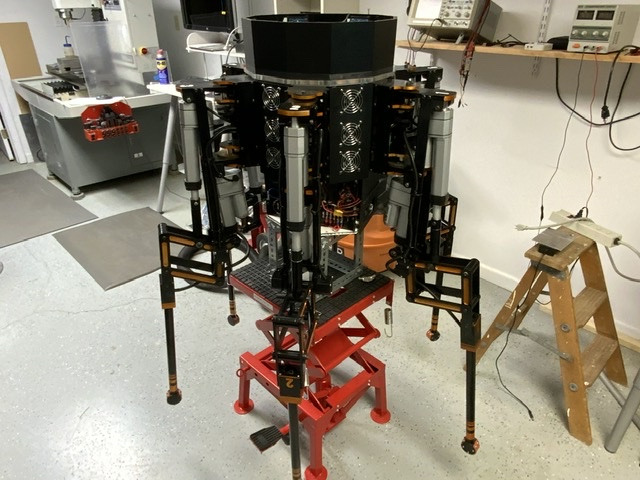
It's finally time to report on some success!
Stephen Moraco has been working with me and he developed another multiple port communications object for the P2. I incorporated the new code in the P2 master computer and after a few bumps where Stephen was able to explain the error of my ways, I am getting good feedback from the 6 leg controllers. I ran the P1 -> P2 com ports for a couple of hours with no issues seen.
This allows me to go back and figure out where I was before I stopped due to the communications issues, so time to read some of my old entries in here! (another good reason for keeping updates with these long distractions).
I believe I will step back a bit and do some work on getting a single leg to move in a straight line. This will test the speed of the P2 for running the IK calculations. It also can let me know if I am going down the right path in the way I am using IK.
On startup of the robot computers, the 6 leg controllers send the P2 master their current leg position, motor status, motor direction, whether the leg is touching ground. The lack of this information is where I first ran into trouble with the communications as the P2 master has to know where the individual legs are before it can do anything. I have a routine that converts the P1 leg angle data into an x,y grid value and checks if the leg is touching the ground. Since the robot legs are above the ground I can manually touch the leg down sensors and validate the leg registers the ground. All sensors but leg 1 are working, so will troubleshoot and fix this first.
It feels good to be able to move forward again.
Bob
Glad to hear that you got some help from @"Stephen Moraco" and are now moving forward again!
Jim
Troubleshooting the leg 1 ground touch sensor I found the sensor was working properly. The problem was when I re-coded the RGB lights for the new serial object, I messed up the array so the program was skipping over that light each time. All fixed now so moving on to the next item.
Next step is to make sure the P2 -> P1 communications is in order. This is a single P2 transit port that is wired to all the P1s. The P2 transmits movement requests in the format “$,LegNumber, FemurAngle, TibiaAngle, CoxaAngle, LegDown”. The “$” is the start indicator, “LegNumber” is what the P1’s look for. The motor angles are next, followed by “LegDown” which tells the P1 whether or not to go to the requested position or stop movement once the leg down sensor actuates.