@DiverBob said:
EDIT 2: Ever had a day when everything goes bad? Today was that day for me. I made what seemed to be fairly simple code changes, uploaded the changes and actually made the situation much worse!
That is a rather perfect description of my every day with my... let's call it... iterative coding style.
Couldn’t fix the random leg movements so I ended up removing the new code added to the individual leg controllers. Tested and now its back to its normal random leg movement during P2 startup.
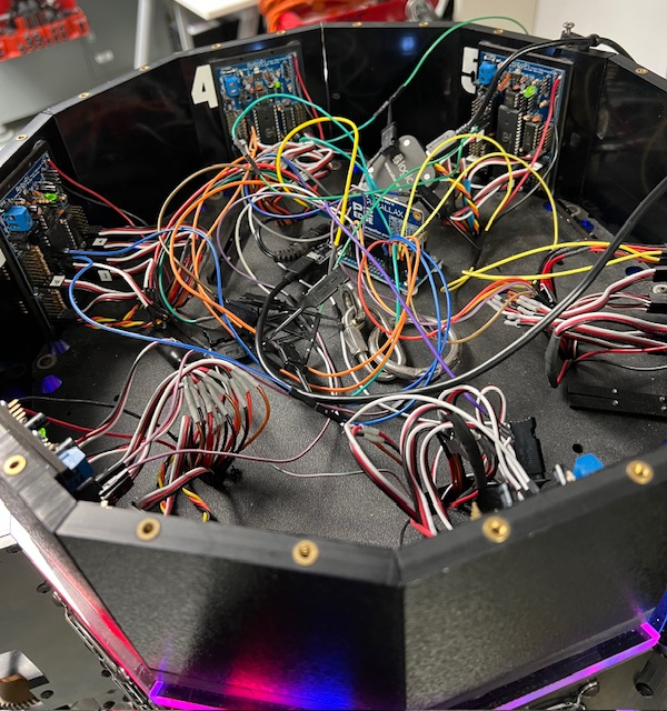
Thinking it through, when the P2 is restarted with a new program, all the P1 controllers are already up and running. At this point they are in a loop waiting for a valid movement command from the P2 which is formatted like ‘$,xxx,xxx,xxx,x’. The leg controller software is supposed to reject any command that isn’t in this format.
The movement is happening during the P2 startup routine, where the RGB lights are started on their cog and the 8 port communications is started. It seems to be glitching right after the 8 port comm is initialized, I’m trying to figure out how to test this hypothesis next using the logic analyzer.
Another possibility is that the HB-25 motor controllers are getting some type of random pulse which would cause a motor to actuate. Unlike a servo, the HB-25’s only require a single pulse in the 1 to 2 millisecond range to activate and they stay activated until told otherwise. That scenario seems plausible as the motors tend to move to the fullest extent of travel when this happens. The motor that gets activated most often is the coxa motor, followed by the tibia and then femur. It is rare that more than one motor per leg is affected and typically 2 to 3 legs are affected. Once the P2 program completes its startup the software works as designed and I don’t see random movements.
Interesting but frustrating problem to solve so I can continue.
And just to make things a bit more interesting, 3 of the P1 controllers will allow me to upload the flash memory but I get a validation error when loading the EEPROM. I will swap out a P1 DIP chip and see if this still happens using a never previously used P1, pretty sure I have an extra P1 laying around…
Hm, could not find information about HB-25 on Parallax's site. I wonder if a pull down resistor at the servo pulse input might make sense to avoid pulses when the P1 output pin is in floating state? I would try 1k to GND.
Here I found a description of the back-emf speed measurement, that I meant in post #1076 : https://acroname.com/articles/back-emf-motion-feedback . I have used this kind of thing and I am impressed how well it works.
(((Please forgive me, that I repeat, that working with Forth would fit your experimental working style and this project so very well. You could try out things so very much faster. Also writing and immediately testing small building blocks of code from bottom up helps a great deal in my experience.)))
After trying various ideas at both the P2 master and P1 Leg Controllers, I gave up and reverted back to the previous saved revision for the P2 code. It ran fine without any of the extraneous leg movements I was seeing before.
Now I have to slowly copy over some of the critical code changes from the previous version and figure out what change actually started this mess!
I incorporated most of the code from the previous version into a new working version. Code is working fine with leg 1 moving in a straight line with little to no jerking. Still tweaking the variables to see how everything impacts each other. Right now the intermediate step distance is 10mm, intermediate step time is 30 milliseconds, on a step length of 200mm at 45 degrees.
I tested code for stopping the leg if the leg touches the ground before it reaches the commanded position. This test was successful.
Next tests include moving 2 to 3 legs at one time along a straight path based on the direction the centerline of the body is moving.
However before I carry on with the leg movements, I'm still figuring out where the random leg movements during P2 startup are coming from. The P1's are already up and running but when I upload a P2 update, during the startup of the P2 there are occasionally random movement of 1 or more legs. This is happening before the P2 code starts sending out commands. Once the P2 code is up and running there is no further random movements. The P1 controller code is supposed to reject anything not in the correct format.
The leg movement occurs during the port startup, so starting with commenting out the P2 comms setup to the P1's definitely stops any leg movement. Initializing the serial ports results in occasional movement. Since I am using the isp_octoport_serial.spin2, the first step is to define the 6 ports (.Addport). The movement comes during this process. (I commented out the serial port .start()). Review of the serial port Addport() code is mostly setting up variables and buffers for use. The last part of the Addport() is the smart pin setup for the serial ports. The smart pin setup is about the only spot that could be sending out these signals. Normally the next step after setup of the serial ports the start() method but I see movement even if the start() is disabled.
The P1 code needs to be checked out as serial inputs from the P2 that don't match the proper format should be rejected. It may be easier to just ensure that the bad input isn't being passed on to the motor controllers in the first place rather than trying to track down something related to the P2 SmartPin setup.
For my own remote motion MCUs, I adopted the protocol from the PICservo (the PDF I posted in this thread).
I have this on many factory production machines, running @230KBaud (overkill). It's rock-solid on 4-wire RS485.
I found it amusing that a young engineer, responsible for their CNC department, had only one question for me, after three years: "How come I never need to reboot your control?"
The command packets have the following structure:
Header byte (always 0xAA)
Module Address byte (0 - 255)
Command byte
Additional Data bytes (0 - 15 bytes)
Checksum byte (8-bit sum of the Module Address byte through the last additional data byte)
The Header byte is used to signal the beginning of a command packet. When waiting for a new
command, each module will ignore any incoming data until it sees a Header byte.
The Module Address byte is the address of the target module. The address can be an individual
address, or the group address for the module. (See Group Commands below.)
The Command byte is broken up into an upper nibble (4 bits) and lower nibble (4 bits). The lower
nibble contains the command value (0 - 15), and the upper nibble contains the number of additional
data bytes required for that command (0 - 15). It is up to the host to insure that the upper nibble
matches the number of additional data bytes actually sent.
The Additional Data bytes contain the specific data which may be required for a particular command.
Many commands have a “control” or “mode” byte in addition to other parameters required for the
command. Some commands require no additional data. It is up to the host to make sure that the
proper number of additional data bytes is sent for a particular command, and that the upper nibble of
the command byte is equal to this number.
Once a module receives a complete packet, and the Address byte matches its address, it will verify
the checksum and immediately (within 0.51 milliseconds) begin to process the command. If there is a
checksum error in the command packet or any other sort of communications error (framing, overrun),
If only a single PIC-SERVO controller is used, the PIC-SERVO’s communications port can be operated as an RS232
port, with TX and RX connected to an RS232 transceiver rather than to an RS485 transceiver. In this case, the
TX_ENABLE output is not used and may be left open.
the command will not be executed, but a status packet will still be returned. If there are no errors, the
command will then be executed and a status packet returned. (Note that motion commands will
initiate the motion and return a status packet immediately without waiting for the motion to finish.)
The status packets have the following structure:
Status byte
Additional Status Data bytes (programmable)
Checksum byte (8-bit sum of all the bytes above)
The Status byte contains basic information about the state of the module, including whether or not the
previous command had a checksum error.
I determined that the spurious signals are originating with the P2 smart pins when they are setup for serial use. Since there doesn’t seem to be any way to stop this from happening on the P2 side, I started working on blocking the signal coming into the P1 controllers. Since the P1’s are already up and running and looking for a signal from the P2, apparently my code was passing through the spurious signals. I confirmed that when I accidentally stopped responding to the P2 signals in the code. At that point the motors were not responding to anything the P2 was outputting. Now I know that the P2 serial input isn’t being interpreted correctly in all cases by the P1 code, I will be going over that part of the code and see what I can do.
Back to coding!
Got away for a bit so time to fix the last set of issues.
With the information I got from messing up the leg controller program, I narrowed down the spurious leg movement issue and re-wrote the leg controller serial input routine. I've run several tests and not once has any leg moved or twitched while the P2 is loading a new program. The only problem I saw was the controllers for leg #5 and #6 both failed the EEPROM verify when I tried to load the program update. There is no issue with loading RAM with the same program so not sure what is causing this.
Will be going back to my testing routine, this is a series of 12 test routines that that check every aspect of the leg controllers and P2 control system. Each leg is tested individually and as a group, each encoder is checked against expected values, the legdown sensor is verified, the ability to move a single leg in a straight line is the last test so far. This allows quicker testing of basic functions each time I make any fundamental code changes to the P2 or P1 programs. Moving a test leg in a straight line identified issues that had to be resolved and I think I am close to success now. I have been able to move the leg 200mm in a straight line, now I have to try different input angles and distances to determine if there are interference issues that I haven't thought about. One mistake I made in the mechanical leg design is that the tibia minimum angle is 0 degrees. This limits the full range of motion while walking since the leg tip can not bend underneath the leg at all. This means the total leg travel distance for some angles will be limited so walking will be slower than I originally thought. Fixing this problem involves having to machine new tibia motor mounting brackets. Unfortunately these were the most difficult to design and machine items since all sides of the bracket has to be machined.
Still continuing on with testing leg movements. I’ve been concentrating on movements involving a single leg so far, like checking software leg constraints, maximum leg motions in each axis and test leg sensors. So far I have written 7 individual tests that each leg is put through to verify software and hardware setups.
The most difficult routine has been moving a leg in a straight line. When I first started coding this I found the potentiometer feedback built-in to the leg motors was very inaccurate and this required me to switch over to magnetic encoders with a 0.04º resolution. This required designing and mounting encoders for each axis. At this point the straight line movement routine seems to be working on a single leg pretty well. This was after using suggestions from other readers about incorporating a fixed time frame during each motor movement. This has resulted in a much smoother motor movement over the travel distance.
I’m ready to start moving more than one leg at a time now. For this the code will calculate all 6 leg movements first and then output the movement commands to each leg at the same time. I’m looking into using the new Data Structures as a way of keeping track of these. All the calculations have to be completed within the time interval (30 milliseconds seems to be working the best so far) so the commands can be output when the timer interval expires.
Baby steps but always getting closer to the goal!
Had a long break from the robot with our summer travels (Newfoundland this time!) but back to work on coding.
Spent some time reviewing my notes from before the break, then spent time getting reacquainted with the code. After that I was ready to get started again.
Starting with the test that moves a single leg tip in a straight line, previously the leg was not always ending up in the same location. This was because the code used the initial leg x,y,z position, would move the leg in a series of short increments until it reached the final destination. Each increment the leg moved, the code got the new leg position and then added in the next leg increment. Since these were relatively small leg movements sometimes the motors hadn't really moved the leg much by the time the next command was reached. So eventually the last increment resulted in a big movement to the final position.
This has been changed so it starts with the initial actual position but now uses the calculated position for each intermediate step. This means if a motor hasn't moved as much as it should, the next movement command for the motor results in a larger differential (error) value so the motor PID routine pushes that motor harder to catch up. Overall this appears to smooth the movement out.
@RS_Jim said:
@DiverBob ,
Any recent progress?
Jim
Hi there Jim! I haven’t been spending much time with the robot as we had a bunch of needed inside/outside house repairs that needed to be done so that was taking up all my time. I got caught up last week and finally turned on the robot and code to go through it again.
I had code that allowed a leg to move in a straight line but I found that it was going off and moving in different straight lines each time. To check this out I changed the code up so that instead of calculating a position and having the leg move to that position and repeating, I created an array to store all movement commands up front and then increment through the array to send the commands off. It appears that small errors in motor movements are accumulating during the step which results in larger errors later. Using an array to store movements allows me to re-use the same values each time and not let small errors to accumulate over time.
I also determined that the code that converted the current motor angles back to XYZ values didn’t seem to be working consistently which resulted in errors also. Yesterday I started re-writing that routine from scratch and came up with a faster and what appears to be more accurate conversion routine. It needs some more testing with different input values which I hope to do today.
Lastly there appears to be a calibration issue at least on leg #1, it isn’t going back to the correct starting point each time which throws off all the other calculations….
What I thought was a calibration error since Leg 1 wasn't going to the right start location, actually appears to be a deeper communications issue. I connected directly to the P1 controller for leg 1 and found that manually entering a motor position, the leg was going to the expected spot. So it wasn't a calibration issue. This leads me to believe the movement string transmitted from the P2 to the P1 is either not transmitting correctly or is being interpreted by the P1 correctly. I need to put the logic analyzer on the transmit line and verify the correct movement string is going through. If the P1 is receiving the right commands, then there is an issue in the P1 interpreter that breaks the input movement string into individual motor commands.
@DiverBob
welcome back!
I know only too well about those pesky repairs. We moved to a new location 1 year ago this Friday and have spent money like a drunken sailor. Biggest issue single pane windows in the Phoenix area. AC bills a killer. Miny $K later thermal transmission down to 4%.
Looking forward to updates.
Jim
@DiverBob said:
What I thought was a calibration error since Leg 1 wasn't going to the right start location, actually appears to be a deeper communications issue. I connected directly to the P1 controller for leg 1 and found that manually entering a motor position, the leg was going to the expected spot. So it wasn't a calibration issue. This leads me to believe the movement string transmitted from the P2 to the P1 is either not transmitting correctly or is being interpreted by the P1 correctly. I need to put the logic analyzer on the transmit line and verify the correct movement string is going through. If the P1 is receiving the right commands, then there is an issue in the P1 interpreter that breaks the input movement string into individual motor commands.
The method described in the PIC-servo document that I posted would solve all the problems. I have many CNC machines using this and have never even experienced a checksum error and the axis coordination is dead-nuts.
16 axes on a single UART @115KBaud.
@Mickster said:
The method described in the PIC-servo document that I posted would solve all the problems. I have many CNC machines using this and have never even experienced a checksum error and the axis coordination is dead-nuts.
16 axes on a single UART @115KBaud.
I incorporated a lot of the ideas that the document talked about and that did improve the error handling pretty well. It was hard to test as the error didn’t show up all the time. It wasn’t until I found a movement sequence where I could re-create the error reliably that I found a very subtle coding error. I fixed that problem for the femur motor and it stopped doing that particular movement. The coax motor has a subtle error that I still need to figure out what triggers it as its PID is set up slightly differently than the femur and tibia motors. That will be a problem to work on tomorrow as it seems we are about to get hit with a pretty heavy lake effect snowstorm overnight so working on that is better than going outside where it is 27ºF and 50-60 mph winds blasting the house!
Craig, I was wondering if it would be possible to see a copy of your PID code setup if it isn’t proprietary. It would be interesting to see how your approach is different from my setup.
Can you believe I actually miss SE-MI this time of year..... Love it
I had acreage in Clio and from 15th November, I'd be 25' up a tree at 5am every day
I'm in dreary old England atm and people are constantly complaining "it's cold"
I wish I was your neighbor, pretty sure we'd have this thing doing (intentional) back-flips by now
I'd be honored to help-out any way I can and I don't do proprietary anything
I'm currently on-site and up to my ears but I'll be back at base tomorrow.
I wish I was your neighbor, pretty sure we'd have this thing doing (intentional) back-flips by now:D
I could use a neighbor to who wanted to help out! I have a few friends doing FIRST Robotics but no one that does anything outside of that. So this has been mostly a one man show with lots of input from the Parallax forums.
Anyway, getting down to running more tests where I’m putting in specific movement commands and making sure the leg goes to the requested position. I use one specific leg position, ‘$,1,900,0,900,0’, as a starting point it is easy to visually see if the leg is mechanically in the right position. This command puts the femur angle at 90.0º, tibia at 0º, and coax at 90.0º. It’s fairly easy to see if the leg isn’t right. Other positions require using rulers to verify x and y positions. I use this position as the starting point for walking so the ability to return to this location is critical for future walking.
Time to head back down to the basement and test some more. Miskster, looking forward to seeing your PID code setup too!
After several days of troubleshooting I found a couple more bugs that fixed some issues and now have introduced new problems. When I stopped today the P2 is sending a command to the Leg 1 P1 controller properly per viewing on the logic analyzer. The leg only moves a fraction of a second before it stops with no error message, just a timeout error. Controlling the leg directly from the P1 works great, it’s just when the P2 issues the command that there is a problem. After putting in some more debug statements, I am slowly getting the issue narrowed down but ran out of time today.
When I was getting frustrated this week, I did review a couple of methods that convert the angle values of each motor into X, Y and Z equivalents and then turn X,Y,Z back into motor angles. I decided to draw the logic out without referring to my original notes and came up with simpler math for the conversions and they helped shave an additional 7 milliseconds off routines that used them. Testing these methods has been going well (I did verify that this changeup didn’t impact the above issue).
I had to revert to an older version of the code and then used Notpad++ to compare the older working version with the new non-working code. With a lot of going back and forth I finally determined the primary issue started when I changed a loop count value from 25 to 10. I have a method that checks to see if the magnetic encoder for the motor has stopped changing. The purpose of the method is to remove power to the motor if it has stalled by checking if the encoder output value is changing or not. I used a value to 25 cycles through the loop to allow time for the motor to come up to speed and remove any backlash in the gears before cutting motor power. I had changed the value to 10 which doesn’t give the motor time enough to spin up and actually allow the encoder value to change.
I am continuing the code comparison as I made some other changes to fix other issues and I don’t want to lose the changes.
The code comparison feature in Notepad++ (its a free plug-in) is turning out to be very helpful. I've used it by comparing a working copy of the leg controller code to the version that isn't working to see the differences. So far I've gotten the Femur motor code to work again with the changes. Now I'm working on the Tibia motor code changes. It appears to be an error in the code that monitors if the tibia motor isn't moving, very similar to the issue on the Femur. This portion of the code is fairly simple and I can't find any obvious errors so far. I did take the precaution of saving the working tibia this time so I didn't lose the femur changes again... got to remember to save working code using a new version number before making more changes.
The hardest part of testing code changes is the need to continually change the propplug between the P1 and P2 boards each time. To make a P1 change, the plug is moved to the P1 board, designate the current code as the top level object and save to RAM. Then physically move the prop plug to the P2 Edge, designate the master P2 code as the Top Level Object, load the changes and then test. If it doesn't work, then swap back to the P1. I don't think it is possible to connect both boards up at the same time, has anyone tried that? I'd have to change the comm port each time as far as I know.
I love it when you finally figure out one code issue, fix it, only to uncover other issues that were hidden! After a lot of hair pulling and nail biting, I got the Femur and Tibia control methods working properly. There does still seem to be another hidden issue where the tibia refuses to move even with a valid command, I haven’t figured out how to reproduce that error reliably so it will continue to be hidden for a while.
In the meantime got back to the process of moving the test leg in a straight line using a timed loop.
I’ve done the method 2 different ways: 1st, the start and endpoints of the leg move are calculated, the amount of change needed for each axis is computed and then sent to the leg before coming up with the next movement increment. The 2nd method is to compute all the leg movements prior to actual leg movement and store the values in an array. Then index through the array on a timer as the commands are executed. It seems that the array method has a smoother output and running the calculations up front doesn’t show a perceptible lag.
I’ve only experimented with a single array for one leg so far, will need the same array for the other 5 legs. This is where I think the new STRUCTURE command could be more efficient so that will be the next code area for me to test out.
We are going to take a short break from our lovely Michigan weather and go find someplace warm for a while but will be working on the coding on our trip.
Sorry to hear that robot is going into storage. Was hoping to see it walk. I have been following project since first post. Guess that will not happen in my lifetime. (almost 82)
Jim
I’m still working on it, it will be one of the last things to leave the house! I plan on continuing work on it in the meantime. Besides, we still have work to do on the house to get it ready to put on the market and downsizing a lot of the ‘stuff’ we have accumulated over the last 30+ years we have lived there.
This will give me the opportunity to work on code for some of the other sensors that I want to add after it can walk, like LIDAR and strain gauges on the legs.
I’ve been getting little bits of time to work on the robot in between other projects. Latest issue was finding out that my main computer storage system, a Drobo 5N, the company went bankrupt and replacements/repair isn’t available. So the last few days I’ve been backing up the Terabytes of Drobo files over to a very large SSD. Just want to have a good backup just in case!
We are going to be traveling for a bit so I wanted to be able to work on some robot related items in my spare time. So I got a nice padded carry case for the laptop and lots of Parallax goodies to work on. Part of the plan was to have the robot be aware of its surroundings so I hope to get a LIDAR system up and running using a stepper to rotate the unit, enable a GPS circuit, and an accelerometer. So now I have a rainy day kit to play with.
On the robot itself, I’ve decided that the smoothest leg movement comes from loading an array for each leg for the movement and then using a timed loop to cycle through the array. All the leg movement calculations are done once just before leg movement so that time consuming task is performed once. I still need to try using the STRUCTURE setup, so far I’ve just defined 3 arrays of up to 50 elements for each leg. Coding is starting to get complicated. I think structures would simplify the looping routines. Just need to study more examples.
Lots of fun stuff to work with!
Where has the time gone! I didn’t realize I hadn’t posted since April of this year and it’s almost at the end of the year now. I’ve done some short videos but those showed some items that needed work so I haven’t posted any of them.
Needless to say I have still been working on the coding, just not as intently as there have been more and more other distractions that keep me out of the basement. Foremost is making preparations to sell the house and downsizing. So I’ve sold off almost all the CNC equipment in the shop so the robot physical design can’t make any drastic changes anymore!
I was unsuccessful setting up the STRUCTURE for the arrays so I reverted back to using just a large array. I found whenever I made changes to the individual leg controllers, I then had to run similar testing on the P2 master. So I consolidated all these little test programs together, added a lot of DEBUG output statements so now I get a consistent testing environment. Because of this I was able to identify a program bug where when the femur is moved to its greatest value, the femur motor would not move the leg resulting in a NOMOVE timeout error until the move command was sent again. Using the DEBUG I could see the move command come in, the motor starts up but lack of femur movement causes a timeout before all the ‘slop’ in the motor gear train can be taken up. I could insert a larger delay into the femur movement loop (simple solution) or create a flag that only adds extra time if the motor changes direction. So far I’m leaning toward the 2nd idea. Initial testing is inconsistent so it seems that I have to figure out the ‘right’ time period for the delay.
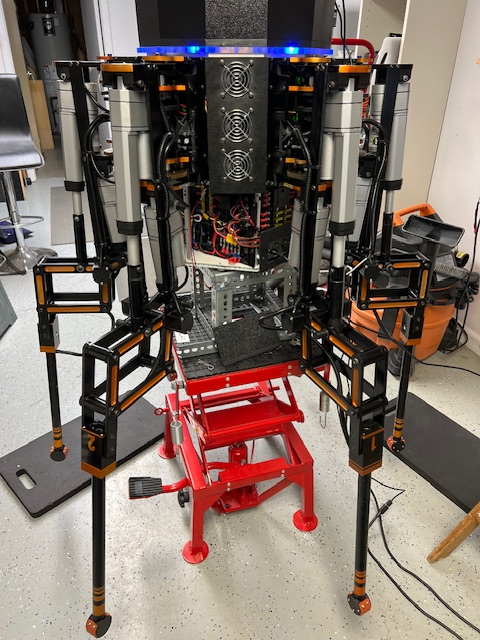
The primary robot project has been shut down now in preparation for selling the house and moving. All 6 legs have been removed and prepped for packing, the body is closed up, battery disconnected, and the programming computer/monitors are ready to be boxed up and moved into a climate controlled storage unit. So it might be a while before I get set back up again and can start working on it.
I still have a carry case of Parallax ‘stuff’ that travels with me so I can do some experimentation with the LIDAR and other planned auxiliary functions needed for the robot. So I’ll be creating some basic code for those elements that can be incorporated once the robot gets put back together again.
This has been a fun project that has taught me lots of new stuff from metal machining, CNC, anodizing, programming, and just having fun experimenting with different ideas. So I’m not ready to give it up, just need a new place to work!


Comments
Typically, the actuators would be disabled (no power) until the controller is fully initialized, loops closed and errors cancelled.
That is a rather perfect description of my every day with my... let's call it... iterative coding style.
Couldn’t fix the random leg movements so I ended up removing the new code added to the individual leg controllers. Tested and now its back to its normal random leg movement during P2 startup.
Thinking it through, when the P2 is restarted with a new program, all the P1 controllers are already up and running. At this point they are in a loop waiting for a valid movement command from the P2 which is formatted like ‘$,xxx,xxx,xxx,x’. The leg controller software is supposed to reject any command that isn’t in this format.
The movement is happening during the P2 startup routine, where the RGB lights are started on their cog and the 8 port communications is started. It seems to be glitching right after the 8 port comm is initialized, I’m trying to figure out how to test this hypothesis next using the logic analyzer.
Another possibility is that the HB-25 motor controllers are getting some type of random pulse which would cause a motor to actuate. Unlike a servo, the HB-25’s only require a single pulse in the 1 to 2 millisecond range to activate and they stay activated until told otherwise. That scenario seems plausible as the motors tend to move to the fullest extent of travel when this happens. The motor that gets activated most often is the coxa motor, followed by the tibia and then femur. It is rare that more than one motor per leg is affected and typically 2 to 3 legs are affected. Once the P2 program completes its startup the software works as designed and I don’t see random movements.
Interesting but frustrating problem to solve so I can continue.
And just to make things a bit more interesting, 3 of the P1 controllers will allow me to upload the flash memory but I get a validation error when loading the EEPROM. I will swap out a P1 DIP chip and see if this still happens using a never previously used P1, pretty sure I have an extra P1 laying around…
Hm, could not find information about HB-25 on Parallax's site. I wonder if a pull down resistor at the servo pulse input might make sense to avoid pulses when the P1 output pin is in floating state? I would try 1k to GND.
Here I found a description of the back-emf speed measurement, that I meant in post #1076 : https://acroname.com/articles/back-emf-motion-feedback . I have used this kind of thing and I am impressed how well it works.
(((Please forgive me, that I repeat, that working with Forth would fit your experimental working style and this project so very well. You could try out things so very much faster. Also writing and immediately testing small building blocks of code from bottom up helps a great deal in my experience.)))
After trying various ideas at both the P2 master and P1 Leg Controllers, I gave up and reverted back to the previous saved revision for the P2 code. It ran fine without any of the extraneous leg movements I was seeing before.
Now I have to slowly copy over some of the critical code changes from the previous version and figure out what change actually started this mess!
I incorporated most of the code from the previous version into a new working version. Code is working fine with leg 1 moving in a straight line with little to no jerking. Still tweaking the variables to see how everything impacts each other. Right now the intermediate step distance is 10mm, intermediate step time is 30 milliseconds, on a step length of 200mm at 45 degrees.
I tested code for stopping the leg if the leg touches the ground before it reaches the commanded position. This test was successful.
Next tests include moving 2 to 3 legs at one time along a straight path based on the direction the centerline of the body is moving.
However before I carry on with the leg movements, I'm still figuring out where the random leg movements during P2 startup are coming from. The P1's are already up and running but when I upload a P2 update, during the startup of the P2 there are occasionally random movement of 1 or more legs. This is happening before the P2 code starts sending out commands. Once the P2 code is up and running there is no further random movements. The P1 controller code is supposed to reject anything not in the correct format.
The leg movement occurs during the port startup, so starting with commenting out the P2 comms setup to the P1's definitely stops any leg movement. Initializing the serial ports results in occasional movement. Since I am using the isp_octoport_serial.spin2, the first step is to define the 6 ports (.Addport). The movement comes during this process. (I commented out the serial port .start()). Review of the serial port Addport() code is mostly setting up variables and buffers for use. The last part of the Addport() is the smart pin setup for the serial ports. The smart pin setup is about the only spot that could be sending out these signals. Normally the next step after setup of the serial ports the start() method but I see movement even if the start() is disabled.
The P1 code needs to be checked out as serial inputs from the P2 that don't match the proper format should be rejected. It may be easier to just ensure that the bad input isn't being passed on to the motor controllers in the first place rather than trying to track down something related to the P2 SmartPin setup.
For my own remote motion MCUs, I adopted the protocol from the PICservo (the PDF I posted in this thread).
I have this on many factory production machines, running @230KBaud (overkill). It's rock-solid on 4-wire RS485.
I found it amusing that a young engineer, responsible for their CNC department, had only one question for me, after three years: "How come I never need to reboot your control?"
Craig
I determined that the spurious signals are originating with the P2 smart pins when they are setup for serial use. Since there doesn’t seem to be any way to stop this from happening on the P2 side, I started working on blocking the signal coming into the P1 controllers. Since the P1’s are already up and running and looking for a signal from the P2, apparently my code was passing through the spurious signals. I confirmed that when I accidentally stopped responding to the P2 signals in the code. At that point the motors were not responding to anything the P2 was outputting. Now I know that the P2 serial input isn’t being interpreted correctly in all cases by the P1 code, I will be going over that part of the code and see what I can do.
Back to coding!
Got away for a bit so time to fix the last set of issues.
With the information I got from messing up the leg controller program, I narrowed down the spurious leg movement issue and re-wrote the leg controller serial input routine. I've run several tests and not once has any leg moved or twitched while the P2 is loading a new program. The only problem I saw was the controllers for leg #5 and #6 both failed the EEPROM verify when I tried to load the program update. There is no issue with loading RAM with the same program so not sure what is causing this.
Will be going back to my testing routine, this is a series of 12 test routines that that check every aspect of the leg controllers and P2 control system. Each leg is tested individually and as a group, each encoder is checked against expected values, the legdown sensor is verified, the ability to move a single leg in a straight line is the last test so far. This allows quicker testing of basic functions each time I make any fundamental code changes to the P2 or P1 programs. Moving a test leg in a straight line identified issues that had to be resolved and I think I am close to success now. I have been able to move the leg 200mm in a straight line, now I have to try different input angles and distances to determine if there are interference issues that I haven't thought about. One mistake I made in the mechanical leg design is that the tibia minimum angle is 0 degrees. This limits the full range of motion while walking since the leg tip can not bend underneath the leg at all. This means the total leg travel distance for some angles will be limited so walking will be slower than I originally thought. Fixing this problem involves having to machine new tibia motor mounting brackets. Unfortunately these were the most difficult to design and machine items since all sides of the bracket has to be machined.
Still continuing on with testing leg movements. I’ve been concentrating on movements involving a single leg so far, like checking software leg constraints, maximum leg motions in each axis and test leg sensors. So far I have written 7 individual tests that each leg is put through to verify software and hardware setups.
The most difficult routine has been moving a leg in a straight line. When I first started coding this I found the potentiometer feedback built-in to the leg motors was very inaccurate and this required me to switch over to magnetic encoders with a 0.04º resolution. This required designing and mounting encoders for each axis. At this point the straight line movement routine seems to be working on a single leg pretty well. This was after using suggestions from other readers about incorporating a fixed time frame during each motor movement. This has resulted in a much smoother motor movement over the travel distance.
I’m ready to start moving more than one leg at a time now. For this the code will calculate all 6 leg movements first and then output the movement commands to each leg at the same time. I’m looking into using the new Data Structures as a way of keeping track of these. All the calculations have to be completed within the time interval (30 milliseconds seems to be working the best so far) so the commands can be output when the timer interval expires.
Baby steps but always getting closer to the goal!
Had a long break from the robot with our summer travels (Newfoundland this time!) but back to work on coding.
Spent some time reviewing my notes from before the break, then spent time getting reacquainted with the code. After that I was ready to get started again.
Starting with the test that moves a single leg tip in a straight line, previously the leg was not always ending up in the same location. This was because the code used the initial leg x,y,z position, would move the leg in a series of short increments until it reached the final destination. Each increment the leg moved, the code got the new leg position and then added in the next leg increment. Since these were relatively small leg movements sometimes the motors hadn't really moved the leg much by the time the next command was reached. So eventually the last increment resulted in a big movement to the final position.
This has been changed so it starts with the initial actual position but now uses the calculated position for each intermediate step. This means if a motor hasn't moved as much as it should, the next movement command for the motor results in a larger differential (error) value so the motor PID routine pushes that motor harder to catch up. Overall this appears to smooth the movement out.
Hi Bob,
This is is why we discretize (sample) the motion profile.
Craig
@DiverBob ,
Any recent progress?
Jim
Hi there Jim! I haven’t been spending much time with the robot as we had a bunch of needed inside/outside house repairs that needed to be done so that was taking up all my time. I got caught up last week and finally turned on the robot and code to go through it again.
I had code that allowed a leg to move in a straight line but I found that it was going off and moving in different straight lines each time. To check this out I changed the code up so that instead of calculating a position and having the leg move to that position and repeating, I created an array to store all movement commands up front and then increment through the array to send the commands off. It appears that small errors in motor movements are accumulating during the step which results in larger errors later. Using an array to store movements allows me to re-use the same values each time and not let small errors to accumulate over time.
I also determined that the code that converted the current motor angles back to XYZ values didn’t seem to be working consistently which resulted in errors also. Yesterday I started re-writing that routine from scratch and came up with a faster and what appears to be more accurate conversion routine. It needs some more testing with different input values which I hope to do today.
Lastly there appears to be a calibration issue at least on leg #1, it isn’t going back to the correct starting point each time which throws off all the other calculations….
What I thought was a calibration error since Leg 1 wasn't going to the right start location, actually appears to be a deeper communications issue. I connected directly to the P1 controller for leg 1 and found that manually entering a motor position, the leg was going to the expected spot. So it wasn't a calibration issue. This leads me to believe the movement string transmitted from the P2 to the P1 is either not transmitting correctly or is being interpreted by the P1 correctly. I need to put the logic analyzer on the transmit line and verify the correct movement string is going through. If the P1 is receiving the right commands, then there is an issue in the P1 interpreter that breaks the input movement string into individual motor commands.
@DiverBob
welcome back!
I know only too well about those pesky repairs. We moved to a new location 1 year ago this Friday and have spent money like a drunken sailor. Biggest issue single pane windows in the Phoenix area. AC bills a killer. Miny $K later thermal transmission down to 4%.
Looking forward to updates.
Jim
The method described in the PIC-servo document that I posted would solve all the problems. I have many CNC machines using this and have never even experienced a checksum error and the axis coordination is dead-nuts.
16 axes on a single UART @115KBaud.
Craig
I incorporated a lot of the ideas that the document talked about and that did improve the error handling pretty well. It was hard to test as the error didn’t show up all the time. It wasn’t until I found a movement sequence where I could re-create the error reliably that I found a very subtle coding error. I fixed that problem for the femur motor and it stopped doing that particular movement. The coax motor has a subtle error that I still need to figure out what triggers it as its PID is set up slightly differently than the femur and tibia motors. That will be a problem to work on tomorrow as it seems we are about to get hit with a pretty heavy lake effect snowstorm overnight so working on that is better than going outside where it is 27ºF and 50-60 mph winds blasting the house!
Craig, I was wondering if it would be possible to see a copy of your PID code setup if it isn’t proprietary. It would be interesting to see how your approach is different from my setup.
Hi Bob,
Can you believe I actually miss SE-MI this time of year..... Love it")

I had acreage in Clio and from 15th November, I'd be 25' up a tree at 5am every day
I'm in dreary old England atm and people are constantly complaining "it's cold"
I wish I was your neighbor, pretty sure we'd have this thing doing (intentional) back-flips by now
I'd be honored to help-out any way I can and I don't do proprietary anything
I'm currently on-site and up to my ears but I'll be back at base tomorrow.
Craig
I could use a neighbor to who wanted to help out! I have a few friends doing FIRST Robotics but no one that does anything outside of that. So this has been mostly a one man show with lots of input from the Parallax forums.
Anyway, getting down to running more tests where I’m putting in specific movement commands and making sure the leg goes to the requested position. I use one specific leg position, ‘$,1,900,0,900,0’, as a starting point it is easy to visually see if the leg is mechanically in the right position. This command puts the femur angle at 90.0º, tibia at 0º, and coax at 90.0º. It’s fairly easy to see if the leg isn’t right. Other positions require using rulers to verify x and y positions. I use this position as the starting point for walking so the ability to return to this location is critical for future walking.
Time to head back down to the basement and test some more. Miskster, looking forward to seeing your PID code setup too!
After several days of troubleshooting I found a couple more bugs that fixed some issues and now have introduced new problems. When I stopped today the P2 is sending a command to the Leg 1 P1 controller properly per viewing on the logic analyzer. The leg only moves a fraction of a second before it stops with no error message, just a timeout error. Controlling the leg directly from the P1 works great, it’s just when the P2 issues the command that there is a problem. After putting in some more debug statements, I am slowly getting the issue narrowed down but ran out of time today.
When I was getting frustrated this week, I did review a couple of methods that convert the angle values of each motor into X, Y and Z equivalents and then turn X,Y,Z back into motor angles. I decided to draw the logic out without referring to my original notes and came up with simpler math for the conversions and they helped shave an additional 7 milliseconds off routines that used them. Testing these methods has been going well (I did verify that this changeup didn’t impact the above issue).
I had to revert to an older version of the code and then used Notpad++ to compare the older working version with the new non-working code. With a lot of going back and forth I finally determined the primary issue started when I changed a loop count value from 25 to 10. I have a method that checks to see if the magnetic encoder for the motor has stopped changing. The purpose of the method is to remove power to the motor if it has stalled by checking if the encoder output value is changing or not. I used a value to 25 cycles through the loop to allow time for the motor to come up to speed and remove any backlash in the gears before cutting motor power. I had changed the value to 10 which doesn’t give the motor time enough to spin up and actually allow the encoder value to change.
I am continuing the code comparison as I made some other changes to fix other issues and I don’t want to lose the changes.
The code comparison feature in Notepad++ (its a free plug-in) is turning out to be very helpful. I've used it by comparing a working copy of the leg controller code to the version that isn't working to see the differences. So far I've gotten the Femur motor code to work again with the changes. Now I'm working on the Tibia motor code changes. It appears to be an error in the code that monitors if the tibia motor isn't moving, very similar to the issue on the Femur. This portion of the code is fairly simple and I can't find any obvious errors so far. I did take the precaution of saving the working tibia this time so I didn't lose the femur changes again... got to remember to save working code using a new version number before making more changes.
The hardest part of testing code changes is the need to continually change the propplug between the P1 and P2 boards each time. To make a P1 change, the plug is moved to the P1 board, designate the current code as the top level object and save to RAM. Then physically move the prop plug to the P2 Edge, designate the master P2 code as the Top Level Object, load the changes and then test. If it doesn't work, then swap back to the P1. I don't think it is possible to connect both boards up at the same time, has anyone tried that? I'd have to change the comm port each time as far as I know.
I love it when you finally figure out one code issue, fix it, only to uncover other issues that were hidden! After a lot of hair pulling and nail biting, I got the Femur and Tibia control methods working properly. There does still seem to be another hidden issue where the tibia refuses to move even with a valid command, I haven’t figured out how to reproduce that error reliably so it will continue to be hidden for a while.
In the meantime got back to the process of moving the test leg in a straight line using a timed loop.
I’ve done the method 2 different ways: 1st, the start and endpoints of the leg move are calculated, the amount of change needed for each axis is computed and then sent to the leg before coming up with the next movement increment. The 2nd method is to compute all the leg movements prior to actual leg movement and store the values in an array. Then index through the array on a timer as the commands are executed. It seems that the array method has a smoother output and running the calculations up front doesn’t show a perceptible lag.
I’ve only experimented with a single array for one leg so far, will need the same array for the other 5 legs. This is where I think the new STRUCTURE command could be more efficient so that will be the next code area for me to test out.
We are going to take a short break from our lovely Michigan weather and go find someplace warm for a while but will be working on the coding on our trip.
Sorry to hear that robot is going into storage. Was hoping to see it walk. I have been following project since first post. Guess that will not happen in my lifetime. (almost 82)
Jim
I’m still working on it, it will be one of the last things to leave the house! I plan on continuing work on it in the meantime. Besides, we still have work to do on the house to get it ready to put on the market and downsizing a lot of the ‘stuff’ we have accumulated over the last 30+ years we have lived there.
This will give me the opportunity to work on code for some of the other sensors that I want to add after it can walk, like LIDAR and strain gauges on the legs.
I’ve been getting little bits of time to work on the robot in between other projects. Latest issue was finding out that my main computer storage system, a Drobo 5N, the company went bankrupt and replacements/repair isn’t available. So the last few days I’ve been backing up the Terabytes of Drobo files over to a very large SSD. Just want to have a good backup just in case!
We are going to be traveling for a bit so I wanted to be able to work on some robot related items in my spare time. So I got a nice padded carry case for the laptop and lots of Parallax goodies to work on. Part of the plan was to have the robot be aware of its surroundings so I hope to get a LIDAR system up and running using a stepper to rotate the unit, enable a GPS circuit, and an accelerometer. So now I have a rainy day kit to play with.
On the robot itself, I’ve decided that the smoothest leg movement comes from loading an array for each leg for the movement and then using a timed loop to cycle through the array. All the leg movement calculations are done once just before leg movement so that time consuming task is performed once. I still need to try using the STRUCTURE setup, so far I’ve just defined 3 arrays of up to 50 elements for each leg. Coding is starting to get complicated. I think structures would simplify the looping routines. Just need to study more examples.
Lots of fun stuff to work with!
Where has the time gone! I didn’t realize I hadn’t posted since April of this year and it’s almost at the end of the year now. I’ve done some short videos but those showed some items that needed work so I haven’t posted any of them.
Needless to say I have still been working on the coding, just not as intently as there have been more and more other distractions that keep me out of the basement. Foremost is making preparations to sell the house and downsizing. So I’ve sold off almost all the CNC equipment in the shop so the robot physical design can’t make any drastic changes anymore!
I was unsuccessful setting up the STRUCTURE for the arrays so I reverted back to using just a large array. I found whenever I made changes to the individual leg controllers, I then had to run similar testing on the P2 master. So I consolidated all these little test programs together, added a lot of DEBUG output statements so now I get a consistent testing environment. Because of this I was able to identify a program bug where when the femur is moved to its greatest value, the femur motor would not move the leg resulting in a NOMOVE timeout error until the move command was sent again. Using the DEBUG I could see the move command come in, the motor starts up but lack of femur movement causes a timeout before all the ‘slop’ in the motor gear train can be taken up. I could insert a larger delay into the femur movement loop (simple solution) or create a flag that only adds extra time if the motor changes direction. So far I’m leaning toward the 2nd idea. Initial testing is inconsistent so it seems that I have to figure out the ‘right’ time period for the delay.
The primary robot project has been shut down now in preparation for selling the house and moving. All 6 legs have been removed and prepped for packing, the body is closed up, battery disconnected, and the programming computer/monitors are ready to be boxed up and moved into a climate controlled storage unit. So it might be a while before I get set back up again and can start working on it.
I still have a carry case of Parallax ‘stuff’ that travels with me so I can do some experimentation with the LIDAR and other planned auxiliary functions needed for the robot. So I’ll be creating some basic code for those elements that can be incorporated once the robot gets put back together again.
This has been a fun project that has taught me lots of new stuff from metal machining, CNC, anodizing, programming, and just having fun experimenting with different ideas. So I’m not ready to give it up, just need a new place to work!
Not leaving beautiful Michigan I hope")