I think my coding notes are getting better, this is the fastest I’ve been able to review the code after a long break and figure out what I had been working on!
Got the red RGB light issue figured out and resolved. This then exposed another unusual light pattern where a white light kept flashing intermittently on each leg. That one was harder to troubleshoot but increasing the buffer size on the P2 communications loop from the leg controllers solved that problem. The feedback data flow from the leg controllers was getting corrupted intermittently also so that was solved by adding code to the input routine to ignore inputs that didn’t have the proper start characters.
I added in the Inverse Kinematics (IK) formulas I developed for the P2 along with trig routines that use integer math instead of Floating Point math in an effort to improve calculation speeds.
Next on the agenda is testing the IK using a single leg and see if I can get it to move in a straight line!
So far there is no danger that the robot will leave the basement on its own!
While testing the individual legs I was getting movements that indicated to me that the legs needed to be re-calibrated. When I would set the femur to 90 degrees the actual angle would be a bit over 100 degrees with similar results on the tibia.
I tried my normal calibration routine and was getting no where, actually the physical angle positions were getting even further away from the expected positions. This morning I really got into the code math behind calculating the angles.
The code first off determines the mathematical slope where the magnetic encoder output at the minimum and maximum angles are compared to the actual degrees the leg is at when at the minimum and maximum mechanical positions. This gives the slope of the line (assumed to be a linear function), or in terms of the program, how many counts of the encoder do you get for each angle change. When a move request is entered, the desired angle is supplied. This is used to calculate the target encoder value based on the slope. The motor is engaged and runs until it gets to the desired position. There is always some over- or under-shoot in this mechanical process so the next step is taking the final encoder value to calculate the actual angle the leg ends up at.
With that information I found that I was using 2 different methods to get the target and the final position values. The difference was in whether I used the minimum or maximum physical angle value. Although mathematically it doesn’t make a difference, in code I was ending up with 2 answers that were close but not close enough.
I fixed the code for the femur so next is fixing the tibia code to match. I’ve always seen small discrepancies but it isn’t until all legs are moving together that it became noticeable that each leg was moving to different positions.
I’ve been working on calibrating the legs which can be a tedious task. I wrote a calibration routine that makes it much simpler now which helps a lot.
I started with leg 1 and worked my way around the robot, taking each leg in order. When I got to leg 3, I found the tibia motor was not responding. After some troubleshooting I removed the leg and put it on the bench for testing the motor. The motor would not turn even with voltage applied directly to the motor leads. So I removed the actuator from the robot and then disassembled the motor. The motor is a 12v brushed motor and I found the brushes were not contacting the rotor commutator. This required removal of the brushes and some filing of the nylon brush holders until the brushes were free to move again. Once the motor was reassembled, power was applied and the motor is working again. It appeared the nylon brush holders got overheated and constricted the brush movement. After this I was able to reattach leg 3 and finish the leg 3 calibration and moved on.
I got to leg 5 and while calibrating the tibia encoder settings, I got a port 3 comm error when I tried to upload to RAM. A reboot and other tests determined the problem is on the Dell Win 10 computer side so have to figure that one out yet. I asked the question in the P1 forum side, hopefully someone has some ideas of how to proceed!
I have seen the melted brush holder issue before and added coding to shutdown the motor controllers if it detects the motor encoder isn’t changing, don’t know if leg 3 is just showing an issue from before the code change or if it is recent. The motor wasn’t hot to the touch and the robot is suspended on the test stand so it wasn’t even supporting its own weight. I did some quick searches on-line for brushless linear actuators but didn’t see anything useful for my situation.
I’m on hold for a bit until I get the Prop Tool to talk to the RoboPi boards again, hopefully it won’t take long to fix
@msrobots said:
if your motors get hot without load you have a torque/friction problem. How hard is it to move the legs w/o motors attached?
WD40?
As for the com port try to remove the entry in the device manager, windows does bs there sometimes...
Mike
What I meant was that I checked the motor temperature and it was cool. The legs weren’t touching the ground so there is no load on them. The legs move very easily when the motors aren’t attached, every pivot point has a bearing so there is very little friction on any of the motors. I’m speculating that the heat damage was caused a few months ago when I was still using a P1 as the master and had the full weight on the legs. Due to some of the testing the tibia movements resulted in locked motor rotors on a couple of legs. At that time only one motor failed, this motor may have been damaged and finally got to a failure point. In the meantime I added code to detect locked rotors by monitoring change to the encoder output. If the encoder doesn’t change by more than a value of 5 over 5 cycles of the PID routine, the PID loop is exited. This also accounts for situations where the actuator actuates an internal limit switch and stops.
Thanks for the hint of checking the device manager and reset the com port there. I’ll give it a try next.
Well I am not a EE at all, I learn by burning things and not repeat it again.
One could say that I am a fan of your project. In one of your posts your said 'all legs moving' that is quite a 'step' after just testing them alone.
As for using the P2 as Central controller I think you are right, but I think there is no need to replace all the leg controllers, the P1 can handle that.
This is a very cool project and I hope I can see this thing walking some time.
Got the RoboPi P1 boards to talk to the computer again. Apparently the computer needed a full reboot vs just a restart. Anyway I’ve been able spend a few hours so far calibrating and fixing issues that have shown up. Got all but one fixed, the routine that is supposed to stop the motor if the magnetic encoder value doesn’t change (to prevent locked motor rotor issues and in the event the actuator activates its internal limit switch) is being triggered but the motor continues to run. In this case the motor angle position is 0 degrees and I want it to move to 52 degrees. PST shows the encoder output is not changing so this should stop the motor but the motor then runs until it actuates the actuator limit switch. Good puzzle to figure out!
Walked away from the code for a couple of hours and after coming back fresh, I almost immediately found one error. The tibia code was telling the femur motor to stop instead of the tibia motor! That fixed the issue where the tibia motor continued to run even after being told to stop.
That left the problem where the tibia motor never doesn't start running because the encoder didn't show any motor movement. I determined this only occurs after changing motor direction, a clear indication of mechanical backlash in the linear actuator internal gear train. The fix was to add 50 msec to the PID loop. Since delay this is only necessary when the motor has reversed direction, I added a new flag that is set when the motor direction reverses and 50 msec is only added to the loop during the first loop. That solved both problems found earlier.
One of the other things I have been working on is cleaning up the code to make it more readable and speed the code up. This requires adding more comments which help identify why some parts of the code are in there. I found myself removing some code that wasn't clear only to find out it's purpose later when testing. Not everything is immediately obvious as some code is needed because the computers are interfacing with mechanical systems which don't react as fast as the P1 can process. Good notes help reduce those mistakes!
Busy week, had some computer problems with the Prop Tool that took a bit of work to resolve. After some registry hacking fun, I was able to finally upload the latest code updates into all 6 leg controllers after finishing calibrating all the legs.
Started reviewing my old notes on how to make the legs move using Inverse Kinematics (IK) again. When I've been at this point before I've just used IK to control a single leg, mainly testing routines to allow the leg to move in a straight line. Past issues with getting consistent straight line leg movement is what lead me to adding the magnetic encoders vs the original potentiometers to improve leg position resolution/repeatability. It also put me on the road to create PID-like software in the controllers to get better leg movements vs the earlier motor control coding.
This leads to my current studies, how to get all 6 legs to move in a coordinated method so it can walk. To do that I have to combine each leg's coordinate system into a single coordinate system. The best way to do that is to imagine the center of the body as the 0,0 point of a X,Y grid. By moving the center of the body a given distance and angle, each leg will need to move the same distance and angle. This requires some precision starting measurements of the body to leg distances.
Going back through the CAD files I got the dimensions of the base plate the legs attach to along with the additional distance to the coxa pivot point as the starting point. I decided to start working in millimeters (mm) instead of inches so I can work with whole numbers in the coding, which should make coding easier. So each leg is 250 mm distance away from the body 0,0 coordinate. Using this info and the fact the legs are 60 degrees apart, sine and cosine gave the body coordinates for each leg position.
Next job is determining the formulas to convert a body position into each individual leg coordinate. I've studying some math examples to see how to apply the formulas to my setup. That pretty much brings you up to date with this weeks hexapod work. Hopefully by next week translating body to leg coordinates will be done and I can start coding that in for testing.
As a side note, after finding the issue with the motor brushes melting, did some searching to see if anyone makes affordable brushless linear actuators. So far I haven't found anything I can afford, apparently brushless linear actuators aren't a common item. Of course even if I found them that would entail a lot of work to modify the robot to install along with needing new motor controllers vs the HB-25's I have.... Maybe some day it can be an upgrade!
Yes, there has been progress but not a lot of time has been spent working on the robot this month, too many other projects around the house and outside needed to be completed before it starts snowing around here.
I believe I figured out the movement requirements and started to write them out here but I realized for it to be really understood I needed some diagrams to go along with the description. I got myself a nice graphics app for my iPad and have drawn up some sketches showing the various angles. Now I need to consolidate all my chicken scratching from several pieces of paper into one coherent description. I figure if I can describe the math process then it makes it much easier to code and even more importantly, much easier to understand what needs to be accomplished further down the line. I hope to get something put together this week and will post it then.
Snow is something that we southern Arizonans go north to visit if we are so inclined. I suspect that being gone all summer has something todo with the honeydo list as well.
Jim
After several days with pencil and paper I realized I was over-thinking how to translate body movement to leg movement. I believe I have a solution and have been checking it out manually using different inputs and my calculator! There are some assumptions used for these calculations:
All measurements are in mm instead of inches to keep all calculations as integers and no floating point calculations
all legs start at the 90º coxa and femur positions, tibia is at 0º
Distance from the center of the body to each coxa pivot point is 250mm
initial distance from the centerline of the coxa pivot point to the leg tip point is 216mm (tibia angle of 0º)
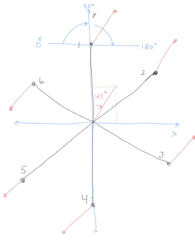
The ‘front’ of the hexapod is centered on Leg #1. It could be any position but this puts leg 1 at 0º, Leg 2 at 60º and so on for each of the legs when looking at the hexapod from an overhead view. Superimposing a XY grid over this view puts the XY 0,0 intercept point at the center of the hexapod body
Movement of the hexapod is calculated using the center of the body as the starting point. The user determines the direction of movement by inputing an X and Y value. This can be input via a remote joystick using potentiometers which give the appropriate values. Each leg needs to move in the same direction and for the same distance for a step for smooth operation. For this example I am only using the X and Y values of 64mm to determine a direction and stride length.
Get the movement angle. Given the X and Y values, tangent (tan) of the angle is determined.
Tan(angle) = opposite side/adjacent side. This is the direction the body is moving.
Stride length is the hypotenuse of the X and Y values. (Remember Geometry!)
Now we have a direction (45º) and distance (64mm). This based on the center of the hexapod body.
The body center movement is next translated for each leg. Each leg has its own independent coordinate system located around the body center.
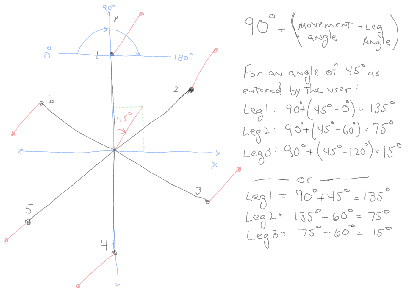
The leg has a 180º swing from one side to the other with 90º being the center point for the leg where it is sticking straight out from the body center. The Y axis for the leg is along this line that starts at the coxa pivot point. The X axis is the line along the 0º to 180º point. So X values that are positive are on the >90º side of the line and negative X values are on the <90º side.
In the example, the user requests a 45º movement. Leg 1 is the easiest to calculate as it is in line with the Y axis. If the black dot on the diagram is the current position of the leg tip, then 45º from that location is 90º + 45º, or 135º (leg coordinate goes from 0º to 180º with 90º being in line with the y axis).
The same formula is used to calculate leg 2 and 3 at 75º and 15º respectively. Leg 4, 5, 6 will have the same values as leg1, 2, and 3 so there is no need to calculate them separately. Of course there is always another method available, once you know leg 1 angle then by subtracting 60º from the value, leg 2 and 3 can be figured quickly.
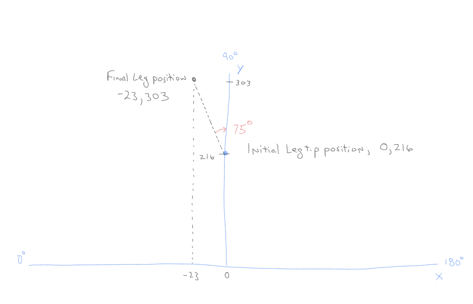
Now that the desired movement angle has been figured out, the distance each leg has to move is needed. The stride length was calculated at 90mm earlier. This is used to get the leg tip position in terms of X and Y for each leg. Leg 1 is the easiest to figure, since it is in the same plane as the user input, the X and Y values are 64mm. Figuring leg 2 requires some math. Leg 2 is at 75º with a stride of 90.
This gives a value of 23mm for the X axis and 87mm for the Y axis for the Leg 2 coordinate system. Leg 3 is calculated the same way based on an angle of 15º. Leg 4, 5, 6 have the same values as legs 1, 2, 3 since the angles are the same.
This gives the amount of movement the leg tip needs to move from its current location. However we also need to know where the leg tip is currently located in the XY coordinate. In this case we need to know the starting X and Y coordinates. Then add the new X and Y values to the start values to get the end point. For the starting coordinates we use the assumed values discussed at the beginning of the discussion. So initially each leg starts at 90º coxa position (X axis value of 0). The tibia angle is 0º so the leg tibia is perpendicular to the ground so the length along the Y axis is equal to the length of the femur plus the distance between the coxa pivot point and the femur pivot point (216mm). All initial leg positions are X=0, Y=216. To get the desired leg tip endpoint, add the initial XY values to the calculated values. For Leg 2, X = Xinitial + Xmovement and Y = Yinitial + Y movement.
Note: There are no negative Y axis values due to the design of the legs where the tibia can not physically move to less than 0º.
Note: X axis is negative on the left side and positive on the right side of the Y axis which is the 90º point. So calculated angles less than 90º require X values to be negative.
X= 0 + -23 = -23mm
Y= 216 + 87 = 303mm
There is one last step to this process. If the robot was just given the end point values to move to, it would not be pretty! The 3 motors on each leg move a slightly different speeds, the distances needed to move are different lengths so the result would be very jerky at best and potentially damaging to the robot legs at worse.
There are lots of ways to make this work but the method I chose is to break the move up into smaller chunks. In this case where the leg is moving 90mm from the initial position to the final position, break it into 5mm sections. So the leg moves 5mm along the path, waits for all motors to finish and then move another 5mm. Repeat this 18 times until the final endpoint is reached. Programmatically there are several ways to approach this, the way I did this initially using the P1 was compare the X and Y values. The larger value is divided by the resolution (5mm) to get the number of steps. The smaller value is divided by the same number of steps. Then a loop is used to increment the X and Y values and the results are run through the IK engine. This ends up being a ‘stairstep’ approach to smoothly move from the start to the endpoint. The resolution value can be changed to improve the smoothness of the leg movement but is limited by the speed of the processor. This is where I found that the P1 floating point math routines were too slow for smooth operation. I suspect the P2 will do much better.
My next step is programming this information into the master P2 computer. Everything on the P2 is done using integer math to speed up the calculation time, I wrote routine for sine, cosine, tan, arcsine, arccosine that does everything in integer math.
Lots of competing interests has impacted my time on the robot but weather in Michigan has definitely turned colder so outdoor activities have been curtailed so back to the hexapod. Coding the previous discussion turned out to be harder than expected! I kept getting errors and results were not what was expected so I finally drew and printed out a scale representation of the overhead view of the hexapod to help visualize the leg movements. From this hard copy I figured out I made some incorrect assumptions in the previous posting.
Physically each leg’s coxa only travels 180º from left to right and the tibia angle can not go less than 0º. The coxa motor is programmed to go to any position between 0º and 180º with 90º being the middle position (leg is sticking straight out from the center of the body). So if I visualize this as a graph of x and y values, the 0º point is on the left side of the x axis, the y axis is at the 90º point and 180º is the far right side of the x axis. So valid angle values have to show up in that range, any angle > 180º has to be converted to fit the 0º to 180º limits.
Since the input angle is determined by the user, it can be anywhere between 0º-360º, this has to be converted to fit each leg and also take into account that each leg is positioned 60º apart. Like earlier, this is based on leg 1 being in the ‘front’ position so the leg’s coxa 0-180º axis is in parallel with the x axis of the body. So the body y axis is 90º for leg 1 coxa.
The calculation becomes taking the body angle, add 90º (account for the 90º offset between the body 0º and leg positions) and subtract the leg position in degrees (leg 1 is 0º, leg 2 is 60º, etc.). So a body angle of 45º becomes 135º for leg 1 and 75º for leg 2.
The first special case is when the calculation results in a value >180º, a location that the leg can not reach. In that case 180º is subtracted from the value to put the angle back into the right axis location of being between 0-180º. For example, a body angle of 120º on leg 1 becomes 120º+90º=210º. Subtracting 180º gives 30º for leg 1. Leg 2 doesn’t have this problem as it is rotated by 60º so the calculation gives an angle of 150º.
The next special case is when the angle calculation is >360º. In this instance 360º is subtracted which gets the angle at the right value. For example, 300º body angle on leg 1 results in 390º, subtracting 360º brings the value back to 30º.
I’ve been manually plugging various body angle values into the formulas and so far the expected values are showing up. Now time put this back into code and run some more tests.
I downloaded the newest version of the PropTool which has built-in floating point for the Prop2 now, no need for a separate library anymore. I’m not aware of any trig function libraries that can use the FP yet, it would be interesting to see how fast this is compared to integer math. Right now I’m committed to doing all my trig/IK functions using integer math but its nice to have options.
Eight inches of in snow in Nashville, so it was indoor stuff also.
There is so much information in this thread, I believe there is a book in the future. Very impressed with all your calculations and turning them into SPIN code.
While coding the coordinate system conversion routines I realized I was missing some vital information. My drawings assumed the leg tip started at a X=0, Y=0 position and moved from there. Since the legs can't actually go to the XY 0,0 position the actual starting leg tip location is required.
When the hexapod is turned on the leg joint angles are known based on encoder data that is transmitted back to the P2 and is stored under femurAngle[7], tibiaAngle[7], and coxaAngle[7] arrays. What the P2 doesn't know is the actual leg tip position in the X, Y, and Z coordinates as the starting leg position. It took some time and more than a few travels down dead end paths but here is the P2 code. It uses qsin and qcos Spin functions. Since the math is all in integer math it took some time to figure out how to get the correct results but it works. step1 and step2 are constants just to speed things up since those values do not change but the formula is shown above the steps
pub GetXYZLegPosition(n) | f1, t1, c1, step1, step2, step3, step4, step5, step6, step7
  'calculate distances using angles in Forward Kinematics
  'return leg cartesian location in x,y,z coordinates
  f1 := femurAngle[n]
  t1 := 900+tibiaAngle[n]                               'put tibia angle in same reference frame as femur angle
  c1 := coxaAngle[n]
  'use law of cosines to get triangle side bounded by femur and tibia
  '(femurlength * femurlength) + (tibialength * tibialength)
  step1 := 426329
  '2 * femurlength * tibialength
  step2 := 193040
  step3 := sqrt(step1-((step2 * qcos(10000,t1,3600))/10000))
  ' use law of cosines to get angle for the above triangle
  step4 := (23104 + (step3 * step3)) - 403225
  step5 := 2 * femurlength * step3
  'get angle of right triangle bounded between femur pivot, leg tip and vertical line from pivot to ground
  step6 := f1 - (acos((step4*1000) / (step5))/100)
  'get length of right triangle from leg tip to point below femur pivot and add in coxa distance
  step7 := ((step3 * qsin(10000,step6,3600))/10000) + coxalength

  'Get height from ground to femur pivot
  legZactual[n] := (step3 * qcos(10000,step6,3600))/10000
'  debug("legZactual: ", sdec_(legZactual[n]))
  'switch to coxa overhead to get x,y values in local leg coordinate system
  if c1 >= 900
    legXactual[n] := step7 * qcos(10000,1800-c1,3600)/10000
  elseif c1 < 900
    legXactual[n] := (step7 * qcos(10000,c1,3600)/10000) * -1
'  debug("legXactual: ", sdec_(legXactual[n]))
  legYactual[n] := step7 * qsin(10000,c1,3600)/10000
'  debug("legYactual: ", sdec_(legYactual[n]))
'  debug("-----------------------------")

pub acos(x1) : r | y1, y2, len, angle
  ' written by Eric R. Smith
  ' calculate x, y such that the vector from (0,0) to (x,y)
  ' makes an angle z with the x axis
  ' input x = cosine value * SCALE
  ' input: angle in radians as a 1.4 decimal fixed point number
  '                    so a full circle is 2*31416 units
  y2 := SCALE - ((x1 * x1) / SCALE)
  y1 := sqrt(y2 * SCALE)
  len, angle := xypol(x1, y1)
  r := angle sca FULLCIRCLE
The code has to determine the distance from the coxa pivot point to the leg tip in millimeters. To do that the length of a line (purple) is gotten in step3. Next is getting the angle between that line and the femur, and subtracting that angle from the femurAngle. This gives the top angle of the right triangle that has step3 as the hypotenuse. The length of the distance from the leg tip to the vertical line from the femur pivot point is calculated using qsin() and adding in the coxa length gives the total length from the coxa to the leg tip. That value is used in the next drawing to get the actual X and Y values. Before we go there, the legZActual is calculated using qcos() on the right triangle.
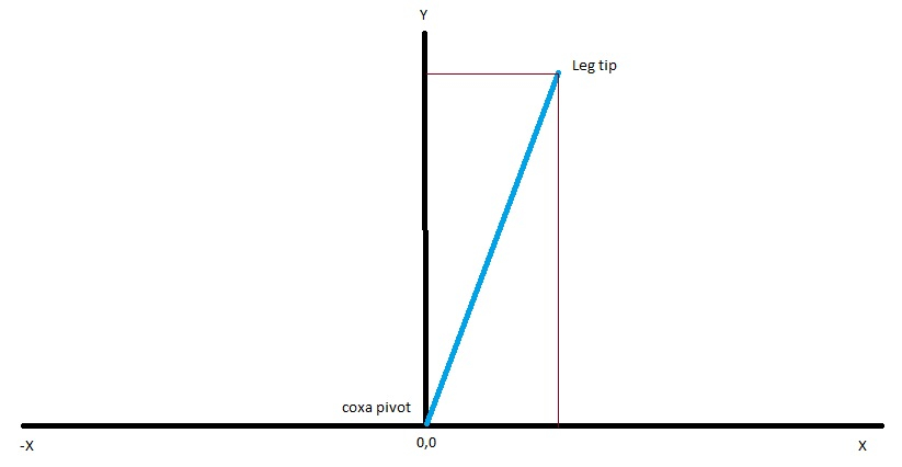
Now we switch from a sideways view of the leg to an overhead view.
The blue line is the line from step7. The angle of the line comes from the coxaAngle input. Y is always a positive value due to the physical properties of the hexapod leg however X can be positive or negative depending on the leg tip position. If the coxaAngle is <90 degrees then X will be negative and positive for all other values. Again qsin() and qcos() are used to get the X and Y values.
Now that I can get the start location, just adding those values to the move calculations will result in the leg moving the correct direction. Now to get back to the coordinate conversion coding.
Getting back to figuring out how to get the hexapod body movement direction I came up with this code tidbit
pub bodyIK() | n, temp
' get body movement values and translate to leg positions
  bodyangle := atan2(bodyy,bodyx)/100
  bodystride := sqrt((bodyx*bodyx)+(bodyy*bodyy))
  debug("Bodyangle: bodyy= ", sdec_(bodyy), " bodyx= ", sdec_(bodyx), "; angle= ", sdec_(bodyangle))
  debug("Bodystride: ", sdec_(bodystride))
  coordinateConversion()
This code figures bodyangle which is the direction the body is moving based on the user input. The user input also determines the bodystride which is the distance each leg travels during a single step
pub coordinateConversion() | n
' convert body movement data to leg coordinates
  repeat n from 1 to 3
    legangle[n] := bodyangle + 900 - fixedlegangle[n]                                     'fixedlegangle[] = 0, 600, 1200 to compensate for leg position around body
    if legangle[n] > 3600                                                                                       'if legangle larger than 360 degrees, get back into allowable range of <180 degrees
      legangle[n] := legangle[n] - 3600
    if legangle[n] > 1800                                                                                       'coxa movement limited to 180 degrees
      legangle[n] := legangle[n] - 1800
    debug("Leg ", sdec_(n), " Angle1: ", sdec_(legangle[n]))
    legXend[n] := (acos(legangle[n] * bodystride) + legXstart[n])
    legYend[n] := (asin(legangle[n] * bodystride) + legYstart[n])
    legangle[n+3] := legangle[n]
    legXend[n+3] := legXend[n]
    legYend[n+3] := legYend[n]
    debug("Leg ", sdec_(n), " Angle: ", sdec_(legangle[n]), " X: ", sdec_(legXend[n]), " Y: ", sdec_(legYend[n]))
This next code, coordinateConversion() converts the bodyangle and bodystride to the individual leg coordinates based on where the leg is located around the body. I only have to do this for leg1, 2, and 3 as the output values are the same for the remaining legs. These 2 routines are in Spin2 but I should write them in PASM2 instead to maximize speed. Of course I really need to learn PASM2 so I've been waiting for a good tutorial before I start that.
Next step is coming up with actual leg movements. I have the initial location of each leg, coordinateConversion() stores the location that the leg tip has to move to. The legIK() routine will output the angles each motor has to move in order to get to a specific X, Y, Z position. However most leg moves directly between the start position and the end position could damage the legs while moving. The solution is to break the movement down into small increments where the leg tip appears to be moving in a straight line between the start and end positions. I have to determine what is a 'safe' movement distance, looking at starting with 1 centimeter increments, and adjust as needed. I have to balance the time it takes for the code to run as each movement increment is sent to the legIK() to get angles, the motors have to actuate to move to the new spot and return completion info back to the P2. Multiply that by 6 legs and you get the issue I ran into using the P1 for these calculations.I only got up to running 2 legs simultaneously before running into calculation delays that caused the legs to 'stutter' as movements would complete and the leg stops while waiting for the next command. Ideally the motion of the leg tip will be smooth.
@DiverBob
I echo your desire to see a tutorial for PASM2. I would also like to see a tutorial on smart pins! A big help to me in moving forword with P2 was JonnyMac's article on the P2 he wrote for Nuts and Volts that he linked in another catagory. It is obvious that you have moved beyond that, but I am still struggling with elementary stuff. I have never had any formal training in coding and my last serious writing was a project written in Z80 ASM (in the mid 80's) that created a 5 part task rotator and time shared the CPU with 5 different serially controlled devices. Wow how much easier that would have been with a P2!
Jim
Started writing code for controlling the gait of the robot. Initially there will only be the tripod gait. This is where there is always 3 legs on the ground. Basically one group of legs is in the air and moving forward for the next step and the legs on ground are pushing the body forward.
Since I don't want the robot to have to actually turn to change direction, I designate a 'front' of the robot based on the requested body angle. This allows the 2 leg groups to be identified for the movement.
pub getFrontLeg() | n
' using bodyangle, determine the 'front' leg, group1 and group2 members are determined by this
' negative group value indicates it is a leading leg so movement increments go opposite of other legs
  case bodyangle
    0..300:     frontleg := 1
                group1[1] := -1
                group1[2] := 3
                group1[3] := 5
                group2[1] := -2
                group2[2] := 4
                group2[3] := -6

    301..900:   frontleg := 2
                group1[1] := -1
                group1[2] := -3
                group1[3] := 5
                group2[1] := -2
                group2[2] := 4
                group2[3] := 6

    901..1500:  frontleg := 3
                group1[1] := 1
                group1[2] := -3
                group1[3] := 5
                group2[1] := -2
                group2[2] := -4
                group2[3] := 6
    1501..2100: frontleg := 4
                group1[1] := 1
                group1[2] := -3
                group1[3] := -5
                group2[1] := 2
                group2[2] := -4
                group2[3] := 6

    2101..2700: frontleg := 5
                group1[1] := 1
                group1[2] := 3
                group1[3] := -5
                group2[1] := 2
                group2[2] := -4
                group2[3] := -6

    2701..3300: frontleg := 6
                group1[1] := -1
                group1[2] := 3
                group1[3] := -5
                group2[1] := 2
                group2[2] := 4
                group2[3] := -6

    3301..3600: frontleg := 1
                group1[1] := -1
                group1[2] := 3
                group1[3] := 5

                group2[1] := -2
                group2[2] := 4
                group2[3] := -6
I'm sure there is a more elegant way to code this but for now this works.
The next routine determines the distance each leg moves in the X and Y direction from its current location to the leg position at the end of the stride. These values are stored for each leg.
pub setupStepIncrement()| n
' divide leg movement into smaller discrete steps
  'initialize
  repeat n from 1 to 6
    xIncrement[n] := (legXend[n] - legXstart[n]) / resolution
    yIncrement[n] := (legYend[n] - legYstart[n]) / resolution
This is the start of the actual gait movement coding, right now all it does is lift the identified front leg, move it to the correct position and lower it. This where the debug commands come in real handy when the leg doesn't move to where it is supposed to, or in my case, it didn't move at all.
First thing I found was a couple of coding errors in the coordinate conversion routine. I used acos when I should have been using qcos, I multiplied the wrong variables together due to misplaced parenthesis, and made an incorrect assumption on which values would not change. Here is the corrected code if you want to compare it to the earlier posted routine.
pub coordinateConversion() | n
' convert body movement data to leg coordinates
  repeat n from 1 to 3
    legangle[n] := bodyangle + 900 - fixedlegangle[n]
    if legangle[n] > 3600
      legangle[n] := legangle[n] - 3600
    if legangle[n] > 1800
      legangle[n] := legangle[n] - 1800
    legangle[n+3] := legangle[n]
  repeat n from 1 to 6
'    debug("Leg ", sdec_(n), " LegAngle: ", sdec_(legangle[n]), sdec(bodystride), sdec(legXactual[n]), sdec(legYactual[n]), sdec(legZactual))
    legXend[n] := ((qcos(10000,legangle[n],3600) * bodystride)/10000) + legXactual[n]
    legYend[n] := ((qsin(10000,legangle[n],3600) * bodystride)/10000) + legYactual[n]
    debug("Leg ", sdec_(n), sdec(legangle[n]), sdec(legXend[n]), sdec(legYend[n]), sdec(legZactual[n]))
Now all that is corrected so now I'm troubleshooting the legIK routine. I am getting invalid angle outputs using valid inputs. So that is where I am tonight, tracking down errors in LegIK code that was previously written for the P1 and converted over to the P2. The error is in the @outbuf string value to leg 3 ($,3,202099,75881,0,1). The value 202099 is the femur angle and 75881 is tibia angle. Coxa angle is 0. Since angle values are limited to a max of 4 integers (example, 108.5 degrees is 1085) and the femur values are outside the permitted limits, so something isn't right anymore. (I wanted to copy from the debug window but can't figure out how to copy and paste from there,)
It took a while running different parameters through the LegIK routine and double checking the results using a calculator but the LegIK is working on the P2
The steps are broken up right now so I could test the math more easily, will come back and try to compact it some once I'm sure its working right.
I started a simple leg movement control by having the P2 raise the 'front leg', move to a specific location and then lower the leg back to the original position. That's when I discovered the Inverse Kinematics code didn't translate well from the P1 to P2 (kind of makes sense now since the P1 was using floating point and I'm using integer math in the P2). Ran into some motor control issues quickly, first the leg tip was moving the wrong direction, forgot that raising the leg tip is like lowering the robot body so instead of subtracting the lift height, the code has to 'add' the lift height. Next problem is the robot was only executing the last set of commands to the leg. Putting some static delays identified that the P2 was doing all the computations, shoving them out and then replacing the movement string with the next string even before the previous move had a chance to start. So only the last movement string actually got executed. Next step was coding in delays using the motor done flags
pub checkMotorDone(leg1, motor) : motordone
' check if motor done flag set for a specific leg
motordone := true
case motor
1: if femurDone[leg1] == 1
motordone := false
2: if tibiaDone[leg1] == 1
motordone := false
3: if coxaDone[leg1] == 1
motordone := false
pub checkAllMotorDone(leg1) : legdone
' check all motors for specified leg have completed movement
legdone := true
if femurDone[leg1] == 1 OR tibiaDone[leg1] == 1 OR coxaDone[leg1] == 1
legdone := false
debug("LegDone: ",sdec(femurDone[leg1]),sdec(tibiaDone[leg1]), sdec(coxaDone[leg1]))
This works but it gets hung up occasionally and the program stalls so that's where I'm at now. Thank you Chip for the DEBUG capabilities in the Prop Tool, this would be much harder to figure out without it! The good thing is that the P2 is actually talking to the P1 leg controllers and receiving feedback data back from the leg controllers. The legs are moving so that is good also. Got to figure out the technique to output the movement commands and not make sure the motors actually have time to respond.
Looks like I have a couple of problems that haven't haven't shown up before. One, the motorDone flag isn't changing on the P2. The input string from the P1 controllers is showing updates to the motor angle data but not the flags. P1 code looks good but I will get back into it and check the output string. The second issue is that the P2 input buffer has valid data for a while and then just goes blank. This is like a problem I had earlier with the multiport serial object that got fixed (need to look back in the postings to see what I did) .
Here is the code for getting feedback from the P1 controller.
obj
strip : "jm_lpd8806" ' * LPD8806 driver
ser : "mpx_fullduplexserial" ' clusos multiport serial driver (based on jonnymacs serial) - suports fdx port
serOut : "mpx_fullduplexserial" ' command output - clusos multiport serial driver (based on jonnymacs serial)
serL1 : "mpx_fullduplexserial" ' Leg 1 - clusos multiport serial driver (based on jonnymacs serial)
serL2 : "mpx_fullduplexserial" ' Leg 2 - clusos multiport serial driver (based on jonnymacs serial)
serL3 : "mpx_fullduplexserial" ' Leg 3 - clusos multiport serial driver (based on jonnymacs serial)
serL4 : "mpx_fullduplexserial" ' Leg 4 - clusos multiport serial driver (based on jonnymacs serial)
serL5 : "mpx_fullduplexserial" ' Leg 5 - clusos multiport serial driver (based on jonnymacs serial)
serL6 : "mpx_fullduplexserial" ' Leg 6 - clusos multiport serial driver (based on jonnymacs serial)
mpxcog : "mpx_multiportserialdriver" ' * multiport serial pasm driver in its' own cog
' * uses cog when loaded
pub setup()
' startup routines for code
cog := mpxcog.start(@port_control) ' start multiport serial pasm driver in new cog
' alternative method to open a port/pin separately...
ser.openport( @port_control, TX_PORT_NUM, TX1, TX_DIRN, MODE, BR_TERM, @TXBUF, @TXBUF + TXBUF_SIZE) ' config tx smartpin and driver for port[n]
ser.openport( @port_control, RX_PORT_NUM, RX1, RX_DIRN, MODE, BR_TERM, @RXBUF, @RXBUF + RXBUF_SIZE) ' config rx smartpin and driver for port[n]
serL1.openport(@port_control, RX2_PORT_NUM, RX2, RX_DIRN, MODE, 57600, @RX2BUF, @RX2BUF + RX2BUF_SIZE) ' config rx smartpin and driver for port[n]
serL2.openport(@port_control, RX3_PORT_NUM, RX3, RX_DIRN, MODE, 57600, @RX3BUF, @RX3BUF + RX3BUF_SIZE) ' config rx smartpin and driver for port[n]
serL3.openport(@port_control, RX4_PORT_NUM, RX4, RX_DIRN, MODE, 57600, @RX4BUF, @RX4BUF + RX4BUF_SIZE) ' config rx smartpin and driver for port[n]
serL4.openport(@port_control, RX5_PORT_NUM, RX5, RX_DIRN, MODE, 57600, @RX5BUF, @RX5BUF + RX5BUF_SIZE) ' config rx smartpin and driver for port[n]
serL5.openport(@port_control, RX6_PORT_NUM, RX6, RX_DIRN, MODE, 57600, @RX6BUF, @RX6BUF + RX6BUF_SIZE) ' config rx smartpin and driver for port[n]
serL6.openport(@port_control, RX7_PORT_NUM, RX7, RX_DIRN, MODE, 57600, @RX7BUF, @RX7BUF + RX7BUF_SIZE) ' config rx smartpin and driver for port[n]
serOut.openport(@port_control,TX2_PORT_NUM, TX2, TX_DIRN, MODE, BR_TERM, @TX2BUF, @TX2BUF + TX2BUF_SIZE) ' config tx smartpin and driver for port[n]
cog := cogspin(NEWCOG, getFeedback(), @p_feedback)
waitms(1000) ' 5s (delay to get PST running)
pub getFeedback() | n, temp
' import position data from leg controllers, load arrays - runs in its own cog continuously
colorinit()
'get feedback string into buffers - seperate buffers due to data dropout
repeat
repeat n from 1 to 6
'retrieve leg feedback string data from individual leg controllers
wordfill(@inputBuf, 0, 400) 'clear buffer
getcmd("$", @inputBuf, 400, n)
if n == 2
debug("P1 inputbuf: ", sdec(n), zstr(@inputBuf))
if inputbuf[0] <> 13
temp := extractfield(1, @inputbuf, ",")
if temp > 100 'this keeps data aligned, otherwise get femurAngle = 100
FemurAngle[n] := temp
FemurDone[n] := extractfield(2, @inputbuf, ",")
fColor[n] := extractfield(3, @inputbuf, ",")
TibiaAngle[n] := extractfield(4, @inputbuf, ",")
TibiaDone[n] := extractfield(5, @inputbuf, ",")
tColor[n] := extractfield(6, @inputbuf, ",")
CoxaAngle[n] := extractfield(7, @inputbuf, ",")
CoxaDone[n] := extractfield(8, @inputbuf, ",")
cColor[n] := extractfield(9, @inputbuf, ",")
LegDownStatus[n] := extractfield(10, @inputbuf, ",")
pub getcmd(hdr, pstr, len, port): result | i, k, char 'routine designed by Jon McPhalen
' get command from serial stream
' hdr is required header character
' pstr is pointer to string space for command
' len is maximum length of input (buffer len-2)
' port (1-6) selects serial object
repeat
case port
1: char := serL1.rxtime(10)
2: char := serL2.rxtime(10)
3: char := serL3.rxtime(10)
4: char := serL4.rxtime(10)
5: char := serL5.rxtime(10)
6: char := serL6.rxtime(10)
if char == -1
result := -1
quit
byte[pstr][0] := (k := char) ' get char from stream
if (k == hdr) ' if header
quit
if result == 0
i := 1 ' set starting index
repeat while (i < len)
case port
1: char := serL1.rxtime(10)
2: char := serL2.rxtime(10)
3: char := serL3.rxtime(10)
4: char := serL4.rxtime(10)
5: char := serL5.rxtime(10)
6: char := serL6.rxtime(10)
if char == -1
quit
byte[pstr][i] := (k := char) ' get char from stream
if (k == 8) ' if backspace
idx := --i #> 1 ' backup
elseif ((k == 0) OR (k == 13)) ' if 0 or CR, quit
quit
else
++i ' advance pointer
byte[pstr][i] := 0 ' terminate string
Couldn't finish the last posting, the website went to dead slow and took a few minutes just to post what I had written.
When I first started using the multi-port object I had issues where it worked great for a while and then would stop working. It acted like a buffer had filled up and wasn't getting refreshed. I never found the cause but I found a work around that at the time seemed to work well. Just running the debug on the inputbuf showed good data coming in for several seconds and then the input string goes blank, no data until I re-compile the program.
As far as the motor done flag goes, it seems the flag update doesn't get sent by the P1 controller. Initial looks at the code show that it is being updated as expected but those changes aren't being picked up and transmitted to the P2 along with the motor angle data. For this problem I need to connect up to the P1 controllers again and run some tests and view the output string to the P2 directly.
I verified the P1 controllers are properly outputting the motorDone flag in the string to the P2. The P2 input routine is not seeing that value when it imports the string. Strangely all the other values are coming in properly and being stored in the right global variables. The P2 input string is formatted like this: "$, femurAngle, femurDone, femurColor, tibiaAngle, tibiaDone, tibiaColor, coxaAngle, coxaDone, coxaColor, legDown". I'm not seeing why all the other values are coming in before and after the motorDone flags and only the motorDone values are not being saved.
In the meantime I realized the motor color values could be be used as a type of motorDone flag also. If the motor color is 'BLACK" then the motor has finished moving. "RED' indicates an error condition and the motor isn't moving their either. So I changed the motorDone routines to check for a motorColor of 'BLACK" or "RED" and ran a test. I found the motors still didn't respond until I put a waitms(100) after the P2 output string to the P1 leg controllers. This delay gave enough time for the motors to actually start moving (I keep forgetting to compensate for the time it takes for a mechanical system to actually start to respond) and the motor color flags to get set.
This doesn't fix the everything but I'm getting better responses so I have to tweak that delay value to ensure the motors have time to get started moving. About time to take a break and listen to todays Parallax Zoom meeting, always a welcome time on a Wednesday!
Continuing with math fun on the P2! Running the legIK routine where the input is an X, Y, Z position and the output is the angles the motors have to go to, I was getting results that were not expected. Using actual leg data I manually ran the calculations on my calculator and found the results weren't matching. First thing was that some leg positions resulted in some parts of the calculation to overflow the 32bit limit. Once that was resolved, I determined that the output angles for the femur were mathematically correct but the leg controller software required the angle to be 180 degrees minus the calculated value. I had done a lot of testing where the femur angle was right around 80-100 degrees so the mistake wasn't as noticeable. Another thing was the LegIK angle output for the tibia was coming up as a small negative number. Finally determined that this was because of rounding from the output of qsin and qcos. The simple fix was to make the tibiaAngle = 0 if it went negative (it was only negative a few tenths of a degree but that threw off all the other calculations later). After running through a wider range of test values and moving the leg to different positions it seems this problem area is fixed.
The next area for math fun is determining the leg X,Y,Z position based on motor angle data, exactly the opposite of the LegIK routine. I've only gotten part way through this routine, first going over the math on paper to make sure I'm using the Law of Cosines properly. I found one big error, the femurAngle value to the leg controllers increases as the leg moves down. However the calculation assumes the angle increases as the leg moves up. TibiaAngle that I use isn't the right angle for the calculation, so looking into that also. So back to the drawing board and map this out on paper so I can code it right.
The bright side is that I was getting the P2 to control multiple leg controllers in a coordinated fashion, too bad the legs weren't going to the right spots yet.
The part discussed earlier about having to subtract the femur Angle from 180 degrees to get the correct angle, something like that got me in a couple of other places in the code also. Consequently the leg was moving quite differently than where I thought it should. To troubleshoot this I had to break out my leg drawing and re-did the geometry, algebra, and trigonometry for the XYPosition routine. The XYposition routine takes the known femurAngle, tibiaAngle, and coxaAngle to get the X and Y position of the leg tip. Going into this, the femurLength, tibiaLength, coxaLength are also known values.
The object is to determine the value of "L" which is the distance from the leg tip to a spot directly under the femur pivot point. To find L there are a couple of steps done first. This uses a simplified diagram of the leg as seen from a side view.
Get angle A - the femurAngle is from the vertical dotted line that goes through the femur pivot point rotating CW down to the solid line representing the femur. There is another vertical dotted line going through the tibia pivot point. From geometry, the line for the femur intersects with parallel vertical dotted lines where the femurAngle at the femur pivot point is the same as the angle on the opposite side of the femur line where it intersect with the other vertical line. The tibiaAngle is represented by the parallelogram so the angle from the tibia pivot to the dotted vertical line is also equal to the tibiaAngle. So angle A = femurAngle + tibiaAngle
With angle A and the lengths of the femur and tibia, the Law of cosines gets the length of the line opposite, 'c'. (I tried to show the actual math but the display doesn't show the various math symbols very well!)
Angle B is also needed in the same triangle, the law of cosines is used again to get this value.
The length 'c' is the hypotenuse of the right triangle formed by the vertical distance bounded by value bodyz and the value 'L' that is needed. To figure this out then angle D is needed, the angle at the top of the right triangle. Get angle D by taking 180 degrees minus the femurAngle and then subtracting angle B from that answer.
This leaves getting the value of 'L' which uses the rules for right triangles where sine of an angle is equal to the opposite side ('L') divided by the hypotenuse ('c'). Rearranging the formula, sin of angle D times the value of 'c' equals 'L'.
Last step using this diagram is adding the coxaLength to 'L' to get the total distance from the coxa pivot point to the leg tip.
The next diagram is an overhead view of a leg with the coxa pivot point being at the intersection of the X and Y plot graph lines. The line heading out from the 0,0 point is at the angle of the coxa as measured from the x axis CCW. The length of the line is the value calculated earlier as the line from the coxa pivot to the leg tip.
1. X value is the sine of coxaAngle multiplied by the line length, Y value is cosine of coaxAngle times the line length.
Once all the angles were figured out and using the Debug feature to capture actual values allowed me to double-check the values independently using a calculator and check they matched. Another item that was a problem was where after each leg move I used the XYPosition routine to update the leg position variables. Problem here is that the mechanical parts don't always move to exactly the same location. So if there was a small movement, sometimes there is a little overshoot but the next command now thinks it has to move back or not move at all. This made for some jerky movements. To fix this I only get the calculated X,Y,Z coordinates right after turning the robot on. From that point all commands are based on where the robot leg is supposed to be. I will have to watch and see if there is any point that the leg position needs to be 'reset' by getting the XYPosition updates, possibly after the robot completes a complete movement sequence and is fully stopped prior to moving again.


Comments
I think my coding notes are getting better, this is the fastest I’ve been able to review the code after a long break and figure out what I had been working on!
Got the red RGB light issue figured out and resolved. This then exposed another unusual light pattern where a white light kept flashing intermittently on each leg. That one was harder to troubleshoot but increasing the buffer size on the P2 communications loop from the leg controllers solved that problem. The feedback data flow from the leg controllers was getting corrupted intermittently also so that was solved by adding code to the input routine to ignore inputs that didn’t have the proper start characters.
I added in the Inverse Kinematics (IK) formulas I developed for the P2 along with trig routines that use integer math instead of Floating Point math in an effort to improve calculation speeds.
Next on the agenda is testing the IK using a single leg and see if I can get it to move in a straight line!
So far there is no danger that the robot will leave the basement on its own!
While testing the individual legs I was getting movements that indicated to me that the legs needed to be re-calibrated. When I would set the femur to 90 degrees the actual angle would be a bit over 100 degrees with similar results on the tibia.
I tried my normal calibration routine and was getting no where, actually the physical angle positions were getting even further away from the expected positions. This morning I really got into the code math behind calculating the angles.
The code first off determines the mathematical slope where the magnetic encoder output at the minimum and maximum angles are compared to the actual degrees the leg is at when at the minimum and maximum mechanical positions. This gives the slope of the line (assumed to be a linear function), or in terms of the program, how many counts of the encoder do you get for each angle change. When a move request is entered, the desired angle is supplied. This is used to calculate the target encoder value based on the slope. The motor is engaged and runs until it gets to the desired position. There is always some over- or under-shoot in this mechanical process so the next step is taking the final encoder value to calculate the actual angle the leg ends up at.
With that information I found that I was using 2 different methods to get the target and the final position values. The difference was in whether I used the minimum or maximum physical angle value. Although mathematically it doesn’t make a difference, in code I was ending up with 2 answers that were close but not close enough.
I fixed the code for the femur so next is fixing the tibia code to match. I’ve always seen small discrepancies but it isn’t until all legs are moving together that it became noticeable that each leg was moving to different positions.
I’ve been working on calibrating the legs which can be a tedious task. I wrote a calibration routine that makes it much simpler now which helps a lot.
I started with leg 1 and worked my way around the robot, taking each leg in order. When I got to leg 3, I found the tibia motor was not responding. After some troubleshooting I removed the leg and put it on the bench for testing the motor. The motor would not turn even with voltage applied directly to the motor leads. So I removed the actuator from the robot and then disassembled the motor. The motor is a 12v brushed motor and I found the brushes were not contacting the rotor commutator. This required removal of the brushes and some filing of the nylon brush holders until the brushes were free to move again. Once the motor was reassembled, power was applied and the motor is working again. It appeared the nylon brush holders got overheated and constricted the brush movement. After this I was able to reattach leg 3 and finish the leg 3 calibration and moved on.
I got to leg 5 and while calibrating the tibia encoder settings, I got a port 3 comm error when I tried to upload to RAM. A reboot and other tests determined the problem is on the Dell Win 10 computer side so have to figure that one out yet. I asked the question in the P1 forum side, hopefully someone has some ideas of how to proceed!
I have seen the melted brush holder issue before and added coding to shutdown the motor controllers if it detects the motor encoder isn’t changing, don’t know if leg 3 is just showing an issue from before the code change or if it is recent. The motor wasn’t hot to the touch and the robot is suspended on the test stand so it wasn’t even supporting its own weight. I did some quick searches on-line for brushless linear actuators but didn’t see anything useful for my situation.
I’m on hold for a bit until I get the Prop Tool to talk to the RoboPi boards again, hopefully it won’t take long to fix
if your motors get hot without load you have a torque/friction problem. How hard is it to move the legs w/o motors attached?
WD40?")
As for the com port try to remove the entry in the device manager, windows does bs there sometimes...
Mike
What I meant was that I checked the motor temperature and it was cool. The legs weren’t touching the ground so there is no load on them. The legs move very easily when the motors aren’t attached, every pivot point has a bearing so there is very little friction on any of the motors. I’m speculating that the heat damage was caused a few months ago when I was still using a P1 as the master and had the full weight on the legs. Due to some of the testing the tibia movements resulted in locked motor rotors on a couple of legs. At that time only one motor failed, this motor may have been damaged and finally got to a failure point. In the meantime I added code to detect locked rotors by monitoring change to the encoder output. If the encoder doesn’t change by more than a value of 5 over 5 cycles of the PID routine, the PID loop is exited. This also accounts for situations where the actuator actuates an internal limit switch and stops.
Thanks for the hint of checking the device manager and reset the com port there. I’ll give it a try next.
Well I am not a EE at all, I learn by burning things and not repeat it again.
One could say that I am a fan of your project. In one of your posts your said 'all legs moving' that is quite a 'step' after just testing them alone.
As for using the P2 as Central controller I think you are right, but I think there is no need to replace all the leg controllers, the P1 can handle that.
This is a very cool project and I hope I can see this thing walking some time.
GO, Bob, GO
Enjoy!
Mike
Got the RoboPi P1 boards to talk to the computer again. Apparently the computer needed a full reboot vs just a restart. Anyway I’ve been able spend a few hours so far calibrating and fixing issues that have shown up. Got all but one fixed, the routine that is supposed to stop the motor if the magnetic encoder value doesn’t change (to prevent locked motor rotor issues and in the event the actuator activates its internal limit switch) is being triggered but the motor continues to run. In this case the motor angle position is 0 degrees and I want it to move to 52 degrees. PST shows the encoder output is not changing so this should stop the motor but the motor then runs until it actuates the actuator limit switch. Good puzzle to figure out!
Walked away from the code for a couple of hours and after coming back fresh, I almost immediately found one error. The tibia code was telling the femur motor to stop instead of the tibia motor! That fixed the issue where the tibia motor continued to run even after being told to stop.
That left the problem where the tibia motor never doesn't start running because the encoder didn't show any motor movement. I determined this only occurs after changing motor direction, a clear indication of mechanical backlash in the linear actuator internal gear train. The fix was to add 50 msec to the PID loop. Since delay this is only necessary when the motor has reversed direction, I added a new flag that is set when the motor direction reverses and 50 msec is only added to the loop during the first loop. That solved both problems found earlier.
One of the other things I have been working on is cleaning up the code to make it more readable and speed the code up. This requires adding more comments which help identify why some parts of the code are in there. I found myself removing some code that wasn't clear only to find out it's purpose later when testing. Not everything is immediately obvious as some code is needed because the computers are interfacing with mechanical systems which don't react as fast as the P1 can process. Good notes help reduce those mistakes!
Busy week, had some computer problems with the Prop Tool that took a bit of work to resolve. After some registry hacking fun, I was able to finally upload the latest code updates into all 6 leg controllers after finishing calibrating all the legs.
Started reviewing my old notes on how to make the legs move using Inverse Kinematics (IK) again. When I've been at this point before I've just used IK to control a single leg, mainly testing routines to allow the leg to move in a straight line. Past issues with getting consistent straight line leg movement is what lead me to adding the magnetic encoders vs the original potentiometers to improve leg position resolution/repeatability. It also put me on the road to create PID-like software in the controllers to get better leg movements vs the earlier motor control coding.
This leads to my current studies, how to get all 6 legs to move in a coordinated method so it can walk. To do that I have to combine each leg's coordinate system into a single coordinate system. The best way to do that is to imagine the center of the body as the 0,0 point of a X,Y grid. By moving the center of the body a given distance and angle, each leg will need to move the same distance and angle. This requires some precision starting measurements of the body to leg distances.
Going back through the CAD files I got the dimensions of the base plate the legs attach to along with the additional distance to the coxa pivot point as the starting point. I decided to start working in millimeters (mm) instead of inches so I can work with whole numbers in the coding, which should make coding easier. So each leg is 250 mm distance away from the body 0,0 coordinate. Using this info and the fact the legs are 60 degrees apart, sine and cosine gave the body coordinates for each leg position.
Next job is determining the formulas to convert a body position into each individual leg coordinate. I've studying some math examples to see how to apply the formulas to my setup. That pretty much brings you up to date with this weeks hexapod work. Hopefully by next week translating body to leg coordinates will be done and I can start coding that in for testing.
As a side note, after finding the issue with the motor brushes melting, did some searching to see if anyone makes affordable brushless linear actuators. So far I haven't found anything I can afford, apparently brushless linear actuators aren't a common item. Of course even if I found them that would entail a lot of work to modify the robot to install along with needing new motor controllers vs the HB-25's I have.... Maybe some day it can be an upgrade!
Good update. Go Bob!
Any new progress Bob?
Jim
Yes, there has been progress but not a lot of time has been spent working on the robot this month, too many other projects around the house and outside needed to be completed before it starts snowing around here.
I believe I figured out the movement requirements and started to write them out here but I realized for it to be really understood I needed some diagrams to go along with the description. I got myself a nice graphics app for my iPad and have drawn up some sketches showing the various angles. Now I need to consolidate all my chicken scratching from several pieces of paper into one coherent description. I figure if I can describe the math process then it makes it much easier to code and even more importantly, much easier to understand what needs to be accomplished further down the line. I hope to get something put together this week and will post it then.
Snow is something that we southern Arizonans go north to visit if we are so inclined. I suspect that being gone all summer has something todo with the honeydo list as well.
Jim
After several days with pencil and paper I realized I was over-thinking how to translate body movement to leg movement. I believe I have a solution and have been checking it out manually using different inputs and my calculator! There are some assumptions used for these calculations:
The ‘front’ of the hexapod is centered on Leg #1. It could be any position but this puts leg 1 at 0º, Leg 2 at 60º and so on for each of the legs when looking at the hexapod from an overhead view. Superimposing a XY grid over this view puts the XY 0,0 intercept point at the center of the hexapod body

Movement of the hexapod is calculated using the center of the body as the starting point. The user determines the direction of movement by inputing an X and Y value. This can be input via a remote joystick using potentiometers which give the appropriate values. Each leg needs to move in the same direction and for the same distance for a step for smooth operation. For this example I am only using the X and Y values of 64mm to determine a direction and stride length.
Get the movement angle. Given the X and Y values, tangent (tan) of the angle is determined.


Tan(angle) = opposite side/adjacent side. This is the direction the body is moving.
Stride length is the hypotenuse of the X and Y values. (Remember Geometry!)
Now we have a direction (45º) and distance (64mm). This based on the center of the hexapod body.
The body center movement is next translated for each leg. Each leg has its own independent coordinate system located around the body center.
The leg has a 180º swing from one side to the other with 90º being the center point for the leg where it is sticking straight out from the body center. The Y axis for the leg is along this line that starts at the coxa pivot point. The X axis is the line along the 0º to 180º point. So X values that are positive are on the >90º side of the line and negative X values are on the <90º side.
In the example, the user requests a 45º movement. Leg 1 is the easiest to calculate as it is in line with the Y axis. If the black dot on the diagram is the current position of the leg tip, then 45º from that location is 90º + 45º, or 135º (leg coordinate goes from 0º to 180º with 90º being in line with the y axis).
The same formula is used to calculate leg 2 and 3 at 75º and 15º respectively. Leg 4, 5, 6 will have the same values as leg1, 2, and 3 so there is no need to calculate them separately. Of course there is always another method available, once you know leg 1 angle then by subtracting 60º from the value, leg 2 and 3 can be figured quickly.

Now that the desired movement angle has been figured out, the distance each leg has to move is needed. The stride length was calculated at 90mm earlier. This is used to get the leg tip position in terms of X and Y for each leg. Leg 1 is the easiest to figure, since it is in the same plane as the user input, the X and Y values are 64mm. Figuring leg 2 requires some math. Leg 2 is at 75º with a stride of 90.
This gives a value of 23mm for the X axis and 87mm for the Y axis for the Leg 2 coordinate system. Leg 3 is calculated the same way based on an angle of 15º. Leg 4, 5, 6 have the same values as legs 1, 2, 3 since the angles are the same.
This gives the amount of movement the leg tip needs to move from its current location. However we also need to know where the leg tip is currently located in the XY coordinate. In this case we need to know the starting X and Y coordinates. Then add the new X and Y values to the start values to get the end point. For the starting coordinates we use the assumed values discussed at the beginning of the discussion. So initially each leg starts at 90º coxa position (X axis value of 0). The tibia angle is 0º so the leg tibia is perpendicular to the ground so the length along the Y axis is equal to the length of the femur plus the distance between the coxa pivot point and the femur pivot point (216mm). All initial leg positions are X=0, Y=216. To get the desired leg tip endpoint, add the initial XY values to the calculated values. For Leg 2, X = Xinitial + Xmovement and Y = Yinitial + Y movement.
Note: There are no negative Y axis values due to the design of the legs where the tibia can not physically move to less than 0º.
Note: X axis is negative on the left side and positive on the right side of the Y axis which is the 90º point. So calculated angles less than 90º require X values to be negative.
X= 0 + -23 = -23mm
Y= 216 + 87 = 303mm
There is one last step to this process. If the robot was just given the end point values to move to, it would not be pretty! The 3 motors on each leg move a slightly different speeds, the distances needed to move are different lengths so the result would be very jerky at best and potentially damaging to the robot legs at worse.
There are lots of ways to make this work but the method I chose is to break the move up into smaller chunks. In this case where the leg is moving 90mm from the initial position to the final position, break it into 5mm sections. So the leg moves 5mm along the path, waits for all motors to finish and then move another 5mm. Repeat this 18 times until the final endpoint is reached. Programmatically there are several ways to approach this, the way I did this initially using the P1 was compare the X and Y values. The larger value is divided by the resolution (5mm) to get the number of steps. The smaller value is divided by the same number of steps. Then a loop is used to increment the X and Y values and the results are run through the IK engine. This ends up being a ‘stairstep’ approach to smoothly move from the start to the endpoint. The resolution value can be changed to improve the smoothness of the leg movement but is limited by the speed of the processor. This is where I found that the P1 floating point math routines were too slow for smooth operation. I suspect the P2 will do much better.
My next step is programming this information into the master P2 computer. Everything on the P2 is done using integer math to speed up the calculation time, I wrote routine for sine, cosine, tan, arcsine, arccosine that does everything in integer math.
Lots of competing interests has impacted my time on the robot but weather in Michigan has definitely turned colder so outdoor activities have been curtailed so back to the hexapod. Coding the previous discussion turned out to be harder than expected! I kept getting errors and results were not what was expected so I finally drew and printed out a scale representation of the overhead view of the hexapod to help visualize the leg movements. From this hard copy I figured out I made some incorrect assumptions in the previous posting.
Physically each leg’s coxa only travels 180º from left to right and the tibia angle can not go less than 0º. The coxa motor is programmed to go to any position between 0º and 180º with 90º being the middle position (leg is sticking straight out from the center of the body). So if I visualize this as a graph of x and y values, the 0º point is on the left side of the x axis, the y axis is at the 90º point and 180º is the far right side of the x axis. So valid angle values have to show up in that range, any angle > 180º has to be converted to fit the 0º to 180º limits.
Since the input angle is determined by the user, it can be anywhere between 0º-360º, this has to be converted to fit each leg and also take into account that each leg is positioned 60º apart. Like earlier, this is based on leg 1 being in the ‘front’ position so the leg’s coxa 0-180º axis is in parallel with the x axis of the body. So the body y axis is 90º for leg 1 coxa.
The calculation becomes taking the body angle, add 90º (account for the 90º offset between the body 0º and leg positions) and subtract the leg position in degrees (leg 1 is 0º, leg 2 is 60º, etc.). So a body angle of 45º becomes 135º for leg 1 and 75º for leg 2.
The first special case is when the calculation results in a value >180º, a location that the leg can not reach. In that case 180º is subtracted from the value to put the angle back into the right axis location of being between 0-180º. For example, a body angle of 120º on leg 1 becomes 120º+90º=210º. Subtracting 180º gives 30º for leg 1. Leg 2 doesn’t have this problem as it is rotated by 60º so the calculation gives an angle of 150º.
The next special case is when the angle calculation is >360º. In this instance 360º is subtracted which gets the angle at the right value. For example, 300º body angle on leg 1 results in 390º, subtracting 360º brings the value back to 30º.
I’ve been manually plugging various body angle values into the formulas and so far the expected values are showing up. Now time put this back into code and run some more tests.
I downloaded the newest version of the PropTool which has built-in floating point for the Prop2 now, no need for a separate library anymore. I’m not aware of any trig function libraries that can use the FP yet, it would be interesting to see how fast this is compared to integer math. Right now I’m committed to doing all my trig/IK functions using integer math but its nice to have options.
Eight inches of in snow in Nashville, so it was indoor stuff also.")
There is so much information in this thread, I believe there is a book in the future. Very impressed with all your calculations and turning them into SPIN code.
While coding the coordinate system conversion routines I realized I was missing some vital information. My drawings assumed the leg tip started at a X=0, Y=0 position and moved from there. Since the legs can't actually go to the XY 0,0 position the actual starting leg tip location is required.
When the hexapod is turned on the leg joint angles are known based on encoder data that is transmitted back to the P2 and is stored under femurAngle[7], tibiaAngle[7], and coxaAngle[7] arrays. What the P2 doesn't know is the actual leg tip position in the X, Y, and Z coordinates as the starting leg position. It took some time and more than a few travels down dead end paths but here is the P2 code. It uses qsin and qcos Spin functions. Since the math is all in integer math it took some time to figure out how to get the correct results but it works. step1 and step2 are constants just to speed things up since those values do not change but the formula is shown above the steps
pub GetXYZLegPosition(n) | f1, t1, c1, step1, step2, step3, step4, step5, step6, step7 'calculate distances using angles in Forward Kinematics 'return leg cartesian location in x,y,z coordinates f1 := femurAngle[n] t1 := 900+tibiaAngle[n] 'put tibia angle in same reference frame as femur angle c1 := coxaAngle[n] 'use law of cosines to get triangle side bounded by femur and tibia '(femurlength * femurlength) + (tibialength * tibialength) step1 := 426329 '2 * femurlength * tibialength step2 := 193040 step3 := sqrt(step1-((step2 * qcos(10000,t1,3600))/10000)) ' use law of cosines to get angle for the above triangle step4 := (23104 + (step3 * step3)) - 403225 step5 := 2 * femurlength * step3 'get angle of right triangle bounded between femur pivot, leg tip and vertical line from pivot to ground step6 := f1 - (acos((step4*1000) / (step5))/100) 'get length of right triangle from leg tip to point below femur pivot and add in coxa distance step7 := ((step3 * qsin(10000,step6,3600))/10000) + coxalength 'Get height from ground to femur pivot legZactual[n] := (step3 * qcos(10000,step6,3600))/10000 ' debug("legZactual: ", sdec_(legZactual[n])) 'switch to coxa overhead to get x,y values in local leg coordinate system if c1 >= 900 legXactual[n] := step7 * qcos(10000,1800-c1,3600)/10000 elseif c1 < 900 legXactual[n] := (step7 * qcos(10000,c1,3600)/10000) * -1 ' debug("legXactual: ", sdec_(legXactual[n])) legYactual[n] := step7 * qsin(10000,c1,3600)/10000 ' debug("legYactual: ", sdec_(legYactual[n])) ' debug("-----------------------------") pub acos(x1) : r | y1, y2, len, angle ' written by Eric R. Smith ' calculate x, y such that the vector from (0,0) to (x,y) ' makes an angle z with the x axis ' input x = cosine value * SCALE ' input: angle in radians as a 1.4 decimal fixed point number ' so a full circle is 2*31416 units y2 := SCALE - ((x1 * x1) / SCALE) y1 := sqrt(y2 * SCALE) len, angle := xypol(x1, y1) r := angle sca FULLCIRCLEThe code has to determine the distance from the coxa pivot point to the leg tip in millimeters. To do that the length of a line (purple) is gotten in step3. Next is getting the angle between that line and the femur, and subtracting that angle from the femurAngle. This gives the top angle of the right triangle that has step3 as the hypotenuse. The length of the distance from the leg tip to the vertical line from the femur pivot point is calculated using qsin() and adding in the coxa length gives the total length from the coxa to the leg tip. That value is used in the next drawing to get the actual X and Y values. Before we go there, the legZActual is calculated using qcos() on the right triangle.
Now we switch from a sideways view of the leg to an overhead view.
The blue line is the line from step7. The angle of the line comes from the coxaAngle input. Y is always a positive value due to the physical properties of the hexapod leg however X can be positive or negative depending on the leg tip position. If the coxaAngle is <90 degrees then X will be negative and positive for all other values. Again qsin() and qcos() are used to get the X and Y values.
Now that I can get the start location, just adding those values to the move calculations will result in the leg moving the correct direction. Now to get back to the coordinate conversion coding.
Super progress Bob!
Getting back to figuring out how to get the hexapod body movement direction I came up with this code tidbit
pub bodyIK() | n, temp ' get body movement values and translate to leg positions bodyangle := atan2(bodyy,bodyx)/100 bodystride := sqrt((bodyx*bodyx)+(bodyy*bodyy)) debug("Bodyangle: bodyy= ", sdec_(bodyy), " bodyx= ", sdec_(bodyx), "; angle= ", sdec_(bodyangle)) debug("Bodystride: ", sdec_(bodystride)) coordinateConversion()This code figures bodyangle which is the direction the body is moving based on the user input. The user input also determines the bodystride which is the distance each leg travels during a single step
pub coordinateConversion() | n ' convert body movement data to leg coordinates repeat n from 1 to 3 legangle[n] := bodyangle + 900 - fixedlegangle[n] 'fixedlegangle[] = 0, 600, 1200 to compensate for leg position around body if legangle[n] > 3600 'if legangle larger than 360 degrees, get back into allowable range of <180 degrees legangle[n] := legangle[n] - 3600 if legangle[n] > 1800 'coxa movement limited to 180 degrees legangle[n] := legangle[n] - 1800 debug("Leg ", sdec_(n), " Angle1: ", sdec_(legangle[n])) legXend[n] := (acos(legangle[n] * bodystride) + legXstart[n]) legYend[n] := (asin(legangle[n] * bodystride) + legYstart[n]) legangle[n+3] := legangle[n] legXend[n+3] := legXend[n] legYend[n+3] := legYend[n] debug("Leg ", sdec_(n), " Angle: ", sdec_(legangle[n]), " X: ", sdec_(legXend[n]), " Y: ", sdec_(legYend[n]))This next code, coordinateConversion() converts the bodyangle and bodystride to the individual leg coordinates based on where the leg is located around the body. I only have to do this for leg1, 2, and 3 as the output values are the same for the remaining legs. These 2 routines are in Spin2 but I should write them in PASM2 instead to maximize speed. Of course I really need to learn PASM2 so I've been waiting for a good tutorial before I start that.
Next step is coming up with actual leg movements. I have the initial location of each leg, coordinateConversion() stores the location that the leg tip has to move to. The legIK() routine will output the angles each motor has to move in order to get to a specific X, Y, Z position. However most leg moves directly between the start position and the end position could damage the legs while moving. The solution is to break the movement down into small increments where the leg tip appears to be moving in a straight line between the start and end positions. I have to determine what is a 'safe' movement distance, looking at starting with 1 centimeter increments, and adjust as needed. I have to balance the time it takes for the code to run as each movement increment is sent to the legIK() to get angles, the motors have to actuate to move to the new spot and return completion info back to the P2. Multiply that by 6 legs and you get the issue I ran into using the P1 for these calculations.I only got up to running 2 legs simultaneously before running into calculation delays that caused the legs to 'stutter' as movements would complete and the leg stops while waiting for the next command. Ideally the motion of the leg tip will be smooth.
@DiverBob
I echo your desire to see a tutorial for PASM2. I would also like to see a tutorial on smart pins! A big help to me in moving forword with P2 was JonnyMac's article on the P2 he wrote for Nuts and Volts that he linked in another catagory. It is obvious that you have moved beyond that, but I am still struggling with elementary stuff. I have never had any formal training in coding and my last serious writing was a project written in Z80 ASM (in the mid 80's) that created a 5 part task rotator and time shared the CPU with 5 different serially controlled devices. Wow how much easier that would have been with a P2!
Jim
Started writing code for controlling the gait of the robot. Initially there will only be the tripod gait. This is where there is always 3 legs on the ground. Basically one group of legs is in the air and moving forward for the next step and the legs on ground are pushing the body forward.
Since I don't want the robot to have to actually turn to change direction, I designate a 'front' of the robot based on the requested body angle. This allows the 2 leg groups to be identified for the movement.
pub getFrontLeg() | n ' using bodyangle, determine the 'front' leg, group1 and group2 members are determined by this ' negative group value indicates it is a leading leg so movement increments go opposite of other legs case bodyangle 0..300: frontleg := 1 group1[1] := -1 group1[2] := 3 group1[3] := 5 group2[1] := -2 group2[2] := 4 group2[3] := -6 301..900: frontleg := 2 group1[1] := -1 group1[2] := -3 group1[3] := 5 group2[1] := -2 group2[2] := 4 group2[3] := 6 901..1500: frontleg := 3 group1[1] := 1 group1[2] := -3 group1[3] := 5 group2[1] := -2 group2[2] := -4 group2[3] := 6 1501..2100: frontleg := 4 group1[1] := 1 group1[2] := -3 group1[3] := -5 group2[1] := 2 group2[2] := -4 group2[3] := 6 2101..2700: frontleg := 5 group1[1] := 1 group1[2] := 3 group1[3] := -5 group2[1] := 2 group2[2] := -4 group2[3] := -6 2701..3300: frontleg := 6 group1[1] := -1 group1[2] := 3 group1[3] := -5 group2[1] := 2 group2[2] := 4 group2[3] := -6 3301..3600: frontleg := 1 group1[1] := -1 group1[2] := 3 group1[3] := 5 group2[1] := -2 group2[2] := 4 group2[3] := -6I'm sure there is a more elegant way to code this but for now this works.
The next routine determines the distance each leg moves in the X and Y direction from its current location to the leg position at the end of the stride. These values are stored for each leg.
pub setupStepIncrement()| n ' divide leg movement into smaller discrete steps 'initialize repeat n from 1 to 6 xIncrement[n] := (legXend[n] - legXstart[n]) / resolution yIncrement[n] := (legYend[n] - legYstart[n]) / resolutionThis is the start of the actual gait movement coding, right now all it does is lift the identified front leg, move it to the correct position and lower it. This where the debug commands come in real handy when the leg doesn't move to where it is supposed to, or in my case, it didn't move at all.
First thing I found was a couple of coding errors in the coordinate conversion routine. I used acos when I should have been using qcos, I multiplied the wrong variables together due to misplaced parenthesis, and made an incorrect assumption on which values would not change. Here is the corrected code if you want to compare it to the earlier posted routine.
pub coordinateConversion() | n ' convert body movement data to leg coordinates repeat n from 1 to 3 legangle[n] := bodyangle + 900 - fixedlegangle[n] if legangle[n] > 3600 legangle[n] := legangle[n] - 3600 if legangle[n] > 1800 legangle[n] := legangle[n] - 1800 legangle[n+3] := legangle[n] repeat n from 1 to 6 ' debug("Leg ", sdec_(n), " LegAngle: ", sdec_(legangle[n]), sdec(bodystride), sdec(legXactual[n]), sdec(legYactual[n]), sdec(legZactual)) legXend[n] := ((qcos(10000,legangle[n],3600) * bodystride)/10000) + legXactual[n] legYend[n] := ((qsin(10000,legangle[n],3600) * bodystride)/10000) + legYactual[n] debug("Leg ", sdec_(n), sdec(legangle[n]), sdec(legXend[n]), sdec(legYend[n]), sdec(legZactual[n]))Now all that is corrected so now I'm troubleshooting the legIK routine. I am getting invalid angle outputs using valid inputs. So that is where I am tonight, tracking down errors in LegIK code that was previously written for the P1 and converted over to the P2. The error is in the @outbuf string value to leg 3 ($,3,202099,75881,0,1). The value 202099 is the femur angle and 75881 is tibia angle. Coxa angle is 0. Since angle values are limited to a max of 4 integers (example, 108.5 degrees is 1085) and the femur values are outside the permitted limits, so something isn't right anymore. (I wanted to copy from the debug window but can't figure out how to copy and paste from there,)
It took a while running different parameters through the LegIK routine and double checking the results using a calculator but the LegIK is working on the P2
pub legIK(x1, y1, z1) | L, L1, c, ikb, ikb1, ikb2, t1, t2, t3
' calculate IK for x, y, z to IKx, IKy, IKz
  debug("---- start legIK ---------")
  debug(sdec(x1), sdec(y1), sdec(z1))
  L1 := sqrt(x1*x1 + y1*y1)
'  debug(sdec(L1))

  L := L1 - coxalength
'  debug(sdec(L))

  c := sqrt(z1*z1 + L*L)
'  debug(sdec(c))

  t1 := (femurLength*femurLength)+(c*c)-(tibiaLength*tibiaLength)
'  debug(sdec(t1))
  t2 := 2*femurLength*c
'  debug(sdec(t2))
  t3 := (t1 * 1000)/t2
'  debug(sdec(t3))
  ikb := acos(t3)/100
'  debug(sdec(ikb))

  ikb2 := acos(z1 * 1000 / c)/100
'  debug(sdec(ikb2))

  t1 := (tibiaLength*tibiaLength)+(c*c)-(femurLength*femurLength)
'  debug(sdec(t1))
  t2 := 2*tibiaLength*c
'  debug(sdec(t2))
  t3 := (t1 * 1000)/t2
'  debug(sdec(t3))
  ikb1 := acos(t3)/100
'  debug(sdec(ikb1))

  femurAngle1 := ikb+ikb2
  tibiaAngle1 := ikb2-ikb1
  coxaAngle1 := atan2(y1, x1)/100
  debug("IK output: ", sdec(femurAngle1), sdec(tibiaAngle1), sdec(coxaAngle1))
The steps are broken up right now so I could test the math more easily, will come back and try to compact it some once I'm sure its working right.
I started a simple leg movement control by having the P2 raise the 'front leg', move to a specific location and then lower the leg back to the original position. That's when I discovered the Inverse Kinematics code didn't translate well from the P1 to P2 (kind of makes sense now since the P1 was using floating point and I'm using integer math in the P2). Ran into some motor control issues quickly, first the leg tip was moving the wrong direction, forgot that raising the leg tip is like lowering the robot body so instead of subtracting the lift height, the code has to 'add' the lift height. Next problem is the robot was only executing the last set of commands to the leg. Putting some static delays identified that the P2 was doing all the computations, shoving them out and then replacing the movement string with the next string even before the previous move had a chance to start. So only the last movement string actually got executed. Next step was coding in delays using the motor done flags
pub checkMotorDone(leg1, motor) : motordone
' check if motor done flag set for a specific leg
  motordone := true
  case motor
    1: if femurDone[leg1] == 1
         motordone := false
    2: if tibiaDone[leg1] == 1
         motordone := false
    3: if coxaDone[leg1] == 1
         motordone := false


pub checkAllMotorDone(leg1) : legdone
' check all motors for specified leg have completed movement
  legdone := true
  if femurDone[leg1] == 1 OR tibiaDone[leg1] == 1 OR coxaDone[leg1] == 1
    legdone := false
  debug("LegDone: ",sdec(femurDone[leg1]),sdec(tibiaDone[leg1]), sdec(coxaDone[leg1]))
This works but it gets hung up occasionally and the program stalls so that's where I'm at now. Thank you Chip for the DEBUG capabilities in the Prop Tool, this would be much harder to figure out without it! The good thing is that the P2 is actually talking to the P1 leg controllers and receiving feedback data back from the leg controllers. The legs are moving so that is good also. Got to figure out the technique to output the movement commands and not make sure the motors actually have time to respond.
Looks like I have a couple of problems that haven't haven't shown up before. One, the motorDone flag isn't changing on the P2. The input string from the P1 controllers is showing updates to the motor angle data but not the flags. P1 code looks good but I will get back into it and check the output string. The second issue is that the P2 input buffer has valid data for a while and then just goes blank. This is like a problem I had earlier with the multiport serial object that got fixed (need to look back in the postings to see what I did) .
Here is the code for getting feedback from the P1 controller.
obj strip : "jm_lpd8806" ' * LPD8806 driver ser : "mpx_fullduplexserial" ' clusos multiport serial driver (based on jonnymacs serial) - suports fdx port serOut : "mpx_fullduplexserial" ' command output - clusos multiport serial driver (based on jonnymacs serial) serL1 : "mpx_fullduplexserial" ' Leg 1 - clusos multiport serial driver (based on jonnymacs serial) serL2 : "mpx_fullduplexserial" ' Leg 2 - clusos multiport serial driver (based on jonnymacs serial) serL3 : "mpx_fullduplexserial" ' Leg 3 - clusos multiport serial driver (based on jonnymacs serial) serL4 : "mpx_fullduplexserial" ' Leg 4 - clusos multiport serial driver (based on jonnymacs serial) serL5 : "mpx_fullduplexserial" ' Leg 5 - clusos multiport serial driver (based on jonnymacs serial) serL6 : "mpx_fullduplexserial" ' Leg 6 - clusos multiport serial driver (based on jonnymacs serial) mpxcog : "mpx_multiportserialdriver" ' * multiport serial pasm driver in its' own cog ' * uses cog when loaded pub setup() ' startup routines for code cog := mpxcog.start(@port_control) ' start multiport serial pasm driver in new cog ' alternative method to open a port/pin separately... ser.openport( @port_control, TX_PORT_NUM, TX1, TX_DIRN, MODE, BR_TERM, @TXBUF, @TXBUF + TXBUF_SIZE) ' config tx smartpin and driver for port[n] ser.openport( @port_control, RX_PORT_NUM, RX1, RX_DIRN, MODE, BR_TERM, @RXBUF, @RXBUF + RXBUF_SIZE) ' config rx smartpin and driver for port[n] serL1.openport(@port_control, RX2_PORT_NUM, RX2, RX_DIRN, MODE, 57600, @RX2BUF, @RX2BUF + RX2BUF_SIZE) ' config rx smartpin and driver for port[n] serL2.openport(@port_control, RX3_PORT_NUM, RX3, RX_DIRN, MODE, 57600, @RX3BUF, @RX3BUF + RX3BUF_SIZE) ' config rx smartpin and driver for port[n] serL3.openport(@port_control, RX4_PORT_NUM, RX4, RX_DIRN, MODE, 57600, @RX4BUF, @RX4BUF + RX4BUF_SIZE) ' config rx smartpin and driver for port[n] serL4.openport(@port_control, RX5_PORT_NUM, RX5, RX_DIRN, MODE, 57600, @RX5BUF, @RX5BUF + RX5BUF_SIZE) ' config rx smartpin and driver for port[n] serL5.openport(@port_control, RX6_PORT_NUM, RX6, RX_DIRN, MODE, 57600, @RX6BUF, @RX6BUF + RX6BUF_SIZE) ' config rx smartpin and driver for port[n] serL6.openport(@port_control, RX7_PORT_NUM, RX7, RX_DIRN, MODE, 57600, @RX7BUF, @RX7BUF + RX7BUF_SIZE) ' config rx smartpin and driver for port[n] serOut.openport(@port_control,TX2_PORT_NUM, TX2, TX_DIRN, MODE, BR_TERM, @TX2BUF, @TX2BUF + TX2BUF_SIZE) ' config tx smartpin and driver for port[n] cog := cogspin(NEWCOG, getFeedback(), @p_feedback) waitms(1000) ' 5s (delay to get PST running) pub getFeedback() | n, temp ' import position data from leg controllers, load arrays - runs in its own cog continuously colorinit() 'get feedback string into buffers - seperate buffers due to data dropout repeat repeat n from 1 to 6 'retrieve leg feedback string data from individual leg controllers wordfill(@inputBuf, 0, 400) 'clear buffer getcmd("$", @inputBuf, 400, n) if n == 2 debug("P1 inputbuf: ", sdec(n), zstr(@inputBuf)) if inputbuf[0] <> 13 temp := extractfield(1, @inputbuf, ",") if temp > 100 'this keeps data aligned, otherwise get femurAngle = 100 FemurAngle[n] := temp FemurDone[n] := extractfield(2, @inputbuf, ",") fColor[n] := extractfield(3, @inputbuf, ",") TibiaAngle[n] := extractfield(4, @inputbuf, ",") TibiaDone[n] := extractfield(5, @inputbuf, ",") tColor[n] := extractfield(6, @inputbuf, ",") CoxaAngle[n] := extractfield(7, @inputbuf, ",") CoxaDone[n] := extractfield(8, @inputbuf, ",") cColor[n] := extractfield(9, @inputbuf, ",") LegDownStatus[n] := extractfield(10, @inputbuf, ",") pub getcmd(hdr, pstr, len, port): result | i, k, char 'routine designed by Jon McPhalen ' get command from serial stream ' hdr is required header character ' pstr is pointer to string space for command ' len is maximum length of input (buffer len-2) ' port (1-6) selects serial object repeat case port 1: char := serL1.rxtime(10) 2: char := serL2.rxtime(10) 3: char := serL3.rxtime(10) 4: char := serL4.rxtime(10) 5: char := serL5.rxtime(10) 6: char := serL6.rxtime(10) if char == -1 result := -1 quit byte[pstr][0] := (k := char) ' get char from stream if (k == hdr) ' if header quit if result == 0 i := 1 ' set starting index repeat while (i < len) case port 1: char := serL1.rxtime(10) 2: char := serL2.rxtime(10) 3: char := serL3.rxtime(10) 4: char := serL4.rxtime(10) 5: char := serL5.rxtime(10) 6: char := serL6.rxtime(10) if char == -1 quit byte[pstr][i] := (k := char) ' get char from stream if (k == 8) ' if backspace idx := --i #> 1 ' backup elseif ((k == 0) OR (k == 13)) ' if 0 or CR, quit quit else ++i ' advance pointer byte[pstr][i] := 0 ' terminate stringCouldn't finish the last posting, the website went to dead slow and took a few minutes just to post what I had written.
When I first started using the multi-port object I had issues where it worked great for a while and then would stop working. It acted like a buffer had filled up and wasn't getting refreshed. I never found the cause but I found a work around that at the time seemed to work well. Just running the debug on the inputbuf showed good data coming in for several seconds and then the input string goes blank, no data until I re-compile the program.
As far as the motor done flag goes, it seems the flag update doesn't get sent by the P1 controller. Initial looks at the code show that it is being updated as expected but those changes aren't being picked up and transmitted to the P2 along with the motor angle data. For this problem I need to connect up to the P1 controllers again and run some tests and view the output string to the P2 directly.
I verified the P1 controllers are properly outputting the motorDone flag in the string to the P2. The P2 input routine is not seeing that value when it imports the string. Strangely all the other values are coming in properly and being stored in the right global variables. The P2 input string is formatted like this: "$, femurAngle, femurDone, femurColor, tibiaAngle, tibiaDone, tibiaColor, coxaAngle, coxaDone, coxaColor, legDown". I'm not seeing why all the other values are coming in before and after the motorDone flags and only the motorDone values are not being saved.
In the meantime I realized the motor color values could be be used as a type of motorDone flag also. If the motor color is 'BLACK" then the motor has finished moving. "RED' indicates an error condition and the motor isn't moving their either. So I changed the motorDone routines to check for a motorColor of 'BLACK" or "RED" and ran a test. I found the motors still didn't respond until I put a waitms(100) after the P2 output string to the P1 leg controllers. This delay gave enough time for the motors to actually start moving (I keep forgetting to compensate for the time it takes for a mechanical system to actually start to respond) and the motor color flags to get set.
This doesn't fix the everything but I'm getting better responses so I have to tweak that delay value to ensure the motors have time to get started moving. About time to take a break and listen to todays Parallax Zoom meeting, always a welcome time on a Wednesday!
Continuing with math fun on the P2! Running the legIK routine where the input is an X, Y, Z position and the output is the angles the motors have to go to, I was getting results that were not expected. Using actual leg data I manually ran the calculations on my calculator and found the results weren't matching. First thing was that some leg positions resulted in some parts of the calculation to overflow the 32bit limit. Once that was resolved, I determined that the output angles for the femur were mathematically correct but the leg controller software required the angle to be 180 degrees minus the calculated value. I had done a lot of testing where the femur angle was right around 80-100 degrees so the mistake wasn't as noticeable. Another thing was the LegIK angle output for the tibia was coming up as a small negative number. Finally determined that this was because of rounding from the output of qsin and qcos. The simple fix was to make the tibiaAngle = 0 if it went negative (it was only negative a few tenths of a degree but that threw off all the other calculations later). After running through a wider range of test values and moving the leg to different positions it seems this problem area is fixed.
The next area for math fun is determining the leg X,Y,Z position based on motor angle data, exactly the opposite of the LegIK routine. I've only gotten part way through this routine, first going over the math on paper to make sure I'm using the Law of Cosines properly. I found one big error, the femurAngle value to the leg controllers increases as the leg moves down. However the calculation assumes the angle increases as the leg moves up. TibiaAngle that I use isn't the right angle for the calculation, so looking into that also. So back to the drawing board and map this out on paper so I can code it right.
The bright side is that I was getting the P2 to control multiple leg controllers in a coordinated fashion, too bad the legs weren't going to the right spots yet.
The part discussed earlier about having to subtract the femur Angle from 180 degrees to get the correct angle, something like that got me in a couple of other places in the code also. Consequently the leg was moving quite differently than where I thought it should. To troubleshoot this I had to break out my leg drawing and re-did the geometry, algebra, and trigonometry for the XYPosition routine. The XYposition routine takes the known femurAngle, tibiaAngle, and coxaAngle to get the X and Y position of the leg tip. Going into this, the femurLength, tibiaLength, coxaLength are also known values.
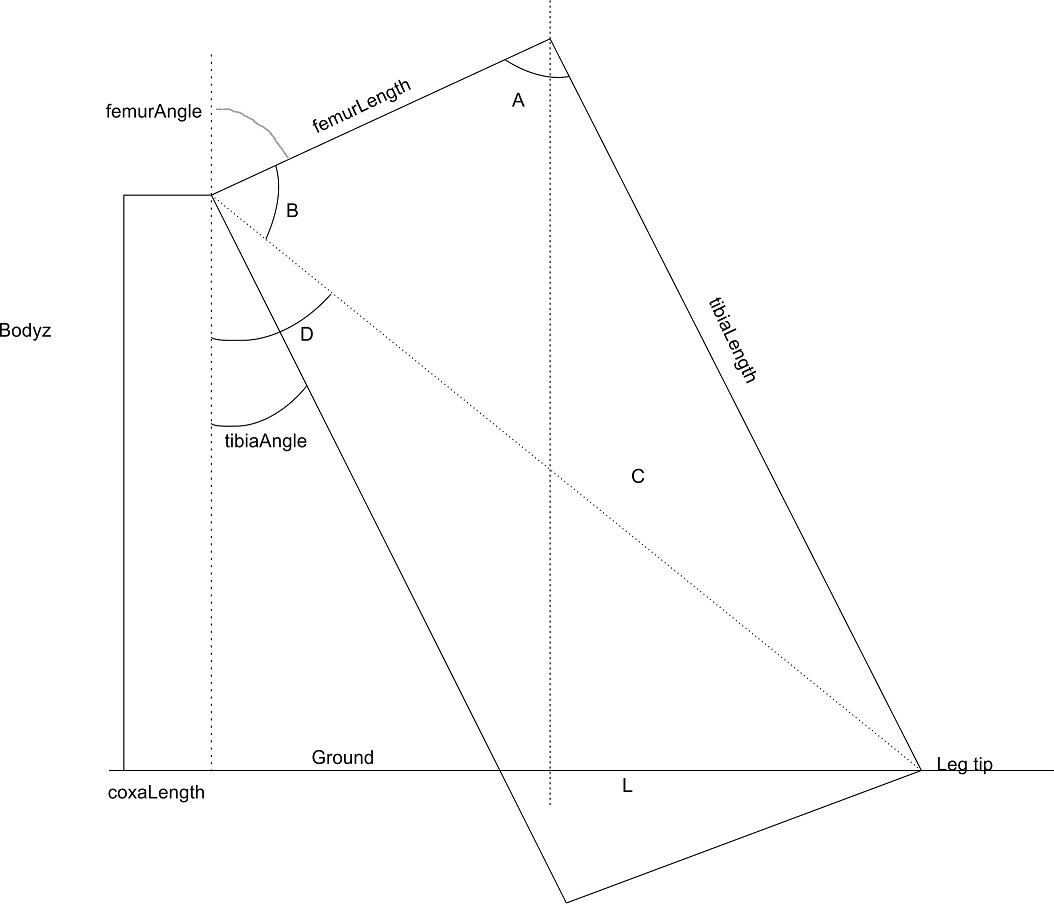
The object is to determine the value of "L" which is the distance from the leg tip to a spot directly under the femur pivot point. To find L there are a couple of steps done first. This uses a simplified diagram of the leg as seen from a side view.
The next diagram is an overhead view of a leg with the coxa pivot point being at the intersection of the X and Y plot graph lines. The line heading out from the 0,0 point is at the angle of the coxa as measured from the x axis CCW. The length of the line is the value calculated earlier as the line from the coxa pivot to the leg tip.
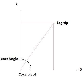
1. X value is the sine of coxaAngle multiplied by the line length, Y value is cosine of coaxAngle times the line length.
Once all the angles were figured out and using the Debug feature to capture actual values allowed me to double-check the values independently using a calculator and check they matched. Another item that was a problem was where after each leg move I used the XYPosition routine to update the leg position variables. Problem here is that the mechanical parts don't always move to exactly the same location. So if there was a small movement, sometimes there is a little overshoot but the next command now thinks it has to move back or not move at all. This made for some jerky movements. To fix this I only get the calculated X,Y,Z coordinates right after turning the robot on. From that point all commands are based on where the robot leg is supposed to be. I will have to watch and see if there is any point that the leg position needs to be 'reset' by getting the XYPosition updates, possibly after the robot completes a complete movement sequence and is fully stopped prior to moving again.
Bob,
In post #542 you mentioned the HH12 encoder using the AS 5045 magnetic encoder. Do you know if they are still available?
Jim
Here is a website that has details about them and who to contact for purchase: http://vk5dj.com/hh-12.html.
Thanks Bob