So 30 decimal is 0x1E which according to the register info above indicates 24 hour mode at 30 hours which seems invalid. I guess footnote 1 applies and it was set incorrectly to begin with, or at power up it gets set with random data or something like that. Hopefully once you write something valid to it it would then fix the issue.
Definitely having a love-hate relationship with the two tiny mosfets...
Want to leave them off, but it's also hard to bridge the tiny gap there.
And, kind of like the idea of reverse voltage and over voltage protection.
Bought a syringe with type 5 solder. Going to see if can use that to force solder through the stencil.
Think the stencil is too thick really for parts like this, but maybe that will work.
@Rayman said:
Ordered PLCC extraction tool from Digikey. Seems one needs that if it is pushed all the way down...
You can't have extracted a real PLCC-84 chip in a long time either. Those are even tighter and require a lot more force to extract than the P2Stamp requires. Extraction tools are a must and even the tips of those will bend on some.
@evanh There seems to be a slight difference between the PCBs that I had made and the original...
The new ones seem to have a thicker plating on the edges that makes it harder to remove than the original.
Or, maybe the PCB itself is a hair wider, not 100% sure.
Just know that the original wasn't so hard to remove when pushed all the way down but the new ones are tighter.
Actually, wait, I don't have the original. I have some made by Screaming Circuits. These are the ones that are looser than the new ones.
Guess I don't actually know how tight the originals are...
Also don't discount something using the Arduino form factor. Just checked and a PLCC84 fits in between header pins rather nicely on a shield so you could make a Propeller based Arduino style board pretty easily using this. The larger mega sized board would offer more IO also. 3.3V from/to 5V is the main issue to deal with but there are wide translation chips available - or one can even use series resistors in a pinch.
True, the cost would be the issue. But convenience is another consideration for some...laying out a P2 board from scratch is non-trivial vs traditional Arduino stuff that beginners often start out with.
@rogloh said:
Also don't discount something using the Arduino form factor. Just checked and a PLCC84 fits in between header pins rather nicely on a shield so you could make a Propeller based Arduino style board pretty easily using this. The larger mega sized board would offer more IO also. 3.3V from/to 5V is the main issue to deal with but there are wide translation chips available - or one can even use series resistors in a pinch.
Ok, that is kind of interesting. But, think need something for me to make sure every I/O is working...
Yeah, the Arduino Mega form factor is probably the better bet, has enough IO for all P2 pins to come out.
@"Christof Eb." and @Rayman I met with our shipping and purchasing staff this morning. We will ship the 6-packs in the ESD Foam boxes (and not overfill these packages, causing bent pins). Order whatever you need [3, 14, 30000) and we will show you the improvement in packaging.
And Rayman, than you for sending the mini P2 module. We showed it last weekend and it is currently on my desk as we design our own version. That was a super considerate gesture from you and we appreciate it.
Any complaints, requests, or ideas - always send them over!
Am thinking about a "Core" version without Flash, HyperRam, and RTC.
This would increase success rate and build rate.
Have three on the bench, one with Flash not working, one with RTC not working, and other with some kind of power problem.
Skipping these components and the baby logic chips that go with them would make this easier.
Plus, would reduce end cost some.
On the fence with uSD. Want to leave it on, since can't really break anything, but just ripped one off the board during extraction from test PCB, so thinking about it...
@knivd had first ones made by a company that went out of business. He suggested JLC. Tried them, but they couldn't figure out how to do the edges...
Then, tried seeed studio. Maybe they could have done it, but wasn't getting a good vibe from them.
Finally, tried Gold Pheonix PCB. Had a feeling they could do it because they do all kinds of strange things.
They did it, but was ~$14 each at Qty.50.
So, was actually hoping that you all could find a place to make them cheaper...
Thinking JLC could do it, if could be explained better...
They seemed to think that all the pins on an edge would be shorted out by the plating.
But, that's only if the plating goes up too far on the edge...
Should also say that @knivd had a plan to make the edge flat, see attached pic.
He gave me gerbers and tried those with JLC too, but no luck...
That's still an interesting idea though...
Actually, should mention that whatever PCB fab Screaming Circuits uses also made boards that worked.
But, those are made in USA, meaning probably cost a fortune.
Fully populated modules were $400 each at Qty. 10.
Actually, guess don't really know where the PCBs where fabbed. Was assuming USA, but that might not be true...
@Rayman said:
Should also say that @knivd had a plan to make the edge flat, see attached pic.
He gave me gerbers and tried those with JLC too, but no luck...
That's still an interesting idea though...
The socket design would make a true flat edge very difficult, as the plastic fingers are designed to go between the PLCC pins.
Some scalloping would be needed
@Rayman said:
Was curious as to how secure the P2Stamp was going to be in its PLCC-84 socket...
Turns out it's a bit too secure. If you push it all the way down, it's very hard to extract.
Was bending metal on every tool was trying...
Ordered PLCC extraction tool from Digikey. Seems one needs that if it is pushed all the way down...
Good extraction will be quite challenge. We've found PLCC socket corners can collapse, as well as IC packages get nibbled into, and that effect is likely worse on FR4 PCB.
The thru hole PLCC sockets have inner large holes, that could be used with a push-tool, but I've not seen any SMD sockets with those holes.
You can't remove the inner web, as that provides tension for the pin springs.
I recall on one project we made a PLCC44 MCU with an araldite-attached handle, that actually worked very well, for initial board testing.
Would there be room for solder holes in two corners ?


Comments
So 30 decimal is 0x1E which according to the register info above indicates 24 hour mode at 30 hours which seems invalid. I guess footnote 1 applies and it was set incorrectly to begin with, or at power up it gets set with random data or something like that. Hopefully once you write something valid to it it would then fix the issue.
The RTC registers are BCD so the test code is displaying them as 2-digit hex.
I think you're correct about writing valid values to the registers to get things going.
Got 4 made this weekend. That's a 400X improvement over last week!")
Still, not where needs to be...
Getting some things sorted out along the way though. Should be better next time...
Need to get the feeders working...
Definitely having a love-hate relationship with the two tiny mosfets...
Want to leave them off, but it's also hard to bridge the tiny gap there.
And, kind of like the idea of reverse voltage and over voltage protection.
Bought a syringe with type 5 solder. Going to see if can use that to force solder through the stencil.
Think the stencil is too thick really for parts like this, but maybe that will work.
If not, guess stuck using air gun to fix them...
Was curious as to how secure the P2Stamp was going to be in its PLCC-84 socket...
Turns out it's a bit too secure. If you push it all the way down, it's very hard to extract.
Was bending metal on every tool was trying...
Ordered PLCC extraction tool from Digikey. Seems one needs that if it is pushed all the way down...
You can't have extracted a real PLCC-84 chip in a long time either. Those are even tighter and require a lot more force to extract than the P2Stamp requires. Extraction tools are a must and even the tips of those will bend on some.
@evanh There seems to be a slight difference between the PCBs that I had made and the original...
The new ones seem to have a thicker plating on the edges that makes it harder to remove than the original.
Or, maybe the PCB itself is a hair wider, not 100% sure.
Just know that the original wasn't so hard to remove when pushed all the way down but the new ones are tighter.
Actually, wait, I don't have the original. I have some made by Screaming Circuits. These are the ones that are looser than the new ones.
Guess I don't actually know how tight the originals are...
Here's latest idea for a breakout for P2Stamp...
Also don't discount something using the Arduino form factor. Just checked and a PLCC84 fits in between header pins rather nicely on a shield so you could make a Propeller based Arduino style board pretty easily using this. The larger mega sized board would offer more IO also. 3.3V from/to 5V is the main issue to deal with but there are wide translation chips available - or one can even use series resistors in a pinch.
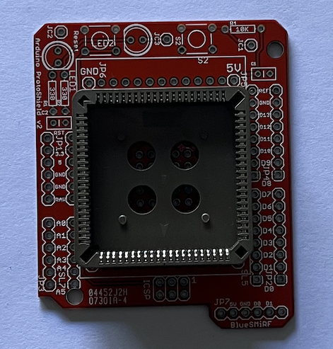
Unless the P2Stamp somehow gets cheap to make, it'd be far better to do a Prop2 design specifically as an Arduino form factor.
True, the cost would be the issue. But convenience is another consideration for some...laying out a P2 board from scratch is non-trivial vs traditional Arduino stuff that beginners often start out with.
The idea here is really about being able to test all the P2 pins in an easy way and also for something useful and cheap
Have a few P2 Stamp modules made, but feel like shouldn't sell them without some kind of basic board to house them...
Or, is there something not seeing?
Ok, that is kind of interesting. But, think need something for me to make sure every I/O is working...
Yeah, the Arduino Mega form factor is probably the better bet, has enough IO for all P2 pins to come out.
Arduino mega form factor is interesting for other reasons. Have to look at that too…
Thinking about getting this solder pot to help with these breakout boards.
Not happy with P2 chips directly from Parallax…. They put 10 in a little box that can maybe fit 6. So several of them wound up with bent pins .
They are a lot cheaper than from digikey or mouser though …
Guess will try ordering just 6 at a time and see how that goes.
The digikey ones come in a nice plastic tray that totally protects the pins when order qty is 10 or so. Maybe that is why they cost more…
That's no go in my opinion.
What do You think, @"Ken Gracey" ?
@"Christof Eb." and @Rayman I met with our shipping and purchasing staff this morning. We will ship the 6-packs in the ESD Foam boxes (and not overfill these packages, causing bent pins). Order whatever you need [3, 14, 30000) and we will show you the improvement in packaging.
And Rayman, than you for sending the mini P2 module. We showed it last weekend and it is currently on my desk as we design our own version. That was a super considerate gesture from you and we appreciate it.
Any complaints, requests, or ideas - always send them over!
Ken Gracey
Thanks Ken!
I do appreciate the much lower price ordering directly from Parallax.
Glad to hear issue is resolved.
Sales tells me they come in a Qty 90 tray. Thinking about that…. Extra discount at Qty. 90…
Am thinking about a "Core" version without Flash, HyperRam, and RTC.
This would increase success rate and build rate.
Have three on the bench, one with Flash not working, one with RTC not working, and other with some kind of power problem.
Skipping these components and the baby logic chips that go with them would make this easier.
Plus, would reduce end cost some.
On the fence with uSD. Want to leave it on, since can't really break anything, but just ripped one off the board during extraction from test PCB, so thinking about it...
Ray, could you please help us by pointing us to a vendor than can build these projected-pin PCBs? You did a great job on this!
@cgracey Sure, here's the story:
@knivd had first ones made by a company that went out of business. He suggested JLC. Tried them, but they couldn't figure out how to do the edges...
Then, tried seeed studio. Maybe they could have done it, but wasn't getting a good vibe from them.
Finally, tried Gold Pheonix PCB. Had a feeling they could do it because they do all kinds of strange things.
They did it, but was ~$14 each at Qty.50.
So, was actually hoping that you all could find a place to make them cheaper...
Thinking JLC could do it, if could be explained better...
They seemed to think that all the pins on an edge would be shorted out by the plating.
But, that's only if the plating goes up too far on the edge...
Should also say that @knivd had a plan to make the edge flat, see attached pic.
He gave me gerbers and tried those with JLC too, but no luck...
That's still an interesting idea though...
BTW: I'm asking @knivd about a P1 version, maybe with an I/O expander on same package. Sounds like he might do it, if ever has free time...
Although, another idea might be to use smaller PLCC for P1...
Or maybe 2X P1? Wish that QFN version was still around... That might fit...
Actually, should mention that whatever PCB fab Screaming Circuits uses also made boards that worked.
But, those are made in USA, meaning probably cost a fortune.
Fully populated modules were $400 each at Qty. 10.
Actually, guess don't really know where the PCBs where fabbed. Was assuming USA, but that might not be true...
The socket design would make a true flat edge very difficult, as the plastic fingers are designed to go between the PLCC pins.
Some scalloping would be needed
Good extraction will be quite challenge. We've found PLCC socket corners can collapse, as well as IC packages get nibbled into, and that effect is likely worse on FR4 PCB.
The thru hole PLCC sockets have inner large holes, that could be used with a push-tool, but I've not seen any SMD sockets with those holes.
You can't remove the inner web, as that provides tension for the pin springs.
I recall on one project we made a PLCC44 MCU with an araldite-attached handle, that actually worked very well, for initial board testing.
Would there be room for solder holes in two corners ?
Holes under the socket to aid in extraction is a great idea! Thanks @jmg
The smd socket has giant holes as I recall