Well, it took the greater part of today, but got the top of first P2 Stamp assembled.
First issue was had no way to hold Stamp in place for applying solder with the stencil.
Had to design and print this orange holder for it.
Then, the solder paste was too coarse to go through the smaller than 0402 pads on some of these parts. Some of the 0402 looked like they didn't have enough paste as well.
Have to get some finer paste...
The part placement process went well enough though.
But, using air gun to place the missing parts took forever. This 8 layer board takes forever to heat up and can't use much air speed on tiny parts.
Was major pain, but top might be OK now.
Now printing out a new holder so can apply paste to the bottom.
Hoping to test it out tomorrow...
Was the Hyperram chip pulling down the 3.3 V bus...
That was #1 suspect because it moved during reflow and had to be reworked back into position...
Can get that fixed, no problem.
Power filter mosfets are a bigger problem. Still thinking about replacing them with a zero Ohm chip resistor...
But, maybe I'll try again to get them connected... Then, won't need the 5V jumper wire...
@evanh said:
Actually, for pick'n'place ability, would it be possible to have a hand-filled tray of components? So then no need for feeders there either.
Yeah, the feeders are not working for me at the moment. Either doing something wrong, or there's a hardware issue. Been meaning to check the servo voltage.
Also, white tape in a white feeder seems to mess with vision finding sprocket holes.
So, for now, using "strip" feeders and "tray" feeders. These both work nearly perfectly.
I guess it could be right... The mosfet can take VGS of >9V and the power regulator allows for up to 20V input.
So, suppose it's OK. Think it should actually work without the zener with 5V applied.
No idea why can't get this to work. Must be the mosfets aren't actually making contact...
I'm suspicious that there's a hardware issue. Asked @knivd about it and he doesn't have code to test it...
Circuit diagram looks OK though, so don't know...
One of my habits when developing a new device is to write "disposable" test code that doesn't tend to rely on libraries. Yeah, this can seem wasteful, but I find that I can focus on the device when not worried if a library is functioning properly. Luckily, the SPI interface to that device is really simple and the buffers allow P57 to act like a normal (i.e., active-low) chip select.
I knocked together this quick bit-banged SPI routine (I need PASM2 practice, so I used this as an excuse to do it inline).
con

  HCLK = (CLK_FREQ / 1_000_000) >> 1                            ' half clock at ~1MHz


pub transfer(outbyte) : result | i

  org
                        mov     i, #7                           ' MSB
.loop                   testb   outbyte, i              wc
                        drvc    #RTC_SDO
                        waitx   #HCLK
                        drvh    #RTC_SCK
                        waitx   #HCLK
                        drvl    #RTC_SCK
                        nop
                        testp   #RTC_SDI                wc
                        bitc    result, i
                        djnf    i, #.loop

                        drvl    #RTC_SDO                        ' leave MOSI low
  end
And here's the capture on a cheap logic analyzer.
Of course, I don't have a device so there's nothing happening on the RTC_SDI pin -- though I'm not sure why it's high.
You code seemed to be missing main code, so added this for testing:
Yeah, I was just trying to give you a tool that might be helpful. BTW, the actual seconds register is on on page 1, so this should give you running time output:
t := getct()
repeat
rtc_read(1, 0, 3, @scs)
term.fstr3(@"The time is %.2x:%.2x:%.2x\r", hrs, mns, scs)
waitct(t += CLK_FREQ)
I probably should have included that in my demo. Anyway, glad you're making progress.
The time is 30:01:37
The time is 30:01:38
The time is 30:01:39
The time is 30:01:40
The time is 30:01:41
The time is 30:01:42
The time is 30:01:43
Do see an error on my part with the CE signal. Seems chip itself is not inverted, but there's a logic inverting chip in between P2 and RTC. Wasn't really clear in schematic, but should have know from the parts.
Still, tried CE both ways, and doesn't work either way. Guess need scope or logic analyzer to figure that one out...
TBH, I didn't notice because I didn't look closely -- I downloaded the datasheet and when I saw it used an active-high enable, looked at the buffers to see what was happening with them.
Just checked flash on new Stamp using this code.
So are the hours behaving now? I wish RTCs would just operate in 24-hour mode and let the application decide how to deal with them. This is from the docs, and I couldn't sort out what $30 is.


Comments
Well, it took the greater part of today, but got the top of first P2 Stamp assembled.
First issue was had no way to hold Stamp in place for applying solder with the stencil.
Had to design and print this orange holder for it.
Then, the solder paste was too coarse to go through the smaller than 0402 pads on some of these parts. Some of the 0402 looked like they didn't have enough paste as well.
Have to get some finer paste...
The part placement process went well enough though.
But, using air gun to place the missing parts took forever. This 8 layer board takes forever to heat up and can't use much air speed on tiny parts.
Was major pain, but top might be OK now.
Now printing out a new holder so can apply paste to the bottom.
Hoping to test it out tomorrow...
Still looks semi-decent for all the trouble you went through. A fine effort so far for making it yourself.
Hope it tests out nicely and boots up okay without too many dramas.
What would it take to turn the pick'n'place machine into a paste applicator? Don't need lots of feeders for that.
Actually, for pick'n'place ability, would it be possible to have a hand-filled tray of components? So then no need for feeders there either.
Starting to think should have done the bottom side first...
Not exactly sure how to reflow bottom without messing up top...
Guess going to try hot air gun on it...
Part count is actually higher on bottom side…
Air gun worked on it and looks good.
Microscopic Mosfets aren’t working but can just jumper over them. Might just remove this power protection circuit…
1.8 vdc supply works but something is dragging down 3.3 vdc. Guess going to just remove things until it works.
There were a couple part rotation errors that had the P2 crystal XO shorted to ground. Hopefully that didn’t break the P2 but maybe it did…
Prop2 can boot on RCFAST without a crystal. In fact I think XO is floating at power up. RCFAST and reset/booting still needs the 3v3 supply though.
PS: And 600 ohm drive is pretty weak too. It wouldn't harmed even it was shorted.
P2 Stamp has a pulse!
Was the Hyperram chip pulling down the 3.3 V bus...
That was #1 suspect because it moved during reflow and had to be reworked back into position...
Can get that fixed, no problem.
Power filter mosfets are a bigger problem. Still thinking about replacing them with a zero Ohm chip resistor...
But, maybe I'll try again to get them connected... Then, won't need the 5V jumper wire...
BGAs suck!
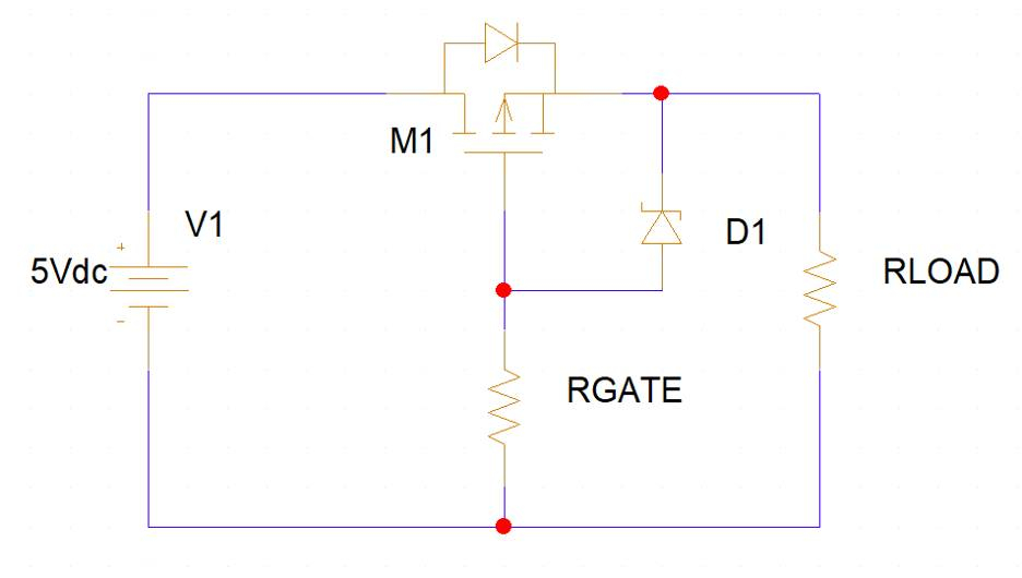
I wouldn't call those filtering transistors, they're used as low loss reverse protection. The current is low, just stick in a Schottky diode.
Yeah, the feeders are not working for me at the moment. Either doing something wrong, or there's a hardware issue. Been meaning to check the servo voltage.
Also, white tape in a white feeder seems to mess with vision finding sprocket holes.
So, for now, using "strip" feeders and "tray" feeders. These both work nearly perfectly.
Ha! Cool, shows I've never seen one in action.
Still can't get the reverse voltage protection circuit to work...
Starting to think the wrong zener diode is spec'd..
The BOM says: 112-BZX884B9V1L-G3-08CT-ND
But, this is a 9.1 V zener.
Can that be right?
I guess it could be right... The mosfet can take VGS of >9V and the power regulator allows for up to 20V input.
So, suppose it's OK. Think it should actually work without the zener with 5V applied.
No idea why can't get this to work. Must be the mosfets aren't actually making contact...
Got it! Pushed down on the mosfets while under air gun and now it works.
Hopefully, the new T5 solder paste will spare me this misery, or I'm just going to bypass this protection circuit...
Here's a decent explanation of how the protection circuit works:
https://resources.pcb.cadence.com/blog/simple-solutions-for-reverse-polarity-protection
The P2Stamp schematic I've got doesn't have the zenor but it's clearly a good thing. Thanks for the link.
Yes, 9 Volts is suitable gate limit. It'll be a "logic level" MOSFET, making 5 Volt turn it fully on.
Tried to get the RTC talking yesterday without any luck.
Anybody get the RTC working with their P2 Stamp from @knivd ?
Haven't tried it myself. Do you have an original Knivd built P2Stamp? I have one if you need me to try anything.
If you do some code to get the RTC talking, would be great.
I don't have an @knivd one, but have a few that had made. Also, the one just made at home...
Can't figure out RTC on either type...
Have you tried an I2C scanner to see if the RTC responds at all?
It's a strange one because wired as SPI. But, seems you can tie MOSI to MISO and then it would be like I2C, I guess...
@JonnyMac Was using your spi driver, but doing something wrong....
What is the part # for the RTC?
RV-3149-C3
https://www.microcrystal.com/fileadmin/Media/Products/RTC/App.Manual/RV-3149-C3_App-Manual.pdf
I'm suspicious that there's a hardware issue. Asked @knivd about it and he doesn't have code to test it...
Circuit diagram looks OK though, so don't know...
One of my habits when developing a new device is to write "disposable" test code that doesn't tend to rely on libraries. Yeah, this can seem wasteful, but I find that I can focus on the device when not worried if a library is functioning properly. Luckily, the SPI interface to that device is really simple and the buffers allow P57 to act like a normal (i.e., active-low) chip select.
I knocked together this quick bit-banged SPI routine (I need PASM2 practice, so I used this as an excuse to do it inline).
con HCLK = (CLK_FREQ / 1_000_000) >> 1 ' half clock at ~1MHz pub transfer(outbyte) : result | i org mov i, #7 ' MSB .loop testb outbyte, i wc drvc #RTC_SDO waitx #HCLK drvh #RTC_SCK waitx #HCLK drvl #RTC_SCK nop testp #RTC_SDI wc bitc result, i djnf i, #.loop drvl #RTC_SDO ' leave MOSI low endAnd here's the capture on a cheap logic analyzer.
Of course, I don't have a device so there's nothing happening on the RTC_SDI pin -- though I'm not sure why it's high.
@JonnyMac Think you might have something...
On the modules that were bought, get this from the RTC:
which is infinitely better than all zeros was getting.
You code seemed to be missing main code, so added this for testing:
pub main() | x setup() wait_for_terminal(true, 250) repeat ' forever rtc_read(0,0,6,@scs) repeat x from 0 to 9 term.dec(byte[@scs+x]) term.tx(13) waitms(1000) term.tx(13)Have to fix a wrong rotation tiny logic chip on the new one before it will work...
New board now fixed and giving same output as above.
Seems you have to enable the chip after a power cycling...
Yeah, I was just trying to give you a tool that might be helpful. BTW, the actual seconds register is on on page 1, so this should give you running time output:
  t := getct()
  repeat
    rtc_read(1, 0, 3, @scs)
    term.fstr3(@"The time is %.2x:%.2x:%.2x\r", hrs, mns, scs)
    waitct(t += CLK_FREQ)
I probably should have included that in my demo. Anyway, glad you're making progress.
Yep, that seems to work, but hours appears wrong?
Do see an error on my part with the CE signal. Seems chip itself is not inverted, but there's a logic inverting chip in between P2 and RTC. Wasn't really clear in schematic, but should have know from the parts.
Still, tried CE both ways, and doesn't work either way. Guess need scope or logic analyzer to figure that one out...
I do like how the Spin2 bitfield thing helps here. Very nice in this case...
Just checked flash on new Stamp using this code. It works! Guess there's only hyperram and uSD left to check on...
TBH, I didn't notice because I didn't look closely -- I downloaded the datasheet and when I saw it used an active-high enable, looked at the buffers to see what was happening with them.
So are the hours behaving now? I wish RTCs would just operate in 24-hour mode and let the application decide how to deal with them. This is from the docs, and I couldn't sort out what $30 is.