Bit cold, dude. My .sig expresses how I feel about this thread.
Was referring to coordinated motion control.
Motors setting off at different times cannot be considered coordinated....pussy-footing around with factual information doesn't help anyone.
I’ve been working on simplifying testing routines as often I find a problem, go and fix the issue, probably make more changes, and then need to test everything so I can get back to the point I was at before. I end up not testing everything consistently which means some issues only appear to be fixed and come back later. I was writing testing code on the fly for each problem, not good. What I need is a consistent set of test routines so I identified several test situations to test each time I make code changes.
The test routines check feedback from the P1 motor controllers, communications from the P2 to the P1’s and the HB-25 motor controllers, check leg ability to move to specific positions via angle inputs, check leg constraints, check the Inverse Kinematics math, physically move both single and groups of legs, and check IK operation. This set of tests should ensure the base code is in good shape before moving on to new stuff.
I haven’t gotten all of these tests programmed in yet (still debugging the tests!) but I put together a short video of the existing test routines, the resulting leg movements, and the debugging capabilities using Chip’s Debugger and the RGB light show on the hexapod. Hope you like it!
[
I didn’t show all the existing tests in the video, as I was filming you see that I found some math issues, some instances where a leg didn’t actually move to a position, and a handful of other errors that need to be tracked down. I troubleshoot and fix problems by creating a checklist of the problem, list any initial conditions (leg start/end position), and what test identified the issue. This way I can later re-run that test specifically to make sure the problem was corrected using the same conditions that created the problem.
I’m in the unique position of troubleshooting my troubleshooting code….
As I try to narrow down and isolate issues to correct, I noticed something. I was getting a lot of error messages from the P1 controllers about, ‘Encoder not responding’. This particular error came about a while back when a leg would come up against an immovable object (another leg or the software position limits failed), so the motor is trying to move the leg but the leg physically can not move. That’s when motors fuses would blow or the motor overheats and damages the motor brushes. The answer to this condition is to compare the encoder reading to the previous 5 encoder readings as the motor is in its PID loop. 5 times around the PID loop without the encoder changing implies there is a problem so I shutdown the motor, exit the PID loop and export the error. During manual testing on the P1 controller I rarely get this error except when I purposefully block movement.
But now when testing using the P2 master, I’m getting this error often. Thinking it through, the biggest difference is that when manually testing, during each PID loop there are several troubleshooting print commands being sent to the PST that are not active when running via the P2. So I’m suspecting the printing code is introducing a delay that allows extra time for the affected motor to start up, take up any gear backlash, and start to physically move the axis which shows up on the encoder. If true, then when running from the P2, the motors are starting but there isn’t enough time for the physical aspect of the movement to get detected by the encoder before it throws an error.
So, how to fix it? I could measure the actual time the print statements take and use that value as a loop delay. Another option is to increase the number of PID loop cycles before evoking this error (instead of 5 loops, go for 10 non-moving encoder values).
Another related issue I noticed when I did the last video, 2 legs got the encoder error and did not move the femur while the other 4 legs did move the requested position. The right thing to do is to stop all leg movements if any leg is not moving as requested. But what about a situation where a move request happens and the move is just outside the motor’s PID deadband (dead band is set for 5 ticks of the encoder or about 0.44º movement). So if the error value is 6, then the move amount is 0.088º. The PID may not wind up enough to cause the motor to actually start moving (due to very low starting error value) before the encoder not moving error triggers. In this case the fact the one leg didn’t move a degree or two may not be an issue. Maybe I need to break the encoder error into 2 levels, small and large. Small errors could be tolerated but above a given value it requires all legs to stop.
Interesting paper and video. I took a quick look at the C++ code, I’m not a C programmer so it will take some time to digest it all. I like it has a MIT license, could be fun to put together a demo and see what it can do.> @Mickster said:
IF PID_Output > Torque_Limit then PID_Output = Torque_Limit
A stalled axis causes the PID_Ouput to increase rapidly (aka: Following Error)
Craig
I don’t have any means to measure torque output of the motors at this time. At one time I was looking at how to measure motor current but those sensors were out of my budget (since I would need 18 of them!) and I had run out of cogs to act on the data.
I do something along that line, by constraining the PID output (limit PID error based on experimental testing to limit output overshoot and still have fast initial response). There are also constraints on the servo output to the HB-25 motor controllers (1000-1500 msec for movement one direction and 1500-2000 msec for movement the other direction). The PID loop operates fairly quickly and the linear actuators have lots of internal gearing and then the output shaft is turning a captured nut that gives the linear output. I’m becoming more convinced the mechanical delay from the time the motor and gears start to move, which turns into linear movement of the output shaft and that process causes the affected axis to start to rotate, which is finally picked up by the magnetic encoder. I’d rather not put any ‘delays’ in the PID loop, so will be testing increasing the time frame the encoder not changing routine looks for non-changing values.
I am finding that I only get this encoder error on the femur and tibia, both use linear actuators. The coxa is a geared motor that drives a custom gear train and rarely gets an encoder error.
Hi @DiverBob
if you don't like the following, just forget it and sorry. But perhaps you can take something from it? Reasons to write this: I have seen your video now and the motions seem to be relatively slow, but on the other hand you seem to be struggling about control of movements for months now.
I have done some projects now with the propellers and some of them include motion control.
For me it seems, that your system with 6P1 + 1P2 brings very much to much complexity for this project. P2 should be capable of doing this task (control 18 slow axis) with only some primitive means to have more pins. How many FAST pins do you need for each axis? One counter input and one PWM output? At least I would degrade the P1s to very simple in/out chips and to concentrate all development work to the P2. I also think, it would be helpful to take out the P1s and if it is really necessary to have more controllers, use less P2s instead. The reason is, that there are so many differences between P1 and P2.
My experience is, that it is only of benefit, to split tasks, if they are really rather independent. If they are not, it is better to keep them closely together. I have had a setup, where I had a raspi connected to a P1 to control my little lathe. I last year did throw out this P1 and got a very much simpler system which is even faster through some other optimisations.
(I don't know, if it is feasible with this actor mechanics, but it would be very much less complicated to use stepper motors, because in this speed range you won't need a feedback loop. At least not permanently. The only downside here is less efficiency for the battery operated robot.)
For such type of project, where there is no series production but a lot of experimenting and tweaking an interactive language can be very helpful! With the interactive console you can look at variables, change parameters, even change parts of code without the need to recompile everything. While Micropython would be convenient, it is too slow and much too big for P2. Tachyon / Taqoz Forth will give you about the same speed as Parallax SPIN but it has the huge advantage of being interactive. In some papers of the 80ies about Forth there is the statement, that software development with Forth would be 4 times faster than otherwise. For this type of project, I think that can be true. Well, Forth is a bit weird, but you would get used to that. I would be rather astonished, if P2 with Taqoz Forth would be too slow for these 18 axis in a single cog.
As far as I understand, your goal ist to climb stairs. For this, I think it is mandatory to have the possibility to "feel" the stair. Very many stepper controllers have current feedback. This is indeed rather simple. It is just a shunt resistor in the connection to ground, a rail-to-rail opamp and an analog input. https://st.com/resource/en/application_note/an240-applications-of-monolithic-bridge-drivers-stmicroelectronics.pdf (Also you could measure emf voltage to have speed feedback.)
So, while Mickster comes from a background of very fast movements, my direction of view is here, how can you simplify things to go forward more easy. One question would be, if you really need PID at all in this case. Perhaps it is good enough to simply switch off the motor, when the position is in a window of counts around the theory?
Some years back I learned about human movements, that for fast movements there is no feedback loop at all! Instead the human has to learn beforehand, what command to the muscle is needed in that situation. So if you pick up something that has very much less weight, than you thought, your movement will overshoot. Movements with feedback loop by the eye or other sense are VERY much slower.
So perhaps there can be a small number of situations (=load) which define the width of the window to switch off the motor.
@"Christof Eb." said:
1. For me it seems, that your system with 6P1 + 1P2 brings very much to much complexity for this project. P2 should be capable of doing this task (control 18 slow axis) with only some primitive means to have more pins. How many FAST pins do you need for each axis? One counter input and one PWM output? At least I would degrade the P1s to very simple in/out chips and to concentrate all development work to the P2. I also think, it would be helpful to take out the P1s and if it is really necessary to have more controllers, use less P2s instead. The reason is, that there are so many differences between P1 and P2.
My experience is, that it is only of benefit, to split tasks, if they are really rather independent. If they are not, it is better to keep them closely together. I have had a setup, where I had a raspi connected to a P1 to control my little lathe. I last year did throw out this P1 and got a very much simpler system which is even faster through some other optimisations.
(I don't know, if it is feasible with this actor mechanics, but it would be very much less complicated to use stepper motors, because in this speed range you won't need a feedback loop. At least not permanently. The only downside here is less efficiency for the battery operated robot.)
For such type of project, where there is no series production but a lot of experimenting and tweaking an interactive language can be very helpful! With the interactive console you can look at variables, change parameters, even change parts of code without the need to recompile everything. While Micropython would be convenient, it is too slow and much too big for P2. Tachyon / Taqoz Forth will give you about the same speed as Parallax SPIN but it has the huge advantage of being interactive. In some papers of the 80ies about Forth there is the statement, that software development with Forth would be 4 times faster than otherwise. For this type of project, I think that can be true. Well, Forth is a bit weird, but you would get used to that. I would be rather astonished, if P2 with Taqoz Forth would be too slow for these 18 axis in a single cog.
As far as I understand, your goal ist to climb stairs. For this, I think it is mandatory to have the possibility to "feel" the stair. Very many stepper controllers have current feedback. This is indeed rather simple. It is just a shunt resistor in the connection to ground, a rail-to-rail opamp and an analog input. https://st.com/resource/en/application_note/an240-applications-of-monolithic-bridge-drivers-stmicroelectronics.pdf (Also you could measure emf voltage to have speed feedback.)
So, while Mickster comes from a background of very fast movements, my direction of view is here, how can you simplify things to go forward more easy. One question would be, if you really need PID at all in this case. Perhaps it is good enough to simply switch off the motor, when the position is in a window of counts around the theory?
Thanks for the input!
1 - When I started this project only the P1 was available. I quickly determined a single P1 didn’t have enough horsepower to do the math and handle all the inputs and outputs I needed at that time. I was running each motor in its own cog to run DC motors like a servo. It may be possible with smart pins to run everything on a single P2 but I’m not quite ready to abandon all the work I’ve done so far. Besides, the comms between the P2 and P1’s has been worked out pretty well and I don’t believe they are really a factor at this point. At this point the P2 handles all the mathematics and just hands off actual movement to the P1 controllers.
2 - I went with DC motors using linear drives is to reduce power draw. When the motors are powered off, the legs are mechanically locked in place so power is only needed during actual movement. Direct connected steppers would require power all the time otherwise the weight of the robot would cause the steppers to rotate once power is removed. Steppers of a size that could handle this weight are very expensive and use a lot of power. I could potentially replace the DC drive motors with steppers and retain the linear actuator mechanical portion as an option. Or am I misinterpreting how you mean to use steppers?
I’ve actually been looking for brushless motors that might replace the DC motors but haven’t been successful in my search (there is also a budget constraint involved there too!). I would love to experiment with the type of motors that Boston Dynamics uses for their robots, but I imagine they are way out of my price range!
3 - I’m not sure what you mean by interactive console? Between Chip’s new debugger and the logic analyzer, it has become much simpler to figure out what is going on and narrow down errors. I primarily use Spin with some in-line assembly in time critical parts. I have also used FlexSpin but like the Parallax Propellor Tool the best. The Propellor IDE is also very nice but for some reason it doesn’t want to work properly on my setup, haven’t wanted to devote the time to figure out why…
4 - I will look at your link for current feedback. I had looked at some current sensing several years back but the need to have 18 of them coupled with the P1 limitations had me looking for other solutions instead.
5 - I have tried a variety of motor control schemes over the years and the PID loop with the magnetic encoder feedback has given the most precise control of all. Simply turning the motor on and off was one of the first setups, followed by a S-curve algorithm for motor starts and stops. There may have been a few other tests in there too. I’m pretty happy with the results the PID loop as compared with the other options I’ve tried, I’m sure my version of implementing a PID loop could be simplified or coded more efficiently.
I really appreciate your feedback and don’t think I’m discounting what you pointed out. I wanted to let you know the reasoning behind why I am doing things the way I am and how I got to this point. This has been a long project that I have really enjoyed playing with and since no one is paying me to do this, there is no set schedule for completion. I’ve learned a whole lot of new things (CAD/CAM, anodizing, battery tech, software techniques, P2 assembly language, just for starters) along the way. Half the fun of this project is having a problem and figuring out a solution! Once I actually complete this robot and get it walking and eventually able to climb stairs, then I’m not sure what I will do with it at that point! More than likely I‘ll look into more automatous operation but mostly this is a platform that gives me a good excuse to keep on learning new things. I post my progress on this thread just to encourage other robot enthusiasts and get suggestions when I do have an issue.
The technology has advanced over the time I have worked on this project and in some cases I am keeping with the older solutions (P1’s, HB-25) just because everything has already been designed around them. Another consideration is cost, there is some great improvements in motor technology that I would love to incorporate but the cost is way out of my hobbyist budget, especially when I need at least 6 of each thing. The hardware was also designed around using specific form factors and larger motors, steppers, brushless motors, gearing systems, etc in most cases would require extensive modifications to the hardware. So that also limits my ability to make hardware changes. Lastly, there is only one programmer/worker on the production team, me! So that is a limitation as everything is based on my abilities to perform what ever task that needs to be done. Luckily there are a lot of on-line robot and Parallax enthusiasts that have helped with ideas and coding over the years. I wouldn’t be as far along as I am without their help.
2 - I went with DC motors using linear drives is to reduce power draw. When the motors are powered off, the legs are mechanically locked in place so power is only needed during actual movement. Direct connected steppers would require power all the time otherwise the weight of the robot would cause the steppers to rotate once power is removed. Steppers of a size that could handle this weight are very expensive and use a lot of power. I could potentially replace the DC drive motors with steppers and retain the linear actuator mechanical portion as an option. Or am I misinterpreting how you mean to use steppers?
3 - I’m not sure what you mean by interactive console? Between Chip’s new debugger and the logic analyzer, it has become much simpler to figure out what is going on and narrow down errors. I primarily use Spin with some in-line assembly in time critical parts. I have also used FlexSpin but like the Parallax Propellor Tool the best. The Propellor IDE is also very nice but for some reason it doesn’t want to work properly on my setup, haven’t wanted to devote the time to figure out why…
Interactive console means, that you have a serial connection from a terminal window on your PC to P2 and can give commands to the system, like in the shell of linux or MS-Dos. You can start programs, compile them, You can display variables or set them. You don't need to plan simpler things, just type your command. Want to know the position of axis7. Just type "axPos7 " (or whatever the variable name is) "@ . " . If you want to correct the position to 100 units, just type "100 axPos7 ! " Forth was first used to control experiments, it is an experimenters language. Taqoz Forth comes very complete with lots of features. If one motivation for your project is learning new things, you could have a look at murphywong.net/hello/simple.htm .
I would not recommend to use Forth on a PC, where you can use other systems, which have so very mighty libraries. I would also not recommend to use Forth on a project in a big firm for a system for mass production. But for such project like yours here and most of mine, where so much time is experiment, this language is just right. Forth had it's high time, when personal computers had 16k...256k RAM and just some floppy disk as mass storage. Too low memory to run a conventional multitasking system. P2 has got just the right power and amount of RAM now for it. Well, sorry, if the fascination has caught you, it is sometimes hard to understand, why Forth is not used more in such cases.
Good luck with your project!
Christof
Personally, I believe that the motion aspect is going off on crazy tangents and that we need to start over. But I can't seem to structure a post that doesn't come across like I'm some arrogant a$$
Well, Mickster and Christof, you got me thinking about my issues over night (I can’t go to sleep due to all these thoughts running around my head!).
So I spent a few hours coming up with a much simpler motor control solution that I coded and tested. Initial results show it works pretty well, not as accurate as the PID but there are lots fewer things that can go wrong in the code. The PID code has grown over the years as issues were solved or new features were added so there are just too things that can go wrong. I finished coding the Femur and Tibia motor control loops, in many ways they resemble the PID loop in that I still have all the error checking that the P2 side is expecting. I still have to do the coxa and then manually check each axis movement to make sure I didn’t forget anything or find any hidden problems. It has been pretty easy to troubleshoot so far as code size has been reduced by 2/3rds.
@DiverBob said:
Well, Mickster and Christof, you got me thinking about my issues over night (I can’t go to sleep due to all these thoughts running around my head!).
So I spent a few hours coming up with a much simpler motor control solution that I coded and tested. Initial results show it works pretty well, not as accurate as the PID but there are lots fewer things that can go wrong in the code. The PID code has grown over the years as issues were solved or new features were added so there are just too things that can go wrong. I finished coding the Femur and Tibia motor control loops, in many ways they resemble the PID loop in that I still have all the error checking that the P2 side is expecting. I still have to do the coxa and then manually check each axis movement to make sure I didn’t forget anything or find any hidden problems. It has been pretty easy to troubleshoot so far as code size has been reduced by 2/3rds.
Sounds good! Congratulations!
When I have a look at your mechanics, I ask myself, where there is elasticity in your setup? I think, that in the human body or body of animals, there is plenty of deflection which prevents from being hurt and reduces the need for precision of position very much. It seems to be a mixture of controlled position and controlled force. On rough terrain or on grassland, you can't know at what depth the solid ground is.
Just a few thoughts,
Christof
@"Christof Eb." said:
When I have a look at your mechanics, I ask myself, where there is elasticity in your setup? I think, that in the human body or body of animals, there is plenty of deflection which prevents from being hurt and reduces the need for precision of position very much. It seems to be a mixture of controlled position and controlled force. On rough terrain or on grassland, you can't know at what depth the solid ground is.
Just a few thoughts,
Christof
The leg mechanics were built to 0.001 tolerances with bushing and bearings at 0.0005 tolerance. This makes the leg fairly rigid. However, then I added in the Linear Actuators whose connection points have a fair amount of slop (tip of leg can move about 1/4” up and down). The coxa gear train is fairly rigid, that induces less than 0.1” movement side to side measured 6” from the body. So there is some elasticity in each leg measured at the leg tip. Knowing the amount of ‘flex’ at the leg tip allows me to play with the accuracy of leg movements when figuring out straight line paths for the leg tip while moving. I have the leg down sensors for determining where the ground actually is when moving in uneven environments, but for now I’m assuming level ground.
Today I tried to implement the same motor control coding in the coxa as I did for the femur and tibia. Although I got it working, the accuracy was extremely poor as compared to the other 2 axis. I think that’s because linear actuators have a lot of ‘slop’ in the mechanism where the coxa gear train was built to higher tolerances so there is a faster motor response but slow stopping after it gets going. So even short moves resulted in anywhere from 1º to 3º movement after the motor power was removed. After a couple of hours trying to improve its accuracy, I rolled back to the PID control for just the coxa. This gives about 0.4º accuracy very reliably.
More testing tomorrow, update my notes, and then power everything down while we take off for a much needed trip!
We are back from a very long trip and finally caught up on all house and yard work so getting back into the robot again.
The first thing was updating SpinIDE, I can now run Debug on it so I’ve started using it instead of the Prop Tool. I especially like the right side list of all functions, makes it real easy to quickly jump around a large program!
After getting the battery recharged, I utilized the test routine I programmed in right before I left on our last trip. I started with running the first test which just displays the current status and position of each leg without moving the leg. I got communications errors from each leg except leg #1 (Leg 1 is typically the leg used for program testing before updating all other legs, plus its happens to be the leg facing me on the test stand). It took a while but I narrowed down the problem and got a fix.
Next step is one of several leg movement routines that ensure all leg software limits and sensors are working correctly. Should run that today.
Always fun to be troubleshooting code, especially code that was working earlier.
I was getting errors during the startup where all legs were pre-positioned to a specific location. However several of the legs did not even attempt to move and there were several unexpected errors indicated by the debug texts. One error was the leg down sensor was activated even when the leg was several inches off the floor. That was a tough one to figure out but it got resolved. I made a mistake in the code by treating this sensor as an error condition when it is actually a notification of a condition. Errors are handled by stopping movement to prevent damage, sensor notifications are only acted upon based on the current conditions. Once I got the sensor in the right category, everything started working better.
Working my way through the remaining issues, the RGB display lights and all 8 channels of the Salae logic analyzer are being used to track down problems along with the Debug commands.
All legs are moving correctly when individually sent movement commands, some problems appear when several legs are supposed to move and don’t, even when the correct command string is transmitted. This might be a timing issue where the P1’s can’t keep up with the P2 output commands. I’ll be testing this next.
After simplifying the PID code for Femur and Tibia motors, the leg down sensors stopped working. Indications seemed to say the library object was at fault but when I run an earlier version of the code before the PID changes, the leg sensor works perfectly. I finally found a copy/paste error where the ADC object was being started in both the Femur and Tibia cogs. Funny how one line of code can really mess your day up! Now it is working correctly.
This fix also corrected some strange P1 to P2 feedback data that wasn't frequent enough to pinpoint but was causing the P2 to react and then legs were moving to strange positions. The fact that the legs were moving inadvertently (mainly during startup of the P2 and P1 processors) so I need to come up with a way to ensure the motors aren't enabled until the computers are up and stable.
At this time I am still checking out the new PID routines on the Femur and Tibia. Still working on the motor movement issue described in the previous posting. I have some new testing code in the P2 that is allowing me to be more consistent in testing and not get distracted when something new pops up.
Continuing work on finding and correcting strange code issues that arise.
Fixed issue where after power was applied to the robot or when uploading P2 code changes, the P1 controllers would occasionally move on their own. Tracked it down to incomplete movement commands were received by P1 controller so added check to verify a complete movement command was received prior to moving leg
Kept getting situation when moving all legs that not all Tibia motors were responding. Verified good movement commands being sent. Problem in the way tibia code sometimes thought the movement was less than the deadband. This seems to be fixed but more testing needed
I've started working earlier than expected on the robot as normally my wife and I are traveling through the spring and fall (summer is outside and house projects). Winter is my robot project time but this year when we got on the road for the fall trip, the motor home caught fire. Luckily no one got hurt and I got the fire out before the motor home burned up, however the damage is extensive. So no long trips for a while until insurance works everything out.
Lots of coding and testing has been going on in between all the other stuff life throws at us all the time!
I’ve been reading and researching on how to make a leg move in a straight line. There a few examples out there, some even have some code attached for study. I’m working out my own ideas, mostly on paper so far with a little bit of coding to see how it translates in Spin.
I had an ‘ah Ha’ moment when I realized I could use the center of the robot body to help figure out movement. If I overlay a XY graph over the body with point x=0, y=0 centered on the dead center of the robot body, this actually simplified a few items. So if I assume leg1 is located along the Y axis, then leg2 is 60º clockwise from that and each leg is another 60º apart. Since the planned user input device for movement will be a joystick and we assume straight up on the joystick represents y= some value and x=0. The joystick position determines the direction the center of the body will travel and how far over the joystick is moved will be the amount of distance a leg will move in that direction for each step.
The joystick output is then used to compute an X and Y value along with an angle. This becomes the basis for movement.
Since each leg is offset by 60º, the angle the body is moving can be converted into an angle for each leg based on the leg’s position around the body. The spot where the leg tip is located at is used as the starting point, so with the desired angle known and the length of the body movement known, the XYZ coordinates for the desired endpoint of the leg can be calculated.
Since we don’t want the leg to move directly between the starting and end positions (each motor moves the leg tip at different speeds), the move between the 2 points has to be broken up into smaller segments. Each movement segment has to have the XY and Z values calculated by the P2 Master computer and sent to the leg controllers. These segments have to be small enough that the leg tip moves will approximate a straight line, too large of a distance between intervals could damage the leg. Too small an interval can result in the P2 not being able to keep up with all the calculations during leg movement time which would result in the leg jerking. So there will have to be a compromise to figure out the best movement interval.
That’s where I am now, coding the movements to allow at least one leg to move in a straight line. I’ve started with a long distance between 2 points and increasing the number of waypoints between the start and end positions. I’m looking for how small a waypoint can be and how smoothly a leg transitions between each point. Then I add additional legs to do the same thing.
I suspect this will keep me busy for a while.
@DiverBob
"Too small an interval can result in the P2 not being able to keep up with all the calculations during leg movement time which would result in the leg jerking. So there will have to be a compromise to figure out the best movement interval."
Are you aware, that it is one of the unique features of P2 to have a "Cordic Solver" that can do polar to xy and xy to polar coordinates conversion in hardware? It can do such conversion in 54 cycles, so 3 millions of these per second! (If you overlap these somehow, even more.)
From the spin2 manual:
ROTXY(x, y, angle32bit) : rotx, roty
Rotate (x,y) by angle32bit and return rotated (x,y).
POLXY(length, angle32bit) : x, y
Convert (length,angle32bit) to (x,y).
XYPOL(x, y) : length, angle32bit
Convert (x,y) to (length,angle32bit).
Even if the SPIN2 interpreter will be much slower than the Cordic Solver, there should be not much of a bottleneck, if you use these functions.
Good Luck, Christof
@"Christof Eb." said:
@DiverBob
"Too small an interval can result in the P2 not being able to keep up with all the calculations during leg movement time which would result in the leg jerking. So there will have to be a compromise to figure out the best movement interval."
Are you aware, that it is one of the unique features of P2 to have a "Cordic Solver" that can do polar to xy and xy to polar coordinates conversion in hardware? It can do such conversion in 54 cycles, so 3 millions of these per second! (If you overlap these somehow, even more.)
From the spin2 manual:
ROTXY(x, y, angle32bit) : rotx, roty
Rotate (x,y) by angle32bit and return rotated (x,y).
POLXY(length, angle32bit) : x, y
Convert (length,angle32bit) to (x,y).
XYPOL(x, y) : length, angle32bit
Convert (x,y) to (length,angle32bit).
Even if the SPIN2 interpreter will be much slower than the Cordic Solver, there should be not much of a bottleneck, if you use these functions.
Good Luck, Christof
Yes, the routines are using the Cordic engine in the P2 and all the math is being done as integer math vs floating point. I fully expect the P2 to be able to handle the load. For time critical routines, I have been using the in-line PASM to improve the speed.
First movements using Inverse Kinematics (IK) have been accomplished! The movements are on a single leg and are very jerky (expected). This is due to all the debug statements as I want to see each incremental step and make sure the movements are being calculated correctly. Lots of debugging going on, for instance the first movement was to be over a span of 300mm and each increment was 5mm. This came out to 60 individual movements. The leg ended up in an unexpected position but the debug helped pin point that on the 13th movement, the tibia reached its limit of travel which caused a cascade of other issues. Coded in an abort if any leg limits are reached which solved that issue. Next run of the same parameters showed the Femur suddenly moving to an unexpected position at the end of the movement. This appears to be an issue with the IK math, I believe the math is calculating an ‘impossible triangle configuration’ and invalid results are coming out. I have to manually enter the values into a calculator and verify if this is the issue. If this is the problem, I need to come up with some way of recognizing when this happens. I always knew this was a possibility but this is potentially the first time I’ve actually run across it.
I’m also tweaking the code to allow the leg to move smoother between calculated stops. Right now all 3 motors start to move and feedback to the P2 when they have finished the move. All 3 motors have to finish moving before the next command is issued. Ideally there would be a way to anticipate when each motor is almost at its stop point and then send the next command so the motor doesn’t actually come to full stop.
@Mickster said:
The document attached to post #1002 explains how this works.
Under "path mode"
This is all standard stuff.
Craig.
I remember when you posted this earlier and I appreciate the PDF link. I looked into it earlier and as a pre-programmed PIC, it has some great features. My setup would require quite a few hardware changes to implement that PIC that I’m not ready to take on at this point. I want to see if I can implement the same kind of capabilities just using P2 coding. If it eventually turns out that I’m not getting the results I want from that approach, then I’ll start looking at hardware changes.
There is also a cost consideration, individually the chips are $30 each, a pre-made control board with the chip is $154. That adds up quickly when I have 18 brushed motors to control!
The jerky movements I’m getting now are fine and expected as I’m just making sure the basic code and math routines are correct so there is a lot of debugging code in there to verify variables are changing as expected. This approach has helped me identify a few problems I hadn’t thought of before. Once the math is right (mainly finding math errors or invalid trigonometry situations now) then the debugging can be removed and I’ll figure out how to sequence the movements to get smooth movement. There are some good ideas in the PIC-SERVO SC documents that I can use to get smoother movements
Oh, heck....misunderstanding. It's the concept that's important. No, the P1 replaces the PIC. Far more capable.
You have a coordinator...the P2 and you have P1s handling the motion(?)
Whatever sample-rate you are running the PID on each P1(1KHz is typical), needs to be the incremental update of the motor position command.
For example; you need the motor to move 1000 cts @ the rate of 1000 cts/sec. Each iteration of the PID loop, increments its position command by one count. Assuming the PID loop is running @ 1KHz.
You need to arrive at the position in 0.5 sec? Each iteration increments the command by two counts.
You don't need/want to be bombarding all P1s from the P2. Have the P2 update the P1s at say 33Hz and let the P1s take responsibility for scaling the position commands to the PID sample rate.
Meanwhile the P2 is doing the number crunching and dishing-out updates to the P1 buffers. As each P1 completes its command, it grabs the next one from its buffer and motion becomes smooth and continuous.
Each P1 maintains a status byte which informs the P2 of:
Motion complete
Excess error
Buffer full
Checksum error
Etc
Etc
Thanks for the input Craig. I’ve been mulling over what you said and have re-read the PIC Servo document several times to understand the principles behind the way they handle motor movement.
The way my code is set up, each motor PID is running on its own cog, the cogs PIDs are not synchronized with each other and run independently. The code for each cog runs at the full speed of the cog at all times. There is a flag that indicates when the motor is at the requested position and an output that shows the current linkage angle as the motor is moving. Motor position is not measured directly at the motor but uses magnetic angle encoders that measure the angle of the linkages connected to the motor.
The P2 movement request specifies an angle for the motor to move it linkages to and that’s what gets measured. So I’m trying to think of how to coordinate the motors so each arrives at the specified location at the same time.
To sum it up, initially I need to know how much each motor has to move to get to a requested position, however the amount of actual movement needed to move a specific number of degrees is different for each motor due to the mechanical linkages. There is probably some fixed ratio of movement to degrees between each motor. That could be useful but I’m not sure how to figure that out. Eventually it comes down to being able to adjust each motor’s movement so they all arrive at the requested point at the same time. I’m trying to think of ways to accomplish that. This probably the key item needed to accomplish the next part of the puzzle.
The other part of the puzzle once figuring out how to get each motor to more or less stop at the same time, is to set up the P2 to push several movement commands into a buffer on each leg. Currently the P2 waits for each leg motor to report that it is in position before sending the next movement command. Since each motor has stopped at this point, power has to be reapplied to the motor to get to the next location, resulting in the leg jerking around. The plan is to get the motors moving to the next position once they are almost at the current position and haven’t actually stopped yet.
There are several variables used in each PID loop but I’m thinking using motor speed might be a way to control this. Motor speed could be used as an indicator since after a position command is received, the motor speed ramps up quickly to some value and starts to come down once it gets close to the target. Identifying the maximum speed and signaling when the ramp down process starts could trigger grabbing the next position request if it gets stored in a buffer. Then the motors don’t actually stop but start processing the next location. If the inputs buffer is empty, the motors stop at the final position.
Hopefully this explanation isn’t too confusing…. So if anyone has any ideas, I’d love to hear them!


Comments
Was referring to coordinated motion control.
Motors setting off at different times cannot be considered coordinated....pussy-footing around with factual information doesn't help anyone.
I’ve been working on simplifying testing routines as often I find a problem, go and fix the issue, probably make more changes, and then need to test everything so I can get back to the point I was at before. I end up not testing everything consistently which means some issues only appear to be fixed and come back later. I was writing testing code on the fly for each problem, not good. What I need is a consistent set of test routines so I identified several test situations to test each time I make code changes.
The test routines check feedback from the P1 motor controllers, communications from the P2 to the P1’s and the HB-25 motor controllers, check leg ability to move to specific positions via angle inputs, check leg constraints, check the Inverse Kinematics math, physically move both single and groups of legs, and check IK operation. This set of tests should ensure the base code is in good shape before moving on to new stuff.
I haven’t gotten all of these tests programmed in yet (still debugging the tests!) but I put together a short video of the existing test routines, the resulting leg movements, and the debugging capabilities using Chip’s Debugger and the RGB light show on the hexapod. Hope you like it!
[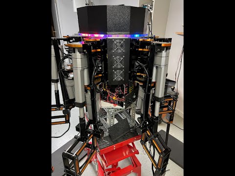
I didn’t show all the existing tests in the video, as I was filming you see that I found some math issues, some instances where a leg didn’t actually move to a position, and a handful of other errors that need to be tracked down. I troubleshoot and fix problems by creating a checklist of the problem, list any initial conditions (leg start/end position), and what test identified the issue. This way I can later re-run that test specifically to make sure the problem was corrected using the same conditions that created the problem.
Bob Sweeney
I’m in the unique position of troubleshooting my troubleshooting code….
As I try to narrow down and isolate issues to correct, I noticed something. I was getting a lot of error messages from the P1 controllers about, ‘Encoder not responding’. This particular error came about a while back when a leg would come up against an immovable object (another leg or the software position limits failed), so the motor is trying to move the leg but the leg physically can not move. That’s when motors fuses would blow or the motor overheats and damages the motor brushes. The answer to this condition is to compare the encoder reading to the previous 5 encoder readings as the motor is in its PID loop. 5 times around the PID loop without the encoder changing implies there is a problem so I shutdown the motor, exit the PID loop and export the error. During manual testing on the P1 controller I rarely get this error except when I purposefully block movement.
But now when testing using the P2 master, I’m getting this error often. Thinking it through, the biggest difference is that when manually testing, during each PID loop there are several troubleshooting print commands being sent to the PST that are not active when running via the P2. So I’m suspecting the printing code is introducing a delay that allows extra time for the affected motor to start up, take up any gear backlash, and start to physically move the axis which shows up on the encoder. If true, then when running from the P2, the motors are starting but there isn’t enough time for the physical aspect of the movement to get detected by the encoder before it throws an error.
So, how to fix it? I could measure the actual time the print statements take and use that value as a loop delay. Another option is to increase the number of PID loop cycles before evoking this error (instead of 5 loops, go for 10 non-moving encoder values).
Another related issue I noticed when I did the last video, 2 legs got the encoder error and did not move the femur while the other 4 legs did move the requested position. The right thing to do is to stop all leg movements if any leg is not moving as requested. But what about a situation where a move request happens and the move is just outside the motor’s PID deadband (dead band is set for 5 ticks of the encoder or about 0.44º movement). So if the error value is 6, then the move amount is 0.088º. The PID may not wind up enough to cause the motor to actually start moving (due to very low starting error value) before the encoder not moving error triggers. In this case the fact the one leg didn’t move a degree or two may not be an issue. Maybe I need to break the encoder error into 2 levels, small and large. Small errors could be tolerated but above a given value it requires all legs to stop.
IF PID_Output > Torque_Limit then PID_Output = Torque_LimitA stalled axis causes the PID_Ouput to increase rapidly (aka: Following Error)
Craig
Worth studying:
https://ruckig.com/#features
Craig
Interesting paper and video. I took a quick look at the C++ code, I’m not a C programmer so it will take some time to digest it all. I like it has a MIT license, could be fun to put together a demo and see what it can do.> @Mickster said:
I don’t have any means to measure torque output of the motors at this time. At one time I was looking at how to measure motor current but those sensors were out of my budget (since I would need 18 of them!) and I had run out of cogs to act on the data.
I do something along that line, by constraining the PID output (limit PID error based on experimental testing to limit output overshoot and still have fast initial response). There are also constraints on the servo output to the HB-25 motor controllers (1000-1500 msec for movement one direction and 1500-2000 msec for movement the other direction). The PID loop operates fairly quickly and the linear actuators have lots of internal gearing and then the output shaft is turning a captured nut that gives the linear output. I’m becoming more convinced the mechanical delay from the time the motor and gears start to move, which turns into linear movement of the output shaft and that process causes the affected axis to start to rotate, which is finally picked up by the magnetic encoder. I’d rather not put any ‘delays’ in the PID loop, so will be testing increasing the time frame the encoder not changing routine looks for non-changing values.
I am finding that I only get this encoder error on the femur and tibia, both use linear actuators. The coxa is a geared motor that drives a custom gear train and rarely gets an encoder error.
Hi @DiverBob
if you don't like the following, just forget it and sorry. But perhaps you can take something from it? Reasons to write this: I have seen your video now and the motions seem to be relatively slow, but on the other hand you seem to be struggling about control of movements for months now.
I have done some projects now with the propellers and some of them include motion control.
For me it seems, that your system with 6P1 + 1P2 brings very much to much complexity for this project. P2 should be capable of doing this task (control 18 slow axis) with only some primitive means to have more pins. How many FAST pins do you need for each axis? One counter input and one PWM output? At least I would degrade the P1s to very simple in/out chips and to concentrate all development work to the P2. I also think, it would be helpful to take out the P1s and if it is really necessary to have more controllers, use less P2s instead. The reason is, that there are so many differences between P1 and P2.
My experience is, that it is only of benefit, to split tasks, if they are really rather independent. If they are not, it is better to keep them closely together. I have had a setup, where I had a raspi connected to a P1 to control my little lathe. I last year did throw out this P1 and got a very much simpler system which is even faster through some other optimisations.
(I don't know, if it is feasible with this actor mechanics, but it would be very much less complicated to use stepper motors, because in this speed range you won't need a feedback loop. At least not permanently. The only downside here is less efficiency for the battery operated robot.)
For such type of project, where there is no series production but a lot of experimenting and tweaking an interactive language can be very helpful! With the interactive console you can look at variables, change parameters, even change parts of code without the need to recompile everything. While Micropython would be convenient, it is too slow and much too big for P2. Tachyon / Taqoz Forth will give you about the same speed as Parallax SPIN but it has the huge advantage of being interactive. In some papers of the 80ies about Forth there is the statement, that software development with Forth would be 4 times faster than otherwise. For this type of project, I think that can be true. Well, Forth is a bit weird, but you would get used to that. I would be rather astonished, if P2 with Taqoz Forth would be too slow for these 18 axis in a single cog.
As far as I understand, your goal ist to climb stairs. For this, I think it is mandatory to have the possibility to "feel" the stair. Very many stepper controllers have current feedback. This is indeed rather simple. It is just a shunt resistor in the connection to ground, a rail-to-rail opamp and an analog input. https://st.com/resource/en/application_note/an240-applications-of-monolithic-bridge-drivers-stmicroelectronics.pdf (Also you could measure emf voltage to have speed feedback.)
So, while Mickster comes from a background of very fast movements, my direction of view is here, how can you simplify things to go forward more easy. One question would be, if you really need PID at all in this case. Perhaps it is good enough to simply switch off the motor, when the position is in a window of counts around the theory?
Some years back I learned about human movements, that for fast movements there is no feedback loop at all! Instead the human has to learn beforehand, what command to the muscle is needed in that situation. So if you pick up something that has very much less weight, than you thought, your movement will overshoot. Movements with feedback loop by the eye or other sense are VERY much slower.
So perhaps there can be a small number of situations (=load) which define the width of the window to switch off the motor.
Just some thoughts, cheers Christof
Thanks for the input!
1 - When I started this project only the P1 was available. I quickly determined a single P1 didn’t have enough horsepower to do the math and handle all the inputs and outputs I needed at that time. I was running each motor in its own cog to run DC motors like a servo. It may be possible with smart pins to run everything on a single P2 but I’m not quite ready to abandon all the work I’ve done so far. Besides, the comms between the P2 and P1’s has been worked out pretty well and I don’t believe they are really a factor at this point. At this point the P2 handles all the mathematics and just hands off actual movement to the P1 controllers.
2 - I went with DC motors using linear drives is to reduce power draw. When the motors are powered off, the legs are mechanically locked in place so power is only needed during actual movement. Direct connected steppers would require power all the time otherwise the weight of the robot would cause the steppers to rotate once power is removed. Steppers of a size that could handle this weight are very expensive and use a lot of power. I could potentially replace the DC drive motors with steppers and retain the linear actuator mechanical portion as an option. Or am I misinterpreting how you mean to use steppers?
I’ve actually been looking for brushless motors that might replace the DC motors but haven’t been successful in my search (there is also a budget constraint involved there too!). I would love to experiment with the type of motors that Boston Dynamics uses for their robots, but I imagine they are way out of my price range!
3 - I’m not sure what you mean by interactive console? Between Chip’s new debugger and the logic analyzer, it has become much simpler to figure out what is going on and narrow down errors. I primarily use Spin with some in-line assembly in time critical parts. I have also used FlexSpin but like the Parallax Propellor Tool the best. The Propellor IDE is also very nice but for some reason it doesn’t want to work properly on my setup, haven’t wanted to devote the time to figure out why…
4 - I will look at your link for current feedback. I had looked at some current sensing several years back but the need to have 18 of them coupled with the P1 limitations had me looking for other solutions instead.
5 - I have tried a variety of motor control schemes over the years and the PID loop with the magnetic encoder feedback has given the most precise control of all. Simply turning the motor on and off was one of the first setups, followed by a S-curve algorithm for motor starts and stops. There may have been a few other tests in there too. I’m pretty happy with the results the PID loop as compared with the other options I’ve tried, I’m sure my version of implementing a PID loop could be simplified or coded more efficiently.
I really appreciate your feedback and don’t think I’m discounting what you pointed out. I wanted to let you know the reasoning behind why I am doing things the way I am and how I got to this point. This has been a long project that I have really enjoyed playing with and since no one is paying me to do this, there is no set schedule for completion. I’ve learned a whole lot of new things (CAD/CAM, anodizing, battery tech, software techniques, P2 assembly language, just for starters) along the way. Half the fun of this project is having a problem and figuring out a solution! Once I actually complete this robot and get it walking and eventually able to climb stairs, then I’m not sure what I will do with it at that point! More than likely I‘ll look into more automatous operation but mostly this is a platform that gives me a good excuse to keep on learning new things. I post my progress on this thread just to encourage other robot enthusiasts and get suggestions when I do have an issue.
The technology has advanced over the time I have worked on this project and in some cases I am keeping with the older solutions (P1’s, HB-25) just because everything has already been designed around them. Another consideration is cost, there is some great improvements in motor technology that I would love to incorporate but the cost is way out of my hobbyist budget, especially when I need at least 6 of each thing. The hardware was also designed around using specific form factors and larger motors, steppers, brushless motors, gearing systems, etc in most cases would require extensive modifications to the hardware. So that also limits my ability to make hardware changes. Lastly, there is only one programmer/worker on the production team, me! So that is a limitation as everything is based on my abilities to perform what ever task that needs to be done. Luckily there are a lot of on-line robot and Parallax enthusiasts that have helped with ideas and coding over the years. I wouldn’t be as far along as I am without their help.
Bob Sweeney
Hi Bob, glad to see, that you appreciate my comment. I had thought about something like this: https://amazon.de/Iverntech-Schrittmotor-integrierter-Bleischraube-CNC-Maschine/dp/B0776F4BKH/ref=sr_1_1_sspa?__mk_de_DE=%C3%85M%C3%85%C5%BD%C3%95%C3%91&crid=2HAJBPLFGNL7J&keywords=gewindespindel%2BSchrittmotor&qid=1681658843&sprefix=gewindespindel%2Bschrittmotor%2Caps%2C83&sr=8-1-spons&sp_csd=d2lkZ2V0TmFtZT1zcF9hdGY&th=1
You can buy the spindles separately too to combine them with stronger steppers. These spindles will hold the position without power.
But if you are happy with your actuators, there is no need to change anything. - I also do not see any advantage for brushless motors for such project. Advantage would be lifetime of the brushes, but this is not relevant here. To drive the brushless motors is more complicated.
Interactive console means, that you have a serial connection from a terminal window on your PC to P2 and can give commands to the system, like in the shell of linux or MS-Dos. You can start programs, compile them, You can display variables or set them. You don't need to plan simpler things, just type your command. Want to know the position of axis7. Just type "axPos7 " (or whatever the variable name is) "@ . " . If you want to correct the position to 100 units, just type "100 axPos7 ! " Forth was first used to control experiments, it is an experimenters language. Taqoz Forth comes very complete with lots of features. If one motivation for your project is learning new things, you could have a look at murphywong.net/hello/simple.htm .
I would not recommend to use Forth on a PC, where you can use other systems, which have so very mighty libraries. I would also not recommend to use Forth on a project in a big firm for a system for mass production. But for such project like yours here and most of mine, where so much time is experiment, this language is just right. Forth had it's high time, when personal computers had 16k...256k RAM and just some floppy disk as mass storage. Too low memory to run a conventional multitasking system. P2 has got just the right power and amount of RAM now for it. Well, sorry, if the fascination has caught you, it is sometimes hard to understand, why Forth is not used more in such cases.
Good luck with your project!
Christof
Personally, I believe that the motion aspect is going off on crazy tangents and that we need to start over. But I can't seem to structure a post that doesn't come across like I'm some arrogant a$$
Craig
Well, Mickster and Christof, you got me thinking about my issues over night (I can’t go to sleep due to all these thoughts running around my head!).
So I spent a few hours coming up with a much simpler motor control solution that I coded and tested. Initial results show it works pretty well, not as accurate as the PID but there are lots fewer things that can go wrong in the code. The PID code has grown over the years as issues were solved or new features were added so there are just too things that can go wrong. I finished coding the Femur and Tibia motor control loops, in many ways they resemble the PID loop in that I still have all the error checking that the P2 side is expecting. I still have to do the coxa and then manually check each axis movement to make sure I didn’t forget anything or find any hidden problems. It has been pretty easy to troubleshoot so far as code size has been reduced by 2/3rds.
Sounds good! Congratulations!
When I have a look at your mechanics, I ask myself, where there is elasticity in your setup? I think, that in the human body or body of animals, there is plenty of deflection which prevents from being hurt and reduces the need for precision of position very much. It seems to be a mixture of controlled position and controlled force. On rough terrain or on grassland, you can't know at what depth the solid ground is.
Just a few thoughts,
Christof
The leg mechanics were built to 0.001 tolerances with bushing and bearings at 0.0005 tolerance. This makes the leg fairly rigid. However, then I added in the Linear Actuators whose connection points have a fair amount of slop (tip of leg can move about 1/4” up and down). The coxa gear train is fairly rigid, that induces less than 0.1” movement side to side measured 6” from the body. So there is some elasticity in each leg measured at the leg tip. Knowing the amount of ‘flex’ at the leg tip allows me to play with the accuracy of leg movements when figuring out straight line paths for the leg tip while moving. I have the leg down sensors for determining where the ground actually is when moving in uneven environments, but for now I’m assuming level ground.
Today I tried to implement the same motor control coding in the coxa as I did for the femur and tibia. Although I got it working, the accuracy was extremely poor as compared to the other 2 axis. I think that’s because linear actuators have a lot of ‘slop’ in the mechanism where the coxa gear train was built to higher tolerances so there is a faster motor response but slow stopping after it gets going. So even short moves resulted in anywhere from 1º to 3º movement after the motor power was removed. After a couple of hours trying to improve its accuracy, I rolled back to the PID control for just the coxa. This gives about 0.4º accuracy very reliably.
More testing tomorrow, update my notes, and then power everything down while we take off for a much needed trip!
Bob,
Have you thought about just redoing the entire thing in cast iron, you know, just to dampen the harmonics?
I hope you are joking!
We are back from a very long trip and finally caught up on all house and yard work so getting back into the robot again.
The first thing was updating SpinIDE, I can now run Debug on it so I’ve started using it instead of the Prop Tool. I especially like the right side list of all functions, makes it real easy to quickly jump around a large program!
After getting the battery recharged, I utilized the test routine I programmed in right before I left on our last trip. I started with running the first test which just displays the current status and position of each leg without moving the leg. I got communications errors from each leg except leg #1 (Leg 1 is typically the leg used for program testing before updating all other legs, plus its happens to be the leg facing me on the test stand). It took a while but I narrowed down the problem and got a fix.
Next step is one of several leg movement routines that ensure all leg software limits and sensors are working correctly. Should run that today.
Don't forget battery weight! Easy to overlook.
Always fun to be troubleshooting code, especially code that was working earlier.
I was getting errors during the startup where all legs were pre-positioned to a specific location. However several of the legs did not even attempt to move and there were several unexpected errors indicated by the debug texts. One error was the leg down sensor was activated even when the leg was several inches off the floor. That was a tough one to figure out but it got resolved. I made a mistake in the code by treating this sensor as an error condition when it is actually a notification of a condition. Errors are handled by stopping movement to prevent damage, sensor notifications are only acted upon based on the current conditions. Once I got the sensor in the right category, everything started working better.
Working my way through the remaining issues, the RGB display lights and all 8 channels of the Salae logic analyzer are being used to track down problems along with the Debug commands.
All legs are moving correctly when individually sent movement commands, some problems appear when several legs are supposed to move and don’t, even when the correct command string is transmitted. This might be a timing issue where the P1’s can’t keep up with the P2 output commands. I’ll be testing this next.
After simplifying the PID code for Femur and Tibia motors, the leg down sensors stopped working. Indications seemed to say the library object was at fault but when I run an earlier version of the code before the PID changes, the leg sensor works perfectly. I finally found a copy/paste error where the ADC object was being started in both the Femur and Tibia cogs. Funny how one line of code can really mess your day up! Now it is working correctly.
This fix also corrected some strange P1 to P2 feedback data that wasn't frequent enough to pinpoint but was causing the P2 to react and then legs were moving to strange positions. The fact that the legs were moving inadvertently (mainly during startup of the P2 and P1 processors) so I need to come up with a way to ensure the motors aren't enabled until the computers are up and stable.
At this time I am still checking out the new PID routines on the Femur and Tibia. Still working on the motor movement issue described in the previous posting. I have some new testing code in the P2 that is allowing me to be more consistent in testing and not get distracted when something new pops up.
Continuing work on finding and correcting strange code issues that arise.
Fixed issue where after power was applied to the robot or when uploading P2 code changes, the P1 controllers would occasionally move on their own. Tracked it down to incomplete movement commands were received by P1 controller so added check to verify a complete movement command was received prior to moving leg
Kept getting situation when moving all legs that not all Tibia motors were responding. Verified good movement commands being sent. Problem in the way tibia code sometimes thought the movement was less than the deadband. This seems to be fixed but more testing needed
I've started working earlier than expected on the robot as normally my wife and I are traveling through the spring and fall (summer is outside and house projects). Winter is my robot project time but this year when we got on the road for the fall trip, the motor home caught fire. Luckily no one got hurt and I got the fire out before the motor home burned up, however the damage is extensive. So no long trips for a while until insurance works everything out.
Yikes! Hope you get it all sorted out. Fire no fun ..
Lots of coding and testing has been going on in between all the other stuff life throws at us all the time!
I’ve been reading and researching on how to make a leg move in a straight line. There a few examples out there, some even have some code attached for study. I’m working out my own ideas, mostly on paper so far with a little bit of coding to see how it translates in Spin.
I had an ‘ah Ha’ moment when I realized I could use the center of the robot body to help figure out movement. If I overlay a XY graph over the body with point x=0, y=0 centered on the dead center of the robot body, this actually simplified a few items. So if I assume leg1 is located along the Y axis, then leg2 is 60º clockwise from that and each leg is another 60º apart. Since the planned user input device for movement will be a joystick and we assume straight up on the joystick represents y= some value and x=0. The joystick position determines the direction the center of the body will travel and how far over the joystick is moved will be the amount of distance a leg will move in that direction for each step.
The joystick output is then used to compute an X and Y value along with an angle. This becomes the basis for movement.
Since each leg is offset by 60º, the angle the body is moving can be converted into an angle for each leg based on the leg’s position around the body. The spot where the leg tip is located at is used as the starting point, so with the desired angle known and the length of the body movement known, the XYZ coordinates for the desired endpoint of the leg can be calculated.
Since we don’t want the leg to move directly between the starting and end positions (each motor moves the leg tip at different speeds), the move between the 2 points has to be broken up into smaller segments. Each movement segment has to have the XY and Z values calculated by the P2 Master computer and sent to the leg controllers. These segments have to be small enough that the leg tip moves will approximate a straight line, too large of a distance between intervals could damage the leg. Too small an interval can result in the P2 not being able to keep up with all the calculations during leg movement time which would result in the leg jerking. So there will have to be a compromise to figure out the best movement interval.
That’s where I am now, coding the movements to allow at least one leg to move in a straight line. I’ve started with a long distance between 2 points and increasing the number of waypoints between the start and end positions. I’m looking for how small a waypoint can be and how smoothly a leg transitions between each point. Then I add additional legs to do the same thing.
I suspect this will keep me busy for a while.
@DiverBob
"Too small an interval can result in the P2 not being able to keep up with all the calculations during leg movement time which would result in the leg jerking. So there will have to be a compromise to figure out the best movement interval."
Are you aware, that it is one of the unique features of P2 to have a "Cordic Solver" that can do polar to xy and xy to polar coordinates conversion in hardware? It can do such conversion in 54 cycles, so 3 millions of these per second! (If you overlap these somehow, even more.)
From the spin2 manual:
ROTXY(x, y, angle32bit) : rotx, roty
Rotate (x,y) by angle32bit and return rotated (x,y).
POLXY(length, angle32bit) : x, y
Convert (length,angle32bit) to (x,y).
XYPOL(x, y) : length, angle32bit
Convert (x,y) to (length,angle32bit).
Even if the SPIN2 interpreter will be much slower than the Cordic Solver, there should be not much of a bottleneck, if you use these functions.
Good Luck, Christof
Yes, the routines are using the Cordic engine in the P2 and all the math is being done as integer math vs floating point. I fully expect the P2 to be able to handle the load. For time critical routines, I have been using the in-line PASM to improve the speed.
This might be similar to the inverse kinematics math done for the dog bot
First movements using Inverse Kinematics (IK) have been accomplished! The movements are on a single leg and are very jerky (expected). This is due to all the debug statements as I want to see each incremental step and make sure the movements are being calculated correctly. Lots of debugging going on, for instance the first movement was to be over a span of 300mm and each increment was 5mm. This came out to 60 individual movements. The leg ended up in an unexpected position but the debug helped pin point that on the 13th movement, the tibia reached its limit of travel which caused a cascade of other issues. Coded in an abort if any leg limits are reached which solved that issue. Next run of the same parameters showed the Femur suddenly moving to an unexpected position at the end of the movement. This appears to be an issue with the IK math, I believe the math is calculating an ‘impossible triangle configuration’ and invalid results are coming out. I have to manually enter the values into a calculator and verify if this is the issue. If this is the problem, I need to come up with some way of recognizing when this happens. I always knew this was a possibility but this is potentially the first time I’ve actually run across it.
I’m also tweaking the code to allow the leg to move smoother between calculated stops. Right now all 3 motors start to move and feedback to the P2 when they have finished the move. All 3 motors have to finish moving before the next command is issued. Ideally there would be a way to anticipate when each motor is almost at its stop point and then send the next command so the motor doesn’t actually come to full stop.
The document attached to post #1002 explains how this works.
Under "path mode"
This is all standard stuff.
Craig.
I remember when you posted this earlier and I appreciate the PDF link. I looked into it earlier and as a pre-programmed PIC, it has some great features. My setup would require quite a few hardware changes to implement that PIC that I’m not ready to take on at this point. I want to see if I can implement the same kind of capabilities just using P2 coding. If it eventually turns out that I’m not getting the results I want from that approach, then I’ll start looking at hardware changes.
There is also a cost consideration, individually the chips are $30 each, a pre-made control board with the chip is $154. That adds up quickly when I have 18 brushed motors to control!
The jerky movements I’m getting now are fine and expected as I’m just making sure the basic code and math routines are correct so there is a lot of debugging code in there to verify variables are changing as expected. This approach has helped me identify a few problems I hadn’t thought of before. Once the math is right (mainly finding math errors or invalid trigonometry situations now) then the debugging can be removed and I’ll figure out how to sequence the movements to get smooth movement. There are some good ideas in the PIC-SERVO SC documents that I can use to get smoother movements
You have a coordinator...the P2 and you have P1s handling the motion(?)
Whatever sample-rate you are running the PID on each P1(1KHz is typical), needs to be the incremental update of the motor position command.
For example; you need the motor to move 1000 cts @ the rate of 1000 cts/sec. Each iteration of the PID loop, increments its position command by one count. Assuming the PID loop is running @ 1KHz.
You need to arrive at the position in 0.5 sec? Each iteration increments the command by two counts.
You don't need/want to be bombarding all P1s from the P2. Have the P2 update the P1s at say 33Hz and let the P1s take responsibility for scaling the position commands to the PID sample rate.
Meanwhile the P2 is doing the number crunching and dishing-out updates to the P1 buffers. As each P1 completes its command, it grabs the next one from its buffer and motion becomes smooth and continuous.
Each P1 maintains a status byte which informs the P2 of:
Motion complete
Excess error
Buffer full
Checksum error
Etc
Etc
Craig
Thanks for the input Craig. I’ve been mulling over what you said and have re-read the PIC Servo document several times to understand the principles behind the way they handle motor movement.
The way my code is set up, each motor PID is running on its own cog, the cogs PIDs are not synchronized with each other and run independently. The code for each cog runs at the full speed of the cog at all times. There is a flag that indicates when the motor is at the requested position and an output that shows the current linkage angle as the motor is moving. Motor position is not measured directly at the motor but uses magnetic angle encoders that measure the angle of the linkages connected to the motor.
The P2 movement request specifies an angle for the motor to move it linkages to and that’s what gets measured. So I’m trying to think of how to coordinate the motors so each arrives at the specified location at the same time.
To sum it up, initially I need to know how much each motor has to move to get to a requested position, however the amount of actual movement needed to move a specific number of degrees is different for each motor due to the mechanical linkages. There is probably some fixed ratio of movement to degrees between each motor. That could be useful but I’m not sure how to figure that out. Eventually it comes down to being able to adjust each motor’s movement so they all arrive at the requested point at the same time. I’m trying to think of ways to accomplish that. This probably the key item needed to accomplish the next part of the puzzle.
The other part of the puzzle once figuring out how to get each motor to more or less stop at the same time, is to set up the P2 to push several movement commands into a buffer on each leg. Currently the P2 waits for each leg motor to report that it is in position before sending the next movement command. Since each motor has stopped at this point, power has to be reapplied to the motor to get to the next location, resulting in the leg jerking around. The plan is to get the motors moving to the next position once they are almost at the current position and haven’t actually stopped yet.
There are several variables used in each PID loop but I’m thinking using motor speed might be a way to control this. Motor speed could be used as an indicator since after a position command is received, the motor speed ramps up quickly to some value and starts to come down once it gets close to the target. Identifying the maximum speed and signaling when the ramp down process starts could trigger grabbing the next position request if it gets stored in a buffer. Then the motors don’t actually stop but start processing the next location. If the inputs buffer is empty, the motors stop at the final position.
Hopefully this explanation isn’t too confusing…. So if anyone has any ideas, I’d love to hear them!
Bob