@Mickster said:
I usually get my wrist slapped for critiquing, so I'll drop it.
Craig
I don’t mind getting comments and ideas, it makes me think outside of my own little box! I’ve used a lot of input from others over the years in the design. I have an engineering background so when I started this project I developed a ‘test’ leg to find out the weak points around the design and put in compensations to reduce or eliminate potential issues. At this point the legs have been tested mechanically quite a bit and have proven to be fairly robust so I’m not too worried about that part. Now I have to get the programming down right so it can start walking.
Finished 5 of the 6 leg mods, last leg is off the body and disassembled so I can hopefully finish it up tomorrow. Then I can get back to calibrating the coxa mechanism again.
It took longer than expected to complete leg coxa calibrations. I was calibrating the first leg when I found the motor could only rotate the coxa about 120º and not the expected 180º. That’s when I realized that the moving part of the leg was getting caught by the top part of the new cutout in the side supports. This didn’t cause any motor damage as the program stops the motor if the encoder output value doesn’t change when it should be changing. Turns out that with any weight on the legs the movable section could move up about 0.05” and get caught on the metal edge. Most of the legs were susceptible to this problem so that required removing the side supports again, widening the gap by 0.125” and then reinstall.
Once that problem was solved the actual calibration went fairly smoothly. I was able to test each leg individually and made sure the leg moved freely from 0º to 180º on each coxa. In some cases various motor or sensor wires got pinched which stopped the leg from moving but that was fixed using zip ties to keep the wires in the proper locations.
Today I hooked up the logic analyzer again and started controlling the legs via the P2 master computer. So I’m finally back to where I was at a couple of months ago! Anyway, I am coding to move a single leg tip in a straight line based on input from the direction the hexapod body is moving. This involves a bit of math again as the 6 legs are arranged every 60º around the body and if using the body as the primary coordinate (x,y,z) system, body movement has to be then converted into coordinates that each of the individual legs can understand.
Another part of the programming is getting the leg tip to move smoothly as each motor has a different runtime as it gets the leg tip into position. Right now the leg tip is moving 10mm in the X and Y axis before stopping and getting the next position so it isn’t moving as smoothly as I would like. I will be experimenting with different movement increments, checking when each motor has stopped running, and using timers to find the best movement algorithm. The logic analyzer is great for this work as it can pinpoint when specific processes start and end. Still working with a single leg right now, will add a second leg into the mix once some of these questions have been answered.
Not a good day! Started up the computer and installed the latest version of PropTools. Ran the spin2 code and got an error that debug communications was lost. Tried again, same result, uninstall and try again, same thing. Uninstall and then re-install the version I had installed earlier, now it says the same thing. To top it off, the Logitech mouse stopped working, had to find a wired mouse to get going again. Come to find out the computer bluetooth is OFF and according to all the troubleshooting measures I have run, it isn’t even installed. Located a Logitech bluetooth adapter that plugged into a USB port, got the mouse running again.
Tried PropTool again, same problem. So I decided to run the latest version of FlexProp (I’m a Patreon so have access to the newest version) and it isn’t running a debug terminal at all, although the previous leg program did run and the leg was moving. Just no debugging data to analyze.
Next stop was SimpleIDE, it had issues too. So after a few hours of beating my head against the wall it was time to take a break and shut everything down for a while, get back tomorrow with a fresh start.
Grrrrrrr!
Back to the computer today, now the built-in bluetooth is working again so I was able to remove the logitech dongle and get my mouse working right!
I installed the newest version of the Prop Tool (2.9.3) but I get a Debug Communications Lost error so nothing shows up on the debug window but the program is running as the robot is moving a leg according to my last test. I found this error is occurring on all the 2.9.x versions of the program so I had to revert back to 2.6.3 to get the debug working correctly. Unfortunately this means I can't use the new single stepping ability but right now I don't really need it for the tests I am running.
So right now I am testing using leg1 and having the leg tip move in a straight line. The code works but the movement is not as smooth as I would like. I think I need to go with a smaller step value (set at 5mm now) to get it right. The code looks at the X,Y, Z leg coordinates and divides each axis up by the step value, then it advances each axis in discrete steps to the end point. A better way may be to break up the hypotenuse (the distance the body is attempting to traverse) into steps, calculate the the X, Y step values from that instead. Have to think about that some more and figure out how to code it (this may actually be a simpler way of doing this).
I plan on doing some more videos once I get some more progress. I'll also go into more detail on the math involved with moving a leg in a straight line and then moving all the legs together.
If I understand what you mean, those way-points need to be discreetized, based on time (trajectory generator).
I recently learned that Kuka Robotics have an update rate of 14ms (don't know where that particular number comes from). I typically run at half the rate of the PID loop. So, if my PID runs @1KHz, the trajectory generator runs @500Hz.
With some great insight from Jeff Martin, the debugging error has been solved. Turns out that the Rev A & B versions of the P2 Edge board TX pin is not pulled high and ends up throwing the debug communications error. I swapped the Rev B board for a Rev D version and it started working! Jeff said addition of a resistor to the TX line can fix the problem, I a waiting for a response on recommended resistor size and installation location so I can fix the 2 earlier edge boards.
So now that I can run version 2.9.3 of the Prop Tool, I was able to start using the polxy() method instead of my workaround.
So running a simple test where I tell a leg to lift up 100mm and measure the actual distance moved. The actual distance moved was 108mm so there is a 8 mm discrepancy to look into. With different lift distances I get smaller errors: 10mm -> 2mm overshoot, 50mm -> 4mm overshot. The error progression is linear so it is either a calibration issue, the PID overshooting the target value, or additional mechanical movement after the target is reached.
I noticed when I went with a 150mm lift, I got strange results, the tibia moved to 8.9 degrees with no upward movement of the femur. The command sent was for the femur to move to 20.5 degrees which is outside the allowable range. The P1 controllers picked up the bad command, sent an error message to the P2 but the P2 error debug didn't pick it up other than to light up a red error light. So something else to track down!
@Mickster said:
If I understand what you mean, those way-points need to be discreetized, based on time (trajectory generator).
I recently learned that Kuka Robotics have an update rate of 14ms (don't know where that particular number comes from). I typically run at half the rate of the PID loop. So, if my PID runs @1KHz, the trajectory generator runs @500Hz.
Craig
Thanks for the information, I'll use this info once I track down these other errors!
Another good day (mostly) on the robot. Today I worked on a couple of simple routines that allowed me to raise and lower the robot body by sending the same command to all 6 legs at the same time. It mostly worked but I had a few minor glitches that need to be sorted out. I also need to re-attach my safety rope to the body for those situations which don’t go quite right! I put together a short video showing the robot movements, the way the RGB lights are using for troubleshooting and the debug window which is where most of the troubleshooting is coming from. As you can see in the video, I extensively use the debug window to capture starting positions and the end positions of each leg and the input coming back to the P2 from the individual P1 controllers. https://youtu.be/EMEnAwUO_Ls
I’ve been adding more code to catch errors but you can see in the video there are still some bad commands coming through that I have to find the source and make corrections.
I’m not sure you could see it in the previous video but the code was basically telling each leg to move the same amount in the downward direction. To do this the P2 takes the current X, Y and Z position for the leg, uses IK math to convert that to motor angles. The resulting angles are checked to validate they are in the proper range. If no errors, then the resulting movement command is transmitted to the corresponding leg. Then it repeats this process for the next leg. What I noticed is the the very slight delay in the start times for each leg’s movement. The logic analyzer shows about a 57ms delay between P2 transmit cycles, so around 300ms for all 6 legs.
I think delay is also the cause for the problem I found on leg 4 after the program ran, leg 4 leg sensor was no longer touching down. That’s because after leg 4 actually ‘touched’ the ground, leg 5 and then leg 6 drove their legs down until their sensors sensed the ground. This most likely resulting in lifting the robot body just enough where leg 4 sensor wasn’t firmly on the ground.
Thinking it over, the goal would be to minimize the delay between leg motor starts. The one way I can think of is to get all 6 leg movement commands figured out and then transmit them without the delay while the P2 figures out the next leg’s position. This way all the calculations are made up front for a leg move and then the P2 is just transmitting movement commands until told to stop or new parameters are entered.
For raising and lowering a leg that is pretty simple, I just need a buffer for each leg that holds the up or down movement command. But it gets more complicated if the leg is to make a step, there are potentially quite a few interim movements between the start and end positions. The array size could get large and unwieldy. I’ll try a simple test just like the current code where I just raise and lower the legs, see how much faster the P2 can transmit that way. I can also increase the P2->P1 transmit speed (set at 57600baud) and see how that goes. I picked this baud rate back when I was using a P1 as the master and it was about as fast as I could get reliable data between the units at that time.
FWIW: I went with this arrangement but using a 3K3 pullup. P2 talking to four RPi-Picos. Pico Baud limit is 921.6 K. I don't need this speed but used it to test for reliability
First I changed the transmit and receive speed on the P1 controllers, increased the baud rate to 115200, no errors identified either receiving or transmitting at this speed. Haven't tried going higher, not sure that would improve anything anything although the interval between output P1 feedback went from every 6.68msec to 8.7msec just because the data transmits faster.
When manually testing this speed change out on leg 1 (I have the computer physically linked to leg 1 and running it in manual mode, all other legs are still in automatic mode which is waiting for a command string from the P2 module - no program is running on the P2 at this point), leg 6 suddenly moved to the 0 degree position on the coxa, causing some interference with the leg 1 movement tests I was performing. As I wasn't sending any commands to leg 6, nor was the P2 master running any program, this indicated some type of problem. I set up some movement scenarios and discovered that now that the movement range for the coxa goes from 0 degrees to 180 degrees, it was possible to 'accidentally' have a 0 sent as a valid movement command for the coxa. The P1 code brings in the movement data, extracts femur data, sends that to the femur PID, next it extracts tibia, then coxa. If the coxa value is missing (such as an incomplete command string goes to the leg), then a 0 can be sent to the coxa PID, this wasn't a problem when the minimum coxa value was 32 degrees.... Changed the P1 code to extract all the data from the P2 input string up front, if any data is missing that sends a -1 value which prevents any of the motors from being activated and sends an error code back to the P2.
I also re-introduced transmitting a leg number in the movement string to help prevent spurious input commands. This was part of the original communications design when all P1 receivers were tied together. When I rewired the system so each P1 was wired directly from a P2 output, I removed the leg number data as it appeared to no longer be needed.
Of course any changes like this introduces other issues that have to be tested, errors found, code fixed, repeat! I think I may have broke the HB-25 motor controller startup code somewhere, it's requiring the motor controller to be cycled off and back on again for them to actually work. Had to search on-line for the manual since I couldn't find it on their website anymore. So going over the manual to see what I might have accidentally deleted or changed in the P1 startup code.
Mickster - Thank you for the information, I'm still processing that in my mind and trying to figure out how that could be used in my situation. I read the PIC-SERVO manual, have to see how that information can be used.
Mickster - I've read the PIC SERVO document a few times now and got some ideas try out.
I did a couple of mods to the Femur PID code and discovered a coding error that's been there since I first typed it in. The results of the error were hidden but caused the PID loop to overshoot in some circumstances. I corrected that and went into a in-depth review of that code to see if there were other hidden problems or things that got added to the code but were no longer needed. I did try removing the integral portion of the PID controller but got much worse response so put it back in again. I did change the Pi value to divide it by 8 to reduce its overall effect. That resulted in a faster response without an endpoint overshoot. The derivative (Pd) value I'm still fooling around with. One of the ideas from the PIC SERVO document was an option they have where the you look further back in time at earlier error values which can inflate the derivative which would have the effect of toning down the Kp value. I have to figure out a way to retain those earlier error values, right now I only save the immediately previous error for use in the derivative.
Next I will finish testing the code modifications and then dump it to each leg controller. Then I can get back to working on the P2 again (assuming the P1 code changes work the way they are supposed to once the leg controllers aren't in manual mode!)
Anyway, its more fun playing on the computer in the basement than the cold wet day that Michigan has for me outside!
Derivative for me is typically 5 to 10 times the proportional. In 40 years, I have never had success with integral, during motion. It resulted in huge machinery dancing across the floor
I played with the SRD (I just used a 4-element array, shoved the latest D into the first element, shuffled the others down and discarded the oldest value). Didn't need it though because my encoder line-count is either 2048 or 4096 (8192 or 16384 quad counts/rev).
I had no idea that you are in MI
This was my CNC Tube-Bender factory in Wixom 48393:
I’m on the other side of the state from you, in Saint Joseph, MI. I live about 6 miles from Lake Michigan and all its fun weather it throws our way!
I used to have to adjust PID controllers in my Navy days and taught PID controller theory at power plants (among other things!). However this is the first time I’ve written software to do what I did with analog in the past. It’s been a learning experience but I’ve had fun even when it didn’t work the way I envisioned it.
The resulting PID code has been tweaked quite a bit over time and some older ‘fixes’ have become un-needed at best and potentially harmful at worst. I’ve cleaned up the code by going line by line, commenting out portions of code that don’t make sense anymore and then running some quick tests to ensure there wasn’t a hidden reason for it. My program notes have become better over time so that helps a lot in determining the code usefulness.
Today was just too nice to be inside so planning on some evening programming/testing later.
Oh I am still a fan of the analog stuff. I frequently come across one of my late 1980s machines. Brush-type motors, tach feedback, potentiometers on the drives....Just like new, never been tampered with and they've been ridden hard.
Today, a technician can't do a darned thing without a laptop and the setup software usually sucks.
My aim is to make everything simple and fixable again....it's a conspiracy I tell ya
The traditional suppliers are really screwing over the industry with the BS.
I have dubbed my P2 controller "MTTR ZERO-H" (mean time to repair, zero hours).
Update time!
The last week has been spent testing the PID and communications mods and fixing any new problems they introduced. I found I needed to re-calibrate the 3 axis encoders again so after a couple of days doing it manually and then getting inconsistent outputs, I decided to write code to assist in the calibration. Once I got that entered and fixed, calibration is going a bit smoother. Basically I have to drive a motor to its extreme limits and get the encoder value at that point. The tibia motor was proving to be a bit troublesome, at the extreme minimum angle, the tibia was at a negative angle. However the tibia linear actuators can be manually adjusted by disconnecting them and the output shaft can be screwed in and out to lengthen. It takes some trial and error to get the shaft to the right length so that the tibia angle is = 0 degrees.
Finished up leg #1, pushed the program updates to EEPROM on the P1, got about halfway through leg #2.
Successfully calibrated and updated all 6 legs. Back to testing the legs using the P2 Edge module again. Starting with checking each individual leg (ensures commands are being transmitted by the P2 and the P2 gets the appropriate feedback from the P1 controllers). Then its back to where I was before I was before I diverted back to coding the P1 controllers.
As i was planning out my next steps, one thing I realized is it would be possible that over several steps the legs on one side of the hexapod could gradually become higher or lower due to the rounding in the math routines. I think it would still be able to move but would grow increasingly lopsided until a leg reaches a hardware movement limit. To counteract this, I need the P2 to monitor the inclination of the axis so corrections can be made to the gait. Parallax has several tilt sensors, I have several of them in my parts drawer! The best one for me looks to be the LIS3DH 3-Axis Accelerometer with ADC module. It has some P2 code I can try out and see what kind of output it creates so I can figure out how to incorporate it into the robots code. Could be a fun little diversion when I get tired of testing…..
Thats inclinometer idea is interesting. I assume there would be one in the body to serve as a master reference to compare the legs to if the whole beast was on a slope? And if this was true, is there a reason you couldnt use each legs incline sensor for absolute position on-the-fly?
@JRoark said:
Thats inclinometer idea is interesting. I assume there would be one in the body to serve as a master reference to compare the legs to if the whole beast was on a slope? And if this was true, is there a reason you couldnt use each legs incline sensor for absolute position on-the-fly?
Totally crushing on your mischief here!
You are right, the idea would be to install the inclinometer to the main robot body. The legs don’t have any tilt sensor on them, just magnetic encoders and the leg down sensor. This will also be useful whenever I get to the point where it’s time to teach it to walk up stairs.
Had an interruption in testing the P2 side of the robot, I found that errors generated by the leg controller were not clearing so the P2 isn’t sending the next set of instructions. Since I’m checking for quite a few error conditions, the P2 side to acknowledges the error and either ignore it if it isn’t important in the current condition or acts upon the error. But I didn’t build in a way to reset an error from the P1 leg controllers. So I came up with an error reset mechanism that allows the P2 to selectively reset individual errors or all errors coming from a leg controller.
So after that delay, I’m back doing the testing of the leg controllers. This testing is basically manually running a series of code routines that send different commands to each leg and record the results. It’s a fairly lengthy process and when an error is encountered then review of the debugging output listings is needed to determine what is happening and figure out a correction. Then it’s time to start testing over from again. I’m thinking of seeing how I can automate some of the testing to take out some of the tedious portions of the process.
Basically these are the tests that I do on the P1 leg controller side (this performed mainly on a single leg as all legs run the same code - if a calibration is needed then there are more steps performed on each leg individually):
put the leg controller in manual mode
Select the axis (femur, tibia, or coxa) to monitor and display - can’t really do all at once as each are on separate cogs and the PST output just intermixes the results otherwise
Enter a series of manually entered commands ($,leg#,Femur Angle, Tibia Angle, Coxa Angle, LegDown sensor flag). This checks the encoder calibration is correct for the actual physical leg axis position
Check error conditions: high and low angle limits, tibia/femur mechanical interference, invalid or incomplete entries, leg not moving, encoder error
Watch leg movement for visible signs of mechanical issues
PID output ramps up and down as expected
Determine amount of positional error after each axis completes a movement
The P2 side testing adds a few more checks:
Send basic movement commands to each leg axis (femur, tibia, coxa). this checks the P2 to P1 communications
Transmit invalid commands and check if appropriate error messages are sent from the P1.
Transmit movement commands both to individual legs and multiple legs at the same time. This tests communications response timing
test leg down sensor activation - manual activation (use hand to touch sensor, see if RGB light shows activation), automatic activation by driving leg down
Test movement sequencing by having leg move in a straight line. This tests just about everything from the Inverse Kinematics routines, the ability of the leg to move smoothly from one position to the next, error message handling, leg feedback, and a few other points.
I want to especially simplify/automate the P2 testing as it takes the most time to perform. Usually the initial tests go fine, its the straight line part that has some type of failure or undesired problem that requires digging into the debugging info and code more deeply.
Today is a gray, cold, and rainy day in Michigan, good day to spend in the basement coding!
After my last posting about figuring out how to make the testing process simpler, I started work on coding a more straight-forward approach to the testing that minimized the amount of scrolling through the code, commenting out and in sections based on what I wanted to test for at that moment, and also get some consistency in the output display data so I’m not searching for every nugget of information that might be useful.
Here is my programming setup, I added another large screen as I typically have the Prop Tool and debug window open along with the logic analyzer, Parallax forums (for whatever my last search turned up, and any other misc screens needed.
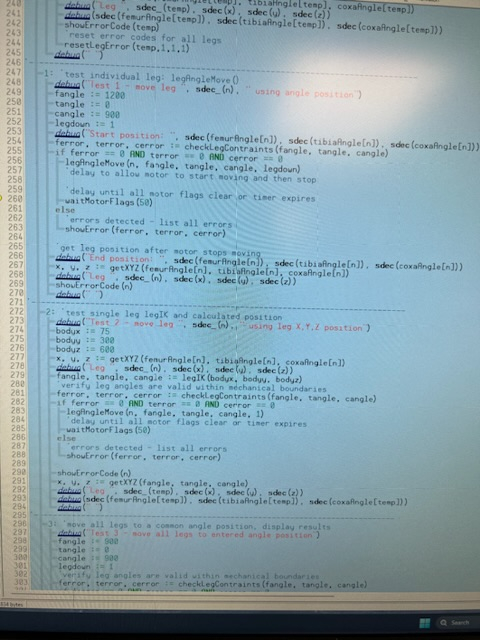
Here is a closer view of the new test code, it’s using a case statement to select the test to be run. There is some manual data entry items inside the test code to check for leg movement limits.
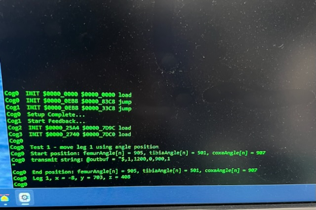
This is the debug window for test 1. It gives error conditions identified from either the P2 or P1 side of things along with initial values and ending positional data.
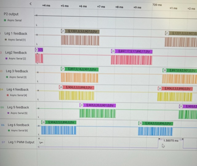
The logic analyzer is great for monitoring serial communications between the P2->P1 and P2->P1. I’m also checking the signal from the P1 to the femur’s HB-25 motor controller (not actually needed but I had an extra open channel1). This tool has been indispensable for tracking down communications issues and making sure the P2 variables are up to date. I also trigger it to run on a P2 to P1 movement command, then I can see the how long mechanical inertia takes between the movement signal, how long it takes for the P1 to notice the request, how long it takes for the motor to actually start moving the encoder, and after the motor is told to stop, how long does it take for the leg to actually stop moving. This information is used to set the PID controller values.
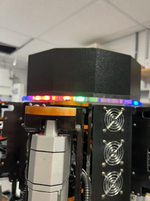
The RGB lights are great for knowing what the P1 controller is doing. Although the error messages come through, sometimes the message flies by unnoticed. However a flash of a red light on the robot is very noticeable and lets me know when to dig deeper or add additional error checking.
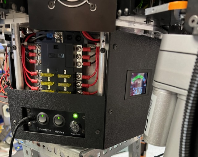
This doesn’t have anything to do with programming but it shows the leg controller fuses and power panel for the computers and motor controllers. The far right switch is the master power switch. You can also see the charger is plugged at this time. On the right side you can also see a Lascar programmable display used to monitor battery voltage. I installed a shunt wired into the negative battery terminal that someday I will connect up to the display to show actual current values. But for now the display is only showing battery voltage.
This automated testing idea is working out pretty good so far. It’s allowing me to run more consistent testing, run it faster, and get more consistent and meaningful data.
It has also shown a side benefit, by making more informative tests, I am able to tweak the code faster and figure out what works best. For instance, over the last couple of days I was developing a faster means of getting movement commands out, and with use of the logic analyzer I was able to shave an additional 150 msec off the loop time just by seeing the time interval between when a command is sent out by the P2 and how quickly the P1 controllers started to react to the command. I had been using 200 msec to allow the motors to react and start seeing confirmation via the P1 feedback system, now I know it takes on average 47 msec for this to happen. So the wait time could be dropped to 50 msec before starting to watch for when the motors stop moving.
I set up some tests for individual legs, checking the movement limits, checking movement using IK and full range of motion movement. Doing coordinated movement of 6 legs at at time using IK to control the leg positions. First step was just a coordinated movement of all legs by telling all legs to move up a given distance. I now have each leg starting their move within 10 msec of each other. I can improve that number by converting some of the IK and error checking routines to in-line assembly.
Tomorrow I start the leg down routines, very similar to moving the leg up but also have to take into account the leg down sensors and how the code will handle those messages. I’ve been testing everything with the robot on the test stand so for this I have to lower the body down enough the legs actually touch the ground. Time to re-attach the safety ropes again!
In the world of coordinated motion, this is all wrong, sorry. Those delays are eternities. If you are not close to sample accurate, the method needs reviewed.
The datasheet I uploaded explains how this stuff actually works. 😐
Nothing new here, been around since forever.
Highly recommended: pretty much anything authored by Dr. Jacob Tal (Galil Motion Control)
@Mickster said:
In the world of coordinated motion, this is all wrong, sorry. Those delays are eternities. If you are not close to sample accurate, the method needs reviewed.
The datasheet I uploaded explains how this stuff actually works. 😐
Nothing new here, been around since forever.
Highly recommended: pretty much anything authored by Dr. Jacob Tal (Galil Motion Control)
Also Chuck Lewin (Performance Micro Devices)
I have read the datasheet you cited and incorporated a few of the concepts into the P1 PID controller code. It did improve response time and reduced mechanical overshooting of the desired position.
What I was describing in my last posting is generating of a series of tests that ensure all the error checking and motor safeguards are working properly and generally reducing the time it takes to for me to re-do testing after code changes. I am not specifically working on leg coordination at this point. I just finished coding using Inverse Kinematics (IK) to raise and lower all legs at the same time. The only leg coordination needed for this was getting the 6 legs to start moving about the same time so the body more or less stays vertical. My initial coding to raise all legs resulted in each leg starting to move with a significant time delay between each leg starting its motion. I re-coded the movement routine so the movements all appear to start at the same time (I didn't think to get analyzer timing readings from before and after) and still return test data to the debug window.
During raising the legs, I was checking the timing between the P2 request for movement and how long it took for the P1 to receive and energize a motor (~20ms), then how long it took for the motor to actually make a movement where the encoder recognized an actual movement (~52ms - important to know this value because the feedback coming into the P2 still shows no movement until after that time), time of the actual movement itself is immaterial as that is dependent on the amount of angle change. The next important piece of information is how long after the motor reaches its position and power is removed does it take for the encoder to stop changing (~40ms). These timings are based on the P1 Feedback data which occurs every 3.7 ms and a command time of 2.1ms. So the timing data gathered is accurate to that 5.7ms notification period. In this instance only a single P2 motion command was issued to each leg.
Testing starts with moving a single leg, now it's moving all legs in a simple motion. This is learning how the legs react and how best to code the movements. Next test is moving a single leg in a straight line, this is where coordinating one movement to follow another and keep the appearance of smooth motion will start to come into play. The P1 leg software allows the legs to react right away to the last movement command even if the previous command hasn't completed, so it should be able to take advantage of some of that mechanical inertia to smooth out the motion. To figure out how to do that I will be incorporating information gathered from several sources (lots of downloads from various university graduate papers that discuss motion control) and seeing how that can be used in this particular setup. I have the advantage of being able to try out several methods and see which works best for this system.
One thing I have gathered from my research is that many motion control concepts are either purely theoretical or applicable to machines with very fast responses (using servos or fast response motors). My machine falls somewhere in between, the linear actuators are not particularly fast acting and have a lot of 'slop' in the internal mechanics. I engineered my part of the robot legs with fairly tight tolerances but there is still some play in the movements. So basically this is a hybrid machine that is going to require some 'tweaking' to get it to work the way I want it to in the end. I also don't have all the resources that these experts have available to them. The biggest limitation is that I'm basically doing this on my own, the only help I get is via this forum and people's comments. I have gotten lots of help in figuring out programming issues from several people which has really helped advance the coding to get where I am today. But I am missing the day to day collaboration that a team can bring to the table. I would love to have someone that I could have face-to-face discussions about how to proceed.
Your statement that my approach is all wrong is a little harsh at this stage but I will take that criticism and re-read my pile of papers on motion control and then see how I can use that in this situation. I will check the authors you cited and see what they have to say also. I appreciate your interest in my project and hope you continue to respond. Things like this help me see outside of the box and explore other avenues.
@The_Master said:
This is the first time I looked at this project.
What's this thing going to weigh when done?
Each of the 6 legs weighs in at 26 lbs so that’s 156 lbs there. I’ve never weighed the body section but I’d estimate its around 40 lbs. Total weight is probably close to 200 lbs total. The large linear actuators take up most of the weight and are rated to move 300 lbs, so plenty of power to move the robot, however this is not going to win any races!


Comments
I don’t mind getting comments and ideas, it makes me think outside of my own little box! I’ve used a lot of input from others over the years in the design. I have an engineering background so when I started this project I developed a ‘test’ leg to find out the weak points around the design and put in compensations to reduce or eliminate potential issues. At this point the legs have been tested mechanically quite a bit and have proven to be fairly robust so I’m not too worried about that part. Now I have to get the programming down right so it can start walking.
Finished 5 of the 6 leg mods, last leg is off the body and disassembled so I can hopefully finish it up tomorrow. Then I can get back to calibrating the coxa mechanism again.
It took longer than expected to complete leg coxa calibrations. I was calibrating the first leg when I found the motor could only rotate the coxa about 120º and not the expected 180º. That’s when I realized that the moving part of the leg was getting caught by the top part of the new cutout in the side supports. This didn’t cause any motor damage as the program stops the motor if the encoder output value doesn’t change when it should be changing. Turns out that with any weight on the legs the movable section could move up about 0.05” and get caught on the metal edge. Most of the legs were susceptible to this problem so that required removing the side supports again, widening the gap by 0.125” and then reinstall.
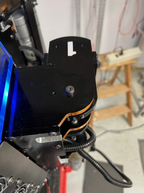
Once that problem was solved the actual calibration went fairly smoothly. I was able to test each leg individually and made sure the leg moved freely from 0º to 180º on each coxa. In some cases various motor or sensor wires got pinched which stopped the leg from moving but that was fixed using zip ties to keep the wires in the proper locations.
Today I hooked up the logic analyzer again and started controlling the legs via the P2 master computer. So I’m finally back to where I was at a couple of months ago! Anyway, I am coding to move a single leg tip in a straight line based on input from the direction the hexapod body is moving. This involves a bit of math again as the 6 legs are arranged every 60º around the body and if using the body as the primary coordinate (x,y,z) system, body movement has to be then converted into coordinates that each of the individual legs can understand.
Another part of the programming is getting the leg tip to move smoothly as each motor has a different runtime as it gets the leg tip into position. Right now the leg tip is moving 10mm in the X and Y axis before stopping and getting the next position so it isn’t moving as smoothly as I would like. I will be experimenting with different movement increments, checking when each motor has stopped running, and using timers to find the best movement algorithm. The logic analyzer is great for this work as it can pinpoint when specific processes start and end. Still working with a single leg right now, will add a second leg into the mix once some of these questions have been answered.
I’m still totally crushing on this thing. I cant wait to see it move!
Not a good day! Started up the computer and installed the latest version of PropTools. Ran the spin2 code and got an error that debug communications was lost. Tried again, same result, uninstall and try again, same thing. Uninstall and then re-install the version I had installed earlier, now it says the same thing. To top it off, the Logitech mouse stopped working, had to find a wired mouse to get going again. Come to find out the computer bluetooth is OFF and according to all the troubleshooting measures I have run, it isn’t even installed. Located a Logitech bluetooth adapter that plugged into a USB port, got the mouse running again.
Tried PropTool again, same problem. So I decided to run the latest version of FlexProp (I’m a Patreon so have access to the newest version) and it isn’t running a debug terminal at all, although the previous leg program did run and the leg was moving. Just no debugging data to analyze.
Next stop was SimpleIDE, it had issues too. So after a few hours of beating my head against the wall it was time to take a break and shut everything down for a while, get back tomorrow with a fresh start.
Grrrrrrr!
Back to the computer today, now the built-in bluetooth is working again so I was able to remove the logitech dongle and get my mouse working right!
I installed the newest version of the Prop Tool (2.9.3) but I get a Debug Communications Lost error so nothing shows up on the debug window but the program is running as the robot is moving a leg according to my last test. I found this error is occurring on all the 2.9.x versions of the program so I had to revert back to 2.6.3 to get the debug working correctly. Unfortunately this means I can't use the new single stepping ability but right now I don't really need it for the tests I am running.
So right now I am testing using leg1 and having the leg tip move in a straight line. The code works but the movement is not as smooth as I would like. I think I need to go with a smaller step value (set at 5mm now) to get it right. The code looks at the X,Y, Z leg coordinates and divides each axis up by the step value, then it advances each axis in discrete steps to the end point. A better way may be to break up the hypotenuse (the distance the body is attempting to traverse) into steps, calculate the the X, Y step values from that instead. Have to think about that some more and figure out how to code it (this may actually be a simpler way of doing this).
I plan on doing some more videos once I get some more progress. I'll also go into more detail on the math involved with moving a leg in a straight line and then moving all the legs together.
If I understand what you mean, those way-points need to be discreetized, based on time (trajectory generator).
I recently learned that Kuka Robotics have an update rate of 14ms (don't know where that particular number comes from). I typically run at half the rate of the PID loop. So, if my PID runs @1KHz, the trajectory generator runs @500Hz.
Craig
With some great insight from Jeff Martin, the debugging error has been solved. Turns out that the Rev A & B versions of the P2 Edge board TX pin is not pulled high and ends up throwing the debug communications error. I swapped the Rev B board for a Rev D version and it started working! Jeff said addition of a resistor to the TX line can fix the problem, I a waiting for a response on recommended resistor size and installation location so I can fix the 2 earlier edge boards.
So now that I can run version 2.9.3 of the Prop Tool, I was able to start using the polxy() method instead of my workaround.
So running a simple test where I tell a leg to lift up 100mm and measure the actual distance moved. The actual distance moved was 108mm so there is a 8 mm discrepancy to look into. With different lift distances I get smaller errors: 10mm -> 2mm overshoot, 50mm -> 4mm overshot. The error progression is linear so it is either a calibration issue, the PID overshooting the target value, or additional mechanical movement after the target is reached.
I noticed when I went with a 150mm lift, I got strange results, the tibia moved to 8.9 degrees with no upward movement of the femur. The command sent was for the femur to move to 20.5 degrees which is outside the allowable range. The P1 controllers picked up the bad command, sent an error message to the P2 but the P2 error debug didn't pick it up other than to light up a red error light. So something else to track down!
Thanks for the information, I'll use this info once I track down these other errors!
As previously stated; you need PD, not PI. P is the spring, D is the damper. I is a no-no unless you need zero error at steady state
Craig
Another good day (mostly) on the robot. Today I worked on a couple of simple routines that allowed me to raise and lower the robot body by sending the same command to all 6 legs at the same time. It mostly worked but I had a few minor glitches that need to be sorted out. I also need to re-attach my safety rope to the body for those situations which don’t go quite right! I put together a short video showing the robot movements, the way the RGB lights are using for troubleshooting and the debug window which is where most of the troubleshooting is coming from. As you can see in the video, I extensively use the debug window to capture starting positions and the end positions of each leg and the input coming back to the P2 from the individual P1 controllers.
https://youtu.be/EMEnAwUO_Ls
I’ve been adding more code to catch errors but you can see in the video there are still some bad commands coming through that I have to find the source and make corrections.
I’m not sure you could see it in the previous video but the code was basically telling each leg to move the same amount in the downward direction. To do this the P2 takes the current X, Y and Z position for the leg, uses IK math to convert that to motor angles. The resulting angles are checked to validate they are in the proper range. If no errors, then the resulting movement command is transmitted to the corresponding leg. Then it repeats this process for the next leg. What I noticed is the the very slight delay in the start times for each leg’s movement. The logic analyzer shows about a 57ms delay between P2 transmit cycles, so around 300ms for all 6 legs.
I think delay is also the cause for the problem I found on leg 4 after the program ran, leg 4 leg sensor was no longer touching down. That’s because after leg 4 actually ‘touched’ the ground, leg 5 and then leg 6 drove their legs down until their sensors sensed the ground. This most likely resulting in lifting the robot body just enough where leg 4 sensor wasn’t firmly on the ground.
Thinking it over, the goal would be to minimize the delay between leg motor starts. The one way I can think of is to get all 6 leg movement commands figured out and then transmit them without the delay while the P2 figures out the next leg’s position. This way all the calculations are made up front for a leg move and then the P2 is just transmitting movement commands until told to stop or new parameters are entered.
For raising and lowering a leg that is pretty simple, I just need a buffer for each leg that holds the up or down movement command. But it gets more complicated if the leg is to make a step, there are potentially quite a few interim movements between the start and end positions. The array size could get large and unwieldy. I’ll try a simple test just like the current code where I just raise and lower the legs, see how much faster the P2 can transmit that way. I can also increase the P2->P1 transmit speed (set at 57600baud) and see how that goes. I picked this baud rate back when I was using a P1 as the master and it was about as fast as I could get reliable data between the units at that time.
Coordinated motion over a serial bus. All axes perfectly in sync @2KHz.
P1 can easily outperform the picsrvsc.
FWIW: I went with this arrangement but using a 3K3 pullup. P2 talking to four RPi-Picos. Pico Baud limit is 921.6 K. I don't need this speed but used it to test for reliability
https://forums.parallax.com/discussion/172266/multi-drop-serial#latest
First I changed the transmit and receive speed on the P1 controllers, increased the baud rate to 115200, no errors identified either receiving or transmitting at this speed. Haven't tried going higher, not sure that would improve anything anything although the interval between output P1 feedback went from every 6.68msec to 8.7msec just because the data transmits faster.
When manually testing this speed change out on leg 1 (I have the computer physically linked to leg 1 and running it in manual mode, all other legs are still in automatic mode which is waiting for a command string from the P2 module - no program is running on the P2 at this point), leg 6 suddenly moved to the 0 degree position on the coxa, causing some interference with the leg 1 movement tests I was performing. As I wasn't sending any commands to leg 6, nor was the P2 master running any program, this indicated some type of problem. I set up some movement scenarios and discovered that now that the movement range for the coxa goes from 0 degrees to 180 degrees, it was possible to 'accidentally' have a 0 sent as a valid movement command for the coxa. The P1 code brings in the movement data, extracts femur data, sends that to the femur PID, next it extracts tibia, then coxa. If the coxa value is missing (such as an incomplete command string goes to the leg), then a 0 can be sent to the coxa PID, this wasn't a problem when the minimum coxa value was 32 degrees.... Changed the P1 code to extract all the data from the P2 input string up front, if any data is missing that sends a -1 value which prevents any of the motors from being activated and sends an error code back to the P2.
I also re-introduced transmitting a leg number in the movement string to help prevent spurious input commands. This was part of the original communications design when all P1 receivers were tied together. When I rewired the system so each P1 was wired directly from a P2 output, I removed the leg number data as it appeared to no longer be needed.
Of course any changes like this introduces other issues that have to be tested, errors found, code fixed, repeat! I think I may have broke the HB-25 motor controller startup code somewhere, it's requiring the motor controller to be cycled off and back on again for them to actually work. Had to search on-line for the manual since I couldn't find it on their website anymore. So going over the manual to see what I might have accidentally deleted or changed in the P1 startup code.
Mickster - Thank you for the information, I'm still processing that in my mind and trying to figure out how that could be used in my situation. I read the PIC-SERVO manual, have to see how that information can be used.
Mickster - I've read the PIC SERVO document a few times now and got some ideas try out.
I did a couple of mods to the Femur PID code and discovered a coding error that's been there since I first typed it in. The results of the error were hidden but caused the PID loop to overshoot in some circumstances. I corrected that and went into a in-depth review of that code to see if there were other hidden problems or things that got added to the code but were no longer needed. I did try removing the integral portion of the PID controller but got much worse response so put it back in again. I did change the Pi value to divide it by 8 to reduce its overall effect. That resulted in a faster response without an endpoint overshoot. The derivative (Pd) value I'm still fooling around with. One of the ideas from the PIC SERVO document was an option they have where the you look further back in time at earlier error values which can inflate the derivative which would have the effect of toning down the Kp value. I have to figure out a way to retain those earlier error values, right now I only save the immediately previous error for use in the derivative.
Next I will finish testing the code modifications and then dump it to each leg controller. Then I can get back to working on the P2 again (assuming the P1 code changes work the way they are supposed to once the leg controllers aren't in manual mode!)
Anyway, its more fun playing on the computer in the basement than the cold wet day that Michigan has for me outside!
Hi Bob,
Derivative for me is typically 5 to 10 times the proportional. In 40 years, I have never had success with integral, during motion. It resulted in huge machinery dancing across the floor
I played with the SRD (I just used a 4-element array, shoved the latest D into the first element, shuffled the others down and discarded the oldest value). Didn't need it though because my encoder line-count is either 2048 or 4096 (8192 or 16384 quad counts/rev).
I had no idea that you are in MI


This was my CNC Tube-Bender factory in Wixom 48393:
Cheers!
Craig
I’m on the other side of the state from you, in Saint Joseph, MI. I live about 6 miles from Lake Michigan and all its fun weather it throws our way!
I used to have to adjust PID controllers in my Navy days and taught PID controller theory at power plants (among other things!). However this is the first time I’ve written software to do what I did with analog in the past. It’s been a learning experience but I’ve had fun even when it didn’t work the way I envisioned it.
The resulting PID code has been tweaked quite a bit over time and some older ‘fixes’ have become un-needed at best and potentially harmful at worst. I’ve cleaned up the code by going line by line, commenting out portions of code that don’t make sense anymore and then running some quick tests to ensure there wasn’t a hidden reason for it. My program notes have become better over time so that helps a lot in determining the code usefulness.
Today was just too nice to be inside so planning on some evening programming/testing later.
Oh I am still a fan of the analog stuff. I frequently come across one of my late 1980s machines. Brush-type motors, tach feedback, potentiometers on the drives....Just like new, never been tampered with and they've been ridden hard.
Today, a technician can't do a darned thing without a laptop and the setup software usually sucks.
My aim is to make everything simple and fixable again....it's a conspiracy I tell ya
The traditional suppliers are really screwing over the industry with the BS.
I have dubbed my P2 controller "MTTR ZERO-H" (mean time to repair, zero hours).
It's happening
Craig
Update time!
The last week has been spent testing the PID and communications mods and fixing any new problems they introduced. I found I needed to re-calibrate the 3 axis encoders again so after a couple of days doing it manually and then getting inconsistent outputs, I decided to write code to assist in the calibration. Once I got that entered and fixed, calibration is going a bit smoother. Basically I have to drive a motor to its extreme limits and get the encoder value at that point. The tibia motor was proving to be a bit troublesome, at the extreme minimum angle, the tibia was at a negative angle. However the tibia linear actuators can be manually adjusted by disconnecting them and the output shaft can be screwed in and out to lengthen. It takes some trial and error to get the shaft to the right length so that the tibia angle is = 0 degrees.
Finished up leg #1, pushed the program updates to EEPROM on the P1, got about halfway through leg #2.
Successfully calibrated and updated all 6 legs. Back to testing the legs using the P2 Edge module again. Starting with checking each individual leg (ensures commands are being transmitted by the P2 and the P2 gets the appropriate feedback from the P1 controllers). Then its back to where I was before I was before I diverted back to coding the P1 controllers.
As i was planning out my next steps, one thing I realized is it would be possible that over several steps the legs on one side of the hexapod could gradually become higher or lower due to the rounding in the math routines. I think it would still be able to move but would grow increasingly lopsided until a leg reaches a hardware movement limit. To counteract this, I need the P2 to monitor the inclination of the axis so corrections can be made to the gait. Parallax has several tilt sensors, I have several of them in my parts drawer! The best one for me looks to be the LIS3DH 3-Axis Accelerometer with ADC module. It has some P2 code I can try out and see what kind of output it creates so I can figure out how to incorporate it into the robots code. Could be a fun little diversion when I get tired of testing…..
Thats inclinometer idea is interesting. I assume there would be one in the body to serve as a master reference to compare the legs to if the whole beast was on a slope? And if this was true, is there a reason you couldnt use each legs incline sensor for absolute position on-the-fly?
Totally crushing on your mischief here!
You are right, the idea would be to install the inclinometer to the main robot body. The legs don’t have any tilt sensor on them, just magnetic encoders and the leg down sensor. This will also be useful whenever I get to the point where it’s time to teach it to walk up stairs.
Had an interruption in testing the P2 side of the robot, I found that errors generated by the leg controller were not clearing so the P2 isn’t sending the next set of instructions. Since I’m checking for quite a few error conditions, the P2 side to acknowledges the error and either ignore it if it isn’t important in the current condition or acts upon the error. But I didn’t build in a way to reset an error from the P1 leg controllers. So I came up with an error reset mechanism that allows the P2 to selectively reset individual errors or all errors coming from a leg controller.
So after that delay, I’m back doing the testing of the leg controllers. This testing is basically manually running a series of code routines that send different commands to each leg and record the results. It’s a fairly lengthy process and when an error is encountered then review of the debugging output listings is needed to determine what is happening and figure out a correction. Then it’s time to start testing over from again. I’m thinking of seeing how I can automate some of the testing to take out some of the tedious portions of the process.
Basically these are the tests that I do on the P1 leg controller side (this performed mainly on a single leg as all legs run the same code - if a calibration is needed then there are more steps performed on each leg individually):
Determine amount of positional error after each axis completes a movement
The P2 side testing adds a few more checks:
Send basic movement commands to each leg axis (femur, tibia, coxa). this checks the P2 to P1 communications
I want to especially simplify/automate the P2 testing as it takes the most time to perform. Usually the initial tests go fine, its the straight line part that has some type of failure or undesired problem that requires digging into the debugging info and code more deeply.
Today is a gray, cold, and rainy day in Michigan, good day to spend in the basement coding!
After my last posting about figuring out how to make the testing process simpler, I started work on coding a more straight-forward approach to the testing that minimized the amount of scrolling through the code, commenting out and in sections based on what I wanted to test for at that moment, and also get some consistency in the output display data so I’m not searching for every nugget of information that might be useful.
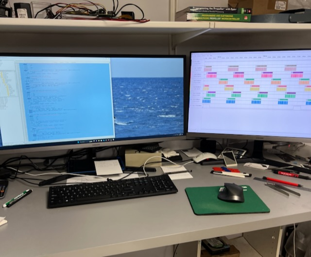
Here is my programming setup, I added another large screen as I typically have the Prop Tool and debug window open along with the logic analyzer, Parallax forums (for whatever my last search turned up, and any other misc screens needed.
Here is a closer view of the new test code, it’s using a case statement to select the test to be run. There is some manual data entry items inside the test code to check for leg movement limits.
This is the debug window for test 1. It gives error conditions identified from either the P2 or P1 side of things along with initial values and ending positional data.
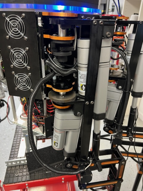
The logic analyzer is great for monitoring serial communications between the P2->P1 and P2->P1. I’m also checking the signal from the P1 to the femur’s HB-25 motor controller (not actually needed but I had an extra open channel1). This tool has been indispensable for tracking down communications issues and making sure the P2 variables are up to date. I also trigger it to run on a P2 to P1 movement command, then I can see the how long mechanical inertia takes between the movement signal, how long it takes for the P1 to notice the request, how long it takes for the motor to actually start moving the encoder, and after the motor is told to stop, how long does it take for the leg to actually stop moving. This information is used to set the PID controller values.
The RGB lights are great for knowing what the P1 controller is doing. Although the error messages come through, sometimes the message flies by unnoticed. However a flash of a red light on the robot is very noticeable and lets me know when to dig deeper or add additional error checking.
This doesn’t have anything to do with programming but it shows the leg controller fuses and power panel for the computers and motor controllers. The far right switch is the master power switch. You can also see the charger is plugged at this time. On the right side you can also see a Lascar programmable display used to monitor battery voltage. I installed a shunt wired into the negative battery terminal that someday I will connect up to the display to show actual current values. But for now the display is only showing battery voltage.
This automated testing idea is working out pretty good so far. It’s allowing me to run more consistent testing, run it faster, and get more consistent and meaningful data.
It has also shown a side benefit, by making more informative tests, I am able to tweak the code faster and figure out what works best. For instance, over the last couple of days I was developing a faster means of getting movement commands out, and with use of the logic analyzer I was able to shave an additional 150 msec off the loop time just by seeing the time interval between when a command is sent out by the P2 and how quickly the P1 controllers started to react to the command. I had been using 200 msec to allow the motors to react and start seeing confirmation via the P1 feedback system, now I know it takes on average 47 msec for this to happen. So the wait time could be dropped to 50 msec before starting to watch for when the motors stop moving.
I set up some tests for individual legs, checking the movement limits, checking movement using IK and full range of motion movement. Doing coordinated movement of 6 legs at at time using IK to control the leg positions. First step was just a coordinated movement of all legs by telling all legs to move up a given distance. I now have each leg starting their move within 10 msec of each other. I can improve that number by converting some of the IK and error checking routines to in-line assembly.
Tomorrow I start the leg down routines, very similar to moving the leg up but also have to take into account the leg down sensors and how the code will handle those messages. I’ve been testing everything with the robot on the test stand so for this I have to lower the body down enough the legs actually touch the ground. Time to re-attach the safety ropes again!
In the world of coordinated motion, this is all wrong, sorry. Those delays are eternities. If you are not close to sample accurate, the method needs reviewed.
The datasheet I uploaded explains how this stuff actually works. 😐
Nothing new here, been around since forever.
Highly recommended: pretty much anything authored by Dr. Jacob Tal (Galil Motion Control)
Also Chuck Lewin (Performance Micro Devices)
I have read the datasheet you cited and incorporated a few of the concepts into the P1 PID controller code. It did improve response time and reduced mechanical overshooting of the desired position.
What I was describing in my last posting is generating of a series of tests that ensure all the error checking and motor safeguards are working properly and generally reducing the time it takes to for me to re-do testing after code changes. I am not specifically working on leg coordination at this point. I just finished coding using Inverse Kinematics (IK) to raise and lower all legs at the same time. The only leg coordination needed for this was getting the 6 legs to start moving about the same time so the body more or less stays vertical. My initial coding to raise all legs resulted in each leg starting to move with a significant time delay between each leg starting its motion. I re-coded the movement routine so the movements all appear to start at the same time (I didn't think to get analyzer timing readings from before and after) and still return test data to the debug window.
During raising the legs, I was checking the timing between the P2 request for movement and how long it took for the P1 to receive and energize a motor (~20ms), then how long it took for the motor to actually make a movement where the encoder recognized an actual movement (~52ms - important to know this value because the feedback coming into the P2 still shows no movement until after that time), time of the actual movement itself is immaterial as that is dependent on the amount of angle change. The next important piece of information is how long after the motor reaches its position and power is removed does it take for the encoder to stop changing (~40ms). These timings are based on the P1 Feedback data which occurs every 3.7 ms and a command time of 2.1ms. So the timing data gathered is accurate to that 5.7ms notification period. In this instance only a single P2 motion command was issued to each leg.
Testing starts with moving a single leg, now it's moving all legs in a simple motion. This is learning how the legs react and how best to code the movements. Next test is moving a single leg in a straight line, this is where coordinating one movement to follow another and keep the appearance of smooth motion will start to come into play. The P1 leg software allows the legs to react right away to the last movement command even if the previous command hasn't completed, so it should be able to take advantage of some of that mechanical inertia to smooth out the motion. To figure out how to do that I will be incorporating information gathered from several sources (lots of downloads from various university graduate papers that discuss motion control) and seeing how that can be used in this particular setup. I have the advantage of being able to try out several methods and see which works best for this system.
One thing I have gathered from my research is that many motion control concepts are either purely theoretical or applicable to machines with very fast responses (using servos or fast response motors). My machine falls somewhere in between, the linear actuators are not particularly fast acting and have a lot of 'slop' in the internal mechanics. I engineered my part of the robot legs with fairly tight tolerances but there is still some play in the movements. So basically this is a hybrid machine that is going to require some 'tweaking' to get it to work the way I want it to in the end. I also don't have all the resources that these experts have available to them. The biggest limitation is that I'm basically doing this on my own, the only help I get is via this forum and people's comments. I have gotten lots of help in figuring out programming issues from several people which has really helped advance the coding to get where I am today. But I am missing the day to day collaboration that a team can bring to the table. I would love to have someone that I could have face-to-face discussions about how to proceed.
Your statement that my approach is all wrong is a little harsh at this stage but I will take that criticism and re-read my pile of papers on motion control and then see how I can use that in this situation. I will check the authors you cited and see what they have to say also. I appreciate your interest in my project and hope you continue to respond. Things like this help me see outside of the box and explore other avenues.
Bob Sweeney
This is the first time I looked at this project.
What's this thing going to weigh when done?
Each of the 6 legs weighs in at 26 lbs so that’s 156 lbs there. I’ve never weighed the body section but I’d estimate its around 40 lbs. Total weight is probably close to 200 lbs total. The large linear actuators take up most of the weight and are rated to move 300 lbs, so plenty of power to move the robot, however this is not going to win any races!
Bit cold, dude. My .sig expresses how I feel about this thread.