Today was spent performing a series of tests to make sure the new serial setup transmits correctly to the legs from the P2 master.
First test was the simplest, just send a movement command to a single leg. After a couple of false starts I got that running with no issues (Yay, first leg movement using the new serial setup!).
Next step expanded that test by sending a movement command to all legs at the same time. The leg controllers have their P1 pins wired together so data the P2 transmits 6 individual data packets out pin #5 ($,1,900,0,900,1,13 $,2, 1,900,0,900,1,13 and so on). Each P1 listens for the start char “$” and then if the delimiter (“,”) is followed by its leg number (1 through 6), it then copies the string up to the 13 (return char) and then acts on the string. The legs ignore any commands coming for the other legs.
When I sent a single command down the wire, the correct leg responds, proving the other legs knew to ignore the command.
Sending the command out to all 6 legs at the same time, I saw a problem. Initially only legs 1 and 4 responded. Debugging indicated that although correct outputs were generated by the P2 master, only the leg 1 and 4 were actually transmitted to the legs, leg 2, 3, 5, 6 commands were not transmitted.
I reviewed the serial demo which used a txflush() after transmitting. After adding this method I got 4 to 5 legs responding each time, but the one(s) not responding were different legs each time. Sending the same command a 2nd time resulted in the leg(s) that didn’t initially move would move to the right location. I added a 100ms wait between each leg transmitt which got 5 out of 6 responding but again, still had different legs not responding each time. Next step was changing the baud rate on the P2->P2 line from 115_200 to 57_600 on the transmitt line to see if that helps. Not so much as now nothing is responding which is where I left it after much head scratching. My next check is to put a logic analyzer on the output line from the P2 and see if I’m getting any garbage out of the P2. As I’m sitting here typing this another idea comes to mind that instead of sending 6 separate strings from the P2, maybe combine them into a single string and see how that works.
Bob,
I like the idea of using a single string to address all six legs. It seems to me that I have seen P1 code that would allow parsing that string by segment numbers like a basic midstr command. That might solve the problem as each leg gets the section of the string it needs.
Wishing you continued successes.
Jimj
Thinking out loud here: What about turning the address portion into a bitmask. Each addressed device looks at its corresponding bit in the address byte to decide if it needs to even pay attention to the message. Then, within the string, there is a “slot” for each device to “look at” for the command/value info being sent to that device. This makes the entire command string a fixed number of fields and makes the comm line more like a bus. This could make it capable of nearly any topology (series, parallel, star, tree, ad hoc). Replies from each leg would probably need to be polled, but depending on your needs this may not be a big issue.
Thanks for the ideas everyone!
Later last night I was in my favorite chair thinking about the problem, I had another thought about what to try out. I’ve been trying to run this ‘network’ the same way I did when the master computer was a P1 and I was having issues with the processor speed, number of available cogs, available output pins, available memory, and limitations of some of the P1 objects I was using. Now that the P2 is in the mix most of those issues aren’t an issue anymore.
The current configuration has 6 ports, P1->P2, set up to receive data only (no transmit pin configured). A 7th port is used to transmit P2->P1 data. Since I have an abundance of P2 ports, why not just use the 6 ports ports to send and receive? The code on the P1 side can stay the same (although it wouldn’t need a leg number value to parse which helps with speed). The transmit code on the P2 side is easily modified to send out over separate ports instead. With this setup, any command coming into a P1 controller is data to act on. I don’t think this will make a difference on the P2 side of things as far as speed is concerned.
Looks like I have some port re-wiring, coding, and testing to do today!
Rewired the P2 to P1 controller serial setup. Pins 4 through 15 on the P2 are wired to each of the P1 RoboPi boards on pins 1 (rx) and 2 (tx).
No changes were made to the P1 code as I am still using the original serial string setup for now. The P2 code required a few changes, 6 ports that were only receiving P1 data now have a tx pin assigned.
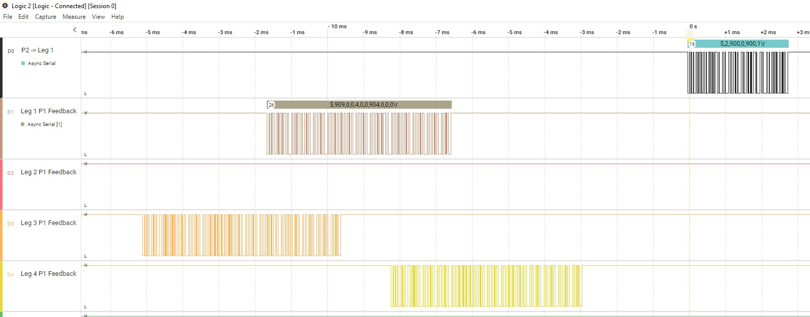
Testing the ports consisted of first reading the data from the individual P1's which was successful. Next step was transmitting a movement command to Leg 1. In this case Leg 1 failed to respond. To make sure data was being sent correctly a logic analyzer was connected to P2 to leg 1 transmit pin. The analyzer showed that data in the correct format was being sent to the leg controller. (see the attached file).
Now I have to figure out why the P1's aren't responding to the movement command. I have verified the baud rates are the same (57600) on the P1 and P2. Wiring was checked several times and it all lines up as expected. The movement command format from the P2 is showing up correctly on the analyzer. Most likely it is something simple that I a overlooking... Back to work now
Bob
EDIT: Not finding the problem so far. The movement command string is good but the leg controllers are not recognizing it. Although I didn't change anything with the leg controller code, I will get back in there and test the controllers and see what is going around in there. There is on thing that is puzzling me, the commands out of the P2 have a '\r' showing on the analyzer at the end of the string where I am sending a value of '13' for CR. This could just be the way this analyzer's ascii displays the CR value. The P1 outputs also show the same \r instead of CR but the P2 is handling that OK. I don't think this is the problem but it doesn't make sense either. Time for a break away from the computer to mull this over.
I once spent the better part of a day chasing something like this. Turned out the data was perfect… except the serial line idle state on one side was inverted compared to the other. (-facepalm!-)
Gathering more information for troubleshooting the serial communications between the P2 to P1 leg controllers. I re-ran all my tests from yesterday with the same results. The logic analyzer is still showing the P2->P1 commands as being transmitted correctly but none of the legs are responding to the request.
Next test was to set the P2 to repeat the movement request to the Leg 1 controller on a 1 second cycle. I used the analyzer to verify the request was being sent to the Leg 1 controller on a loop. Next step was moving the prop plug from the P2 over to the leg 1 controller. I put the code in manual mode and entered a movement command manually via the PST, this worked as expected and the leg moved to the new position. I put the code back in automatic mode and resent the code to the controller. This time the leg moved to the position being sent from the master. I was able to repeat this by manually moving the leg to various positions and as soon as I recompiled the controller in automatic mode (where it listens for input from the P2), it would move to the P2's requested position.
This proves the data is being sent and received by the leg controllers but they are not acting on the data. Next step is crunching through the P1 code to figure this out (too bad DEBUG doesn't work on P1 code - I still have a lot of embedded debugging print statements to the PST that are active when in manual mode). Slowly narrowing this problem down!
Edit: On the P2 side I wrote a routine to change the femur position by 2 degrees every second between 60 and 120 degrees. Same results as above except I kept the leg 1 in auto mode and every time I re-compiled the P1 code, the leg would move to another position but only made the one move. It appears the P1 is seeing only one input command at a time and ignoring all the rest in this situation. Continuing to try and narrow down the bottleneck in the P1 code.
During troubleshooting I found that putting a 5ms delay right after the code that reads the incoming data from the P2, then the leg responds as expected to each incoming P2 move command. If the delay is less than 5 ms, it stops working again. Based on this observation, it appears that the code reading the incoming P2 data and stuffing the data into a buffer needs the extra time to complete the task as the next task is extracting the comma delimited angle data from the buffer. Either way, it is working again using the new serial object!
With the leg moving again with the P2 input commands I was able to see some things from the logic analyzer that lead me to make some more minor P1 code changes. Now that the P2 is directly wired to each P1, sending the leg # data isn't really necessary so I commented out the code that looks specifically for the leg. I will use the same data format for the string coming into the P1 (numbers 1...6 were leg numbers, 7, requests leg calibration, 8 is setting motor speed, and 9 is an emergency stop) and made a few other minor P1 changes as long as I was going to have to upload the program to the EEPROM's on all the leg controllers.
I want to finish up the P1 code changes and test them out individually on each leg before I get back to the P2 coding
Still working on the P1 coding, the logic analyzer has become very useful at this point. I set the P2 in a loop to output to Leg 1 a changing femur position between 60 and 120 degrees and then back down to 60º in 2 degree increments with 500 ms between each command. The P1 controller is sending data back to the P2 every 12ms the leg position. Per the analyzer, after the leg controllers receive a movement command, it takes about 20 ms for the leg to physically start to respond (based on when the P1 feedback shows movement). Typically a 2º femur movement takes about 100 ms to complete the movement and show a steady position. This also captures any leg movement errors by flashing the RGB lights so a red flash indicates something didn’t go the way it should have. Having these additional tools has helped me to identify some problems that aren’t apparent when manually entering movement data
Problem 1: Femur should be moving 2º each command, sometimes it doesn’t move because it moved too much the previous time and overshot the desired position. This is a PID calibration problem
Problem 2: Even though the P2 is only requesting movement of the femur, the tibia occasionally moves. When it does move, then it starts oscillating around the correct position. This is really 2 issues, PID calibration causing an overshoot but more importantly, what could possibly cause the tibia to move in the first place?
Problem 3: Coxa isn’t moving but a red RGB indicates an error condition is occurring. I believe it is related to the code that checks if the encoder isn’t responding and then stops motor movement. But like the tibia, there isn’t a move command going to the coxa so this part of the code should not be responding.
Problem 4: Tibia RGB flashes red sometimes, I think it is a similar issue as in Problem 3.
So I’m going to work my way down this list and fix the issues as they come up. Sure that a few other items will show up in the meantime. I do need to figure out a faster way to calibrate the PID loop, right now there are 3 main variables that impact the PID and calibration means increasing one value at a time until the leg tends to oscillate, back it back down and then do the same for the next variable. This takes a lot of time as there are subtle effects between the variables also so I go back and forth several times.
I started working on problem #4 first (I know, out of order but it captured my interest the most). Reviewing the coxa movement initiation code and PID I couldn’t figure out what would cause the PID loop to be entered without a movement command. I started a debug display of the input string from the P2. Here I discovered that occasionally the P1 wasn’t capturing all the P2 serial data so instead of “$,900,0,900,1”, it might come out as “$,900,0,9”. This prompted a review of the code that receives the serial and appends the data into the string. I was using rxcheck() for receiving data so I changed that to rx() instead. With this code change the reliability of the input string was improved greatly and the incidence of missing data was almost eliminated. This solved Problem #4, #3, and part of #2.
Problem #1 (and #2) were directly related to tuning of the PID loops for both motors. I tuned these using information I read about tuning PID loops in general. Increase the Kp value until the output oscillates and then back it down until it doesn’t. Repeat the same for the ki variable. I did this again but came up with the same kp/ki values as before. Now this is where the information on the logic analyzer came in very handy. Data from the P2 was coming in every 500ms and the P1 was sending actual position information along with motor direction data back to the P2 every 12 ms. Starting out with a P2 command I could see that the motor started to respond after around 15ms. I counted the number of P1 feedback pulses that showed power to the motor. When the P1 feedback showed the motor to be OFF, I then watched the motor angle change until it stopped changing. This time is how long it takes for the motor to physically stop. For moving 2º, the femur took about 100ms more to actually stop. In many instances although the motor was stopped within 0.5º of the requested location, inertia moved the femur another 1º-1.5º more.
I used this information to manipulate the Kp, Ki, and deadband variables. Increasing the deadband value to 1º tells the motor to stop sooner and then I use the inertia to glide closer to the actual requested value. By using the analyzer and watching the P1 feedback after a P2 command, I was able to find better values which ended up improving the response.
I was able to repeat the same system to tune the tibia motor for the same improvement. The coxa was a bit different as it has a custom gearbox including the one built in to the motor so when the motor stopped, there was no additional inertia movement no matter what variable changes I made. In the end I kept the values all the same.
Next step is verifying the code changes work on each leg and then loading the P1 EEPROM’s with the new program.
I think the next thing on the agenda is to see how well a single leg tip does when the P2 tells it to move in a straight line. This will test out the new Inverse Kinematics equations and code. I described a while ago that I found a mistake in my geometry which might explain some of the inconsistencies I saw the last time I was at this point. Since then I’ve added the magnetic encoders, switched to the P2, using integer math for all IK calculations, and fixed the geometry issues.
Spent more time calibrating the legs after I wrote the last entry. As noted earlier there was a lot of leg oscillation in the femur and tibia movements when the P2 was sending commands to move the leg in 2 degree increments for these 2 motors. I found that if I put some tension on the leg by lifting it up while it was moving, the oscillations mostly went away. Tension in the upward direction is what the leg would normally be experiencing if the leg was supporting the weight of the robot. I tuned the PID to mostly remove the oscillation with tension on the leg. In cases where the leg has to be picked up I am looking at a mechanical solution such as putting a torsion spring on the femur and tibia pivot points to provide the tension. I wasn't able to locate a suitably sized torsion spring so I will be ordering spring wire and winding my own springs.
Of course all this experimentation reveals other problems/issues to solve which has been taking up the rest of the time. I fixed one issue with a code fix which broke another part of the code (femur wouldn't respond if I told it to got to 120 degrees, it worked for all other angles, just not this one (harder to find this one as it was a change I put in quite a while ago).
To start testing moving the leg in a straight line, I wanted to make sure the Inverse Kinematics code was working right first. A quick test is to startup leg controllers, retrieve motor angle data. The P2 converts this angle data into an x/y coordinate. Now I feed that same coordinate back into the P2 IK routine and theoretically I should get the same angle data. Well, that didn't happen. So here is where the DEBUG statement in Spin2 comes in real handy to watch the calculations (including the in-line PASM code) and compare each step to the calculations I did by hand using a calculator. Tonight I finally got the hand calculated values for the angles to match the coded values. I need to run a few more leg positions through the calculator and make sure I didn't miss anything. I also have to put in some error coding to catch situations where input IK values result in a bad output.
Unfortunately there isn't much to video or take a picture of other than screen shots. I'll post the IK code once I verify its working right for more leg positions.
Hi Bob,
I confess to have only just looked at this (huge) thread for the first time. Mainly because a "robot", here, usually means a rickety open-loop articulated arm or something on wheels that, for me, is more accurately described as an AGV.
This means that I've only glanced at the last few posts but I see that you are working on something really interesting.
Based on what I've read, this would be my approach:
PID:
Forget the KI, you will never achieve stability during motion. In terms of a car suspension unit, KP is the spring and KD is the shock-absorber. KI is used to reduce/eliminate final position error and is best applied when very close to steady state. If you must use KI, have an IL (integrator limit) to prevent wind-up. Unless you want the Hexapod doing the Fandango all over the floor
Run the PID @ 1KHz and within that loop, at somewhere ranging from 2 to 100 samples (whatever works best), update a discretized position command.
IOW, every 10 samples = 100Hz and so, for example, if the target position (aka: waypoint) is 20 degrees and the desired velocity is 20 degrees/Sec, increment the command position 0.2 degrees/ 10 samples. Do the same for all axes and they become self-interpolating.
Edit: Forgot to mention that this can be further broken down to the PID loop update rate.
During motion, the master is buffering the next waypoint in the P1. All the P1 needs to return to the master is a status byte to confirm that the command was received without a checksum error.
Binary serial communication (only one serial bus):
Header byte (I use 0xAA)
Address byte (0x01 to 0x06 for individual addressing, 0xFF for broadcasting)
Command/control byte (dictates what needs to happen (upper nibble) and the number of following data bytes (lower nibble))
Data bytes (whatever is required)
Checksum
From what I have read, I feel that your communications are way busier than they need to be.
Thanks Mickster for the suggestions. I did reduce the frequency of the PID loop to see if that helps. The code was already set up to allow new motion updates even if the previous motion had not completed. This should help smooth out the actual motor movement. I will have to experiment to determine the best PID frequency for motion. I actually use a PI loop, Derivative was not useful when I set that up. There a limiter on the KI value and it gets reset every time the leg reaches its destination to prevent windup (I used to work and calibrate commercial PID products in a previous job).
I like your idea on the communications side of things but I didn’t want to re-write the P1 code also. However I did reduce the amount of passed data and came up with a simple method of validating data was being transmitted. Incomplete data transmissions are ignored on both the P1 and P2 sides.
Over the last 2 weeks I’ve spent the majority of time (2-4 hours each day!) resolving problems as they crop up. It seems that now I have the P2 in place I am able to identify coding problems more easily than by just testing individual leg operation using the P1 leg controllers. Finding one problem and fixing it tends to lead to identifying another problem that was hidden and the cycle continues.
In order to test moving a single leg in a straight line, I need to know the initial position of the leg tip based on a x, y, z coordinate. I can manually enter a coordinate position and then the motors will move the leg to that position. To test this process, I wrote a routine that returns the calculated x, y, z position after the leg has moved (It uses a different process than what was used to get motor angle data so this is another validation that the math is correct). This shows how close the leg ends up to the original input position. Initially the positions were wildly different, troubleshooting (I love the Debug ability in Spin!) identified the leg Inverse Kinematics wasn’t calculating the right angles for the motors. This turned out to be a mistake in the geometry that was subtle but introduced cumulative errors. Lots of time running calculations in code and then manually running the same calculations on paper until they matched.
Next step was identifying minimum and maximum coordinates that resulted in femur, tibia, and coxa angles that were not mechanically possible. Each motor has a limited range of angles that it can physically move to. Additionally, the Femur and Tibia can further mechanically interfere with each other so that was added to a validation routine. At this point I am testing this new routine which outputs an error code based on the actual issue (still have to figure out how to display that if the robot isn’t hooked up to a computer to display debug information. I did get a Lascar programmable display that could be mounted on the robot and send text to the panel to show information like that).
My problem list is down back down to a single issue that I will start work on tomorrow.
Here is an update on the Inverse Kinematics math used to develop the leg movement software. I made up some drawings to help demonstrate the process used. I'm sure there are other methods to get the same results (let me know if anyone finds any mistakes!) but this method seems to be working so far.
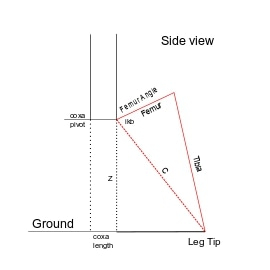
The purpose of Inverse Kinematics is to determine the position of a point in 3-D space. In the case of a hexapod, the point is the leg tip. If we show an overhead view of a single leg and project it on an XY graph with the coxa pivot point being the 0,0 point, we can represent our starting point. The user will input the desired X, Y and Z (height) values. Using those values we can project a line (L1) that forms a right triangle. Using the Pythagoras Theorem where the length of L1 is the square root of the sides squared and added together. The coxa angle is the angle derived from the tangent of Y/X. So coxa is the first angle determined.
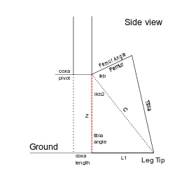
Next view is looking at hexapod leg that starts at the coxa pivot, extends to the femur pivot and then the tibia pivot and down to the ground. L1 from the first step is the total length from the coxa pivot point to the leg tip. Since we are looking for the femur and tibia angles this step starts to cutting the drawing up into various triangles. First remove the coxa length from L1 to get the distance between the leg tip and directly below the femur pivot point.
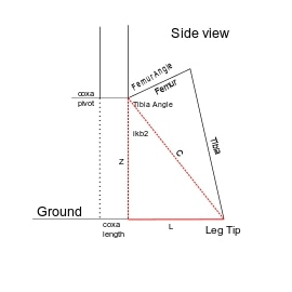
With the length of L along the ground, draw a line (C) from the tibia pivot to the leg tip to create another right triangle. Use Pythagoras Theorem again to find C. Now use sine or cosine to get angle ikb2.
Next step is using the triangle in red and the law of cosines to get the angle ikb since we have the lengths of all 3 sides.
Calculate the femur angle by adding ikb and ikb2 angles together. Now in my setup the femur angle is other side of the line that is the femur and the red/black line (just the way the leg was programmed) so convert this by 180 - (ikb + ikb2) to get the actual femur angle.
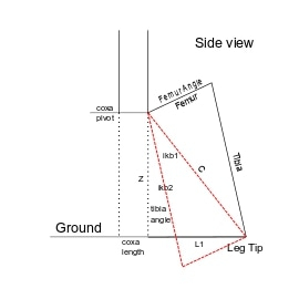
The last view is used to get the tibia angle. The tibia angle is the angle the leg tip goes out from a vertical line through the tibia joint. Due to the design of my hexapod this angle is also the angle of a parallelogram that is represented by the femur and tibia lengths. So we describe another triangle in red where we know the length of 3 sides. Using the law of cosines again we get angle ikb1. So the tibia angle is ikb2 - ikb1.
This is all calculated on the P2 using this routine:
pub legIK(x1, y1, z1): femurAngle1, tibiaAngle1, coxaAngle1 | L, L1, c, ikb, ikb1, ikb2, t1, t2, t3, t4
' output leg angle values for leg position inputs
  L1,t1 := cart_pol(x1, y1)
  coxaAngle1 := t1
  L := L1 - coxalength
  C,ikb2 := cart_pol(z1, L)
  ikb := law_of_cosine(femurlength, C, tibialength)
  femurAngle1 := 1800-(ikb+ikb2)                                                'convert angle to measure from CW direction vs CCW.
  ikb1 := law_of_cosine(tibialength, C, femurlength)
  tibiaAngle1 := ikb2-ikb1
'  debug("IK output: ", sdec(femurAngle1), sdec(tibiaAngle1), sdec(coxaAngle1))

pub cart_pol(x1, y1) : r, t
'' Convert coordinate x,y to polar (length, angle) - written by JonnyMac
  org
                        qvector   x1, y1                        ' cartesian to polar
                        getqx     r                             ' get radius (length)
                        getqy     t                             ' get theta (angle)
                        qdiv      t, ##1193046                  ' convert angle to 0.1 degree units
                        getqx     t
  end

pub law_of_cosine(a, b, c): angle| scale1, t1, t2, t3
' apply law of cosines to input length values where a, b, c are the lengths of the triangle sides
' return angle is angle between a and b sides
' acos based on Flexspin pasm conversion of spin based acos
  org
            mov     scale1, ##1000                                      'save scaling factor
            qmul    a, a                                                'square the a parameter
            getqx   t1                                                  'a squared result

            qmul    b, b                                                'square b param
            getqx   t2                                                  'b squared result

            qmul    c, c                                                'square c param
            getqx   t3                                                  'c squared result

            add     t1, t2                                              'add a2 + b2
            sub     t1, t3                                              'subtract c2, save in t1

            qmul    t1, scale1                                          'scale value to keep in desired interger value range
            getqx   t1                                                  'save scaled value to t1

            qmul    a, #2                                               'multiply a param by 2
            getqx   t2                                                  'save result in t2

            qmul    t2, b                                               'multiply t2 by b param
            getqx   t2                                                  'save result in t2

            abs     t1          wc
            qdiv    t1, t2                                              'divide t1 & t2
            getqx   t3                                                  'save result in t3 - integer value for acos
    if_be   neg     t3

    _acos1
            qmul    t3, t3                                              'square t3
            getqx   t1                                                  'save to t1
            qdiv    t1, scale1                                          'divide t1 by scale
            getqx   t2                                                  'save result in t2
            mov     t1, scale1                                          'save scale to t1
            sub     t1, t2                                              'subtract t2 from scale value
            qmul    t1, scale1                                          'multiply t1 by scale
            getqx   t1                                                  'save result to t1
            cmps    t1, #0      wcz                                     'compare t1 to 0
    if_be   mov     t2, #0                                              'if t1 = 0, then t2 = 0 - not sure of purpose???
            qsqrt   t1, #0                                              'take square root of t1
            getqx   t2                                                  'save result to t1
            qvector t3, t2                                              'get angle based on adjacent and opposite side of triangle
            getqy   angle                                               'get angle value
            qmul    angle, ##3600                                       'convert angle value to degrees
            getqy   angle                                               'return angle
  end
The P2 routines are fairly simple (I need to optimize the law_of_cosine but it works!) to follow.
This post has gotten long enough, next time I'll show how to go the other way, given the coxa, femur, and tibia angles, find the X,Y, and Z coordinates. This is a great way to check the IK math out. It is also needed during hexapod startup to find the starting position of each leg before any leg movement.
Today I want to show how to calculate the X,Y,Z positions with only knowing the initial motor angles.
In this case the hex robot has been just turned on. The individual leg controllers are querying the encoders and then converting those values to a motor angle. This data is then transmitted back to the P2 master.
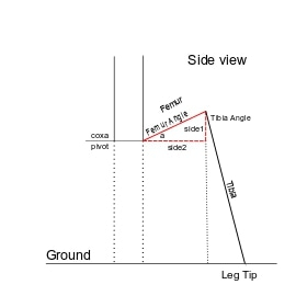
Looking as a side view of a simplified drawing of the leg, the goal is to get the total distance between the leg tip and the point directly below the coxa pivot point. Since we know the distance between the coxa pivot and the femur pivot, another line can be drawn to the ground from the femur pivot. My method was to draw another line vertically from the tibia pivot to ground forming a right triangle. This allows me to create a smaller right triangle using the femur length as the hypotenuse and a horizontal line over to the tibia line. Since the horizontal line is at 90 degrees to the vertical femur pivot, the angle 'a' is simply 90 - femur angle. There is one caveat, the drawing doesn't show the situation where the femur angle is greater than 90 degrees. In that case there is still a right triangle but it is flipped upside down and angle 'a' is femur angle - 90 degrees. Whether the triangle is upright or upside down becomes important later.
With angle 'a' and the femur length, the values for side1 and side2 can be calculated using the sine and cosine of angle 'a'.
We now have the coxa length and the side2 length, all that is needed now is the bigside2 length and the long side bigside1 from the tibia pivot to the ground. This is another right triangle where we know the tibia angle and tibia length, so it is calculated the same way as the other triangle using sine and cosine.
Next is getting the Z height of the femur pivot above the ground. if the femur angle is less than 90 degrees then bigside1 - side1 is = Z. If femur angle is > 90 degrees then Z = bigside1. Now we have all the information for the total length between the coxa pivot point and the leg tip.
L1 is the distance that was just calculated so now we go to the overhead view of the hexapod leg. Again we have a right triangle, the value of L1 and the coxa angle so X and Y come from using sine and cosine.
The resulting X,Y,Z values are used as the starting points for any leg movements.
pub getXYZ(a, b, c): x1, y1, z1 | angle1, side1, side1Angle, side2, side2Angle, bigside1, bigside1Angle, bigside2, bigside2Angle, L1
' calculate leg tip x,y,z position based on input angles
' a is femur, b is tibia, c is coxa
  'get femur angle into right range
  if a > 900
    angle1 := a - 900
  else
    angle1 := 900 - a
  'get sides of right triangle
  side2Angle, side1Angle := cosine(angle1)
  side1 := (side1Angle * femurLength)/1000
  'get horizontal part of right triangle
  side2 := (side2Angle * femurLength)/1000
  'get height to tibia pivot
  bigside1Angle, bigside2Angle := cosine(b)
  bigside1 := (bigside1Angle * tibiaLength)/1000
  if a < 900
    z1 := bigside1 - side1
  else
    z1 := bigside1 + side1
  'get last side of tibialength and bigside1 right triangle
  bigside2 := (bigside2Angle * tibiaLength)/1000
  'get L1 value
  L1 := side2 + bigside2 + coxaLength
  'get x, y values based on L1 and coxaAngle
  coxaAngle := coxaAngle *1000
  x1, y1 := cosine(c)
  x1 := (x1 * L1)/1000
  y1 := (y1 * L1)/1000
  debug("showXYZ output: ", sdec(x1), sdec(Y1), sdec(z1))
Here is the P2 code used to get the coordinates. Since I am using integer math, 900 corresponds to 90.0 degrees.
A couple of posts ago I was working on code that verified that the IK angles were valid and within the mechanical reach of the legs. Each motor has a minimum and maximum angle value it is capable of reaching. Additionally the design of the femur and tibia allow them to physically interfere with each other so that is a further limitation. Through experimentation I found that if the femur angle minus (-) the tibia angle is less than 30 degrees, there is interference. Taking that information I came up with this piece of code to check for illegal positions
con
  'leg constants
  femurMinAngle = 320
  femurMaxAngle = 1500

  tibiaMinAngle = 0
  tibiaMaxAngle = 520

  coxaMinAngle = 290
  coxaMaxAngle = 1510

pub checkLegContraints(f, t, c): result | a
'valid input angle values are within mechanical limits
  'returns %0000_0000 if constraints are met, binary value >0 identify error condition
  debug(" ")
  debug("----- CheckLegConstraints -----")
  result := %0000_0000
  'check if angles within min and max values
  if (f < femurMinAngle) OR (f > femurMaxAngle)
    result := %0000_0001
  if (t < tibiaMinAngle) OR (t > tibiaMaxAngle)
    result := %0000_0010 + result
  if (c < coxaMinAngle) OR (c > coxaMaxAngle)
    result := %0000_0100 + result
  'check for femur/tibia interference
  if ((1800 - f) - t) < 300
    result := %0000_1000 + result
  if result == %0000_0000
    debug("No leg contraints")
  else
    debug("Error, leg contraints")
This code works pretty good for what it does. The result value is read using a mask to determine which error is the problem. Now I need to figure out what to do about an error other than just stopping all motors on all legs. I also want to display the error somehow.
This brought up another related item when I was commanding the leg to move in a straight line the first time. After the movement it is supposed to return to the starting point (X,Y,Z coordinate). In this case the tibia did not move despite having a valid movement code sent. It did show a RED error on the LEDs but I have no way of knowing what caused that red light to go on other than it is the tibia. Going to think this one through for a bit and see if there is a way to transmit that info easily without having to re-write a lot of the feedback code on the P1 and P2.
Another thing I found during my testing of leg straight line movement is that the coxa rotation is very restrictive (29.0 to 151.0 degrees) which was caught by the above code. Another item brought out is that the tibia angle minimum value is 0 degrees. Ideally it should be able to go negative enough that when the femur angle is at 90 degrees, the leg tip can move to directly under the femur pivot point. Since 0 is the minimum this makes it more difficult for some legs to start stepping. Unfortunately both of these issues will require machining some modifications into the legs to allow the greater movement. This was a worry that I had quite a while back but I thought I could program around it when I got to this point. Now that I am here, programming so many exceptions will complicate the code quite a bit. I think I can live without the tibia change but the coxa range really needs to be expanded from 0 - 180 degrees.
I found a coding error in the leg controller that didn’t allow the tibia to move if I entered 0º and I was getting a RED error lights on the tibia and femur with no clue what was causing it. That was a fun(?!) bug to find as it manifests when running the P2 master but not when hooked up directly to the leg controller. I wrote the code discussed next to help narrow down where the error message was coming from.
I found a fairly simple way to transmit error codes to the P2 from the leg controllers. The P1 controllers serially send position data to the P2 every 6 ms. Included in that data is movement data that is used to run the RGB lights, basically a decimal value between 0 and 7 which correspond to the direction the leg is moving or #7 which was the error flag. So instead of just sending #7 when any error happened, I set up a series of specific decimal error values ranging from 10 to 16, so each possible error the leg controller tests for has a unique value and is sent instead of the previous single error flag.
On the P2 side the code looks at the incoming data, if the value is less than 10, the data is directly converted to the RGB color scheme for that action. If the data >=10 then the data value is saved in an error code variable (one variable for each motor and leg for 18 total variables) and the RGB lights get an instruction to put up the RED light. Now I can use the DEBUG print to view the specific origin for each possible error code generated by the leg controller (and any error’s picked up by the P2). It will be trivial to add additional error codes as needed.
Eventually I want to display these errors on the robot itself when it isn’t connected to an external computer, this might be a place to use the Nextion touchscreen display I got for one of JonnyMac’s P2 video lessons last year. I need to watch that video again to remember all its capabilities and how to connect it to the P2. This isn’t urgent so it will wait for later.
Did some measurements and I know a way to increase the coxa rotational range. I want to do this to make the walking gait easier to program.
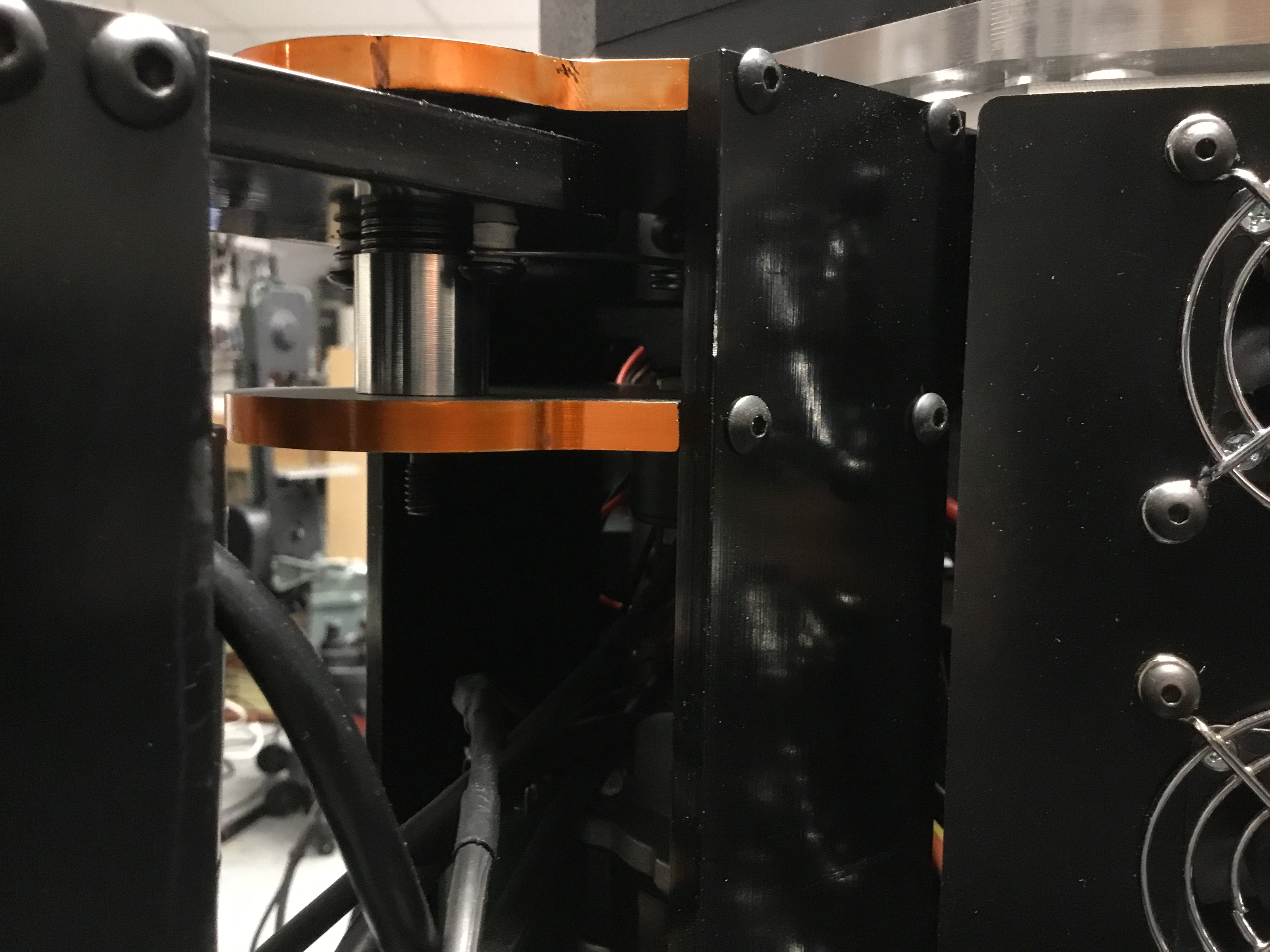
In the photo the side support is the 2” wide rectangular part that aligns the leg fixed pivot points on the robot body. The slots will be where the rotating part of the leg currently touches the side support when the pivoting piece is at maximum rotation in both directions. The pivot point is 0.75” back from the edge of the side support so cutting a 1.0” deep slot is wide enough for the moving part to move into will give the extra desired rotation. This slot will be on both sides and at the bottom for the lower pivot arm.
Spent the day machining the side supports for the robot, 6 legs, 12 side supports, 24 total cuts. It was fairly easy to program the CNC mill for the cuts, was able to to do everything right from the mill computer without having to modify the CAD drawings.
This is a closeup of the upper slot machined on both sides of the leg pivot point.
The next photo shows both slots on a side support.
This will allow the legs to move in 180º arcs vs 120º which will make programming walking easier. Now I have to calibrate the coxa on each leg for the encoder readings at the 0º and 180º positions. I need to pretty up the raw aluminum the milling exposed. Due to the small size of the exposed metal, most likely will use black paint instead of trying to anodize each piece again.
Started to do the calibration for leg #1. I realized that the magnetic encoder is 4096 counts for 360º of motion or 2048 counts for 0 to 180º. Since I know the 90º encoder value, I can just add or subtract 1024 to get pretty close to the 0º and 180º marks. Entered the expected data, put the leg controller in manual mode and told it to go to 0º, it didn’t move… Checking the code I found some error checking I added at some point that if the input value to the coxa was 0, then ignore the command as invalid. Obviously this is no longer true (plus I added other methods to check for valid input values) so that was removed. Now the leg moved but stopped around the 30º mark. I heard a distinct sound of metal striking metal so after a while of looking I realized the tibia motor mount was hitting the side supports (you can see the motor mount in the 2nd photo in the previous entry).
So I removed Leg #1 from the body and moved to the workbench. I removed the coxa motor assembly so I could freely move the leg on the coxa pivot. So I saw some issues that have to be resolved.
1 - The tibia motor mount limits coxa travel, This may require cutting the motor mount back some but the 2 bolts that hold the mount in place may also be in the way of full rotation. Another option is cutting away more of the side support in addition to modifying the motor mount.
2 - All the wires for sensors and motors come in on one side and when the coxa is a 90º, the wires are pinched pretty severely (not a problem at the other extreme of travel as no wires come in from that direction). A possible solution to this pinching is to machine an opening into the side support on the wiring side to allow extra room for the wires.
3 - The magnetic encoder setup for the coxa has a slight interference at the 2 extremes of travel which will require a slight modification to a coupler (make it about an 1.8” narrower).
This has turned into a much bigger job than I anticipated, should have done all this mechanical testing on the bench first before making the slots (although the slots will work as expected, I should have figured out the total scope of the ‘enhancement’ earlier! Going to take some time to figure this out and make sure I’m not introducing any other issues if I make these changes.
Leg 1 has been modified and is reinstalled and ready to test the changes. In the photo you can see most of the changes (just look for the raw aluminum). The slot on the top allows full 180º rotation. The bottom slot had to be cut out because of the coxa motor mount below. I didn’t modify the motor mount since that would have interfered with the mounting bolts on it. The bottom leg support was also cut more to allow full rotation. In the middle of the side support is a 1/2” x 2” cutout to allow the wires access to the robot body without getting pinched at 0º and 180º. I have to zip tie the wire bundles again so that they use the slot. I tried to re-route the wires but as I cut the wires to length for this position, any other spot meant I had to put in new wires or lengthen the existing wires. I also had to drill and tap new mounting holes on the side support piece.
As long as I had the leg in pieces I decided to go ahead and modify the wire routing of the leg touch sensor. Originally it passes up through the lower leg tube which looks great but because of the way the tube is held in place, the wire gets twisted and the wire insulation has gotten damaged. I drilled a 0.4” hole in the back side of the tube which is where the wire comes out now (instead of the other hole just a bit further up on the photo). This keeps the wire from being twisted when the leg down sensor is being screwed into the lower leg tube.
Start testing the changes after dinner and make sure everything works before I start changing the other 5 legs!
@JRoark said:
Looking at this whole thing… i’m just like WOW! Mad skills!
Thanks!
Finished up modifications to 3 legs, hopefully get the other 3 done tomorrow. I did test the modifications on leg #1 and it worked as expected.
The drive shaft support plates; from the pic, at least the bottom one appears to not be recessed (pocketed) in the side plate and therefore reliant on screw retainers for alignment (?)
@Mickster said:
The drive shaft support plates; from the pic, at least the bottom one appears to not be recessed (pocketed) in the side plate and therefore reliant on screw retainers for alignment (?)
Craig
Correct, the side supports are not pocketed and rely on the screws for alignment. The hole tolerances are pretty tight so to keep the parts perpendicular to each other. Further more the bottom and top plates are bolted into the robot body which also helps keep the frame rigid. The movable part of the leg is machined using pockets in the side supports as the screws are only 0.75 inch apart so pocketing improves the rigidity of the part.
@Mickster said:
I just get a "it's gonna twist" feeling. Easily remedied by banging a few dowels in there. Retainers are only intended to retain.
Craig
The leg is a very solid structure, it weighs in at around 26 lbs! The only flexing I am seeing is the lower leg extension where the leg goes to the ground. That part is a 1” round aluminum tube that is 12” long. So there is some flexing at the leg tip but that helps take up some of the motor movements since each motor moves its part of the leg at different speeds. I haven’t seen any indication that parts are going out of alignment in any of my testing, both on and off the test stand. There is also a lot of bracing that isn’t fully evident in the photos that keeps the parts that need to be rigid in alignment.


Comments
Happy to see continued progress. I think that auto correct is biting you in the a.. It changed LegDown to ledDown.
Jim
Today was spent performing a series of tests to make sure the new serial setup transmits correctly to the legs from the P2 master.
First test was the simplest, just send a movement command to a single leg. After a couple of false starts I got that running with no issues (Yay, first leg movement using the new serial setup!).
Next step expanded that test by sending a movement command to all legs at the same time. The leg controllers have their P1 pins wired together so data the P2 transmits 6 individual data packets out pin #5 ($,1,900,0,900,1,13 $,2, 1,900,0,900,1,13 and so on). Each P1 listens for the start char “$” and then if the delimiter (“,”) is followed by its leg number (1 through 6), it then copies the string up to the 13 (return char) and then acts on the string. The legs ignore any commands coming for the other legs.
When I sent a single command down the wire, the correct leg responds, proving the other legs knew to ignore the command.
Sending the command out to all 6 legs at the same time, I saw a problem. Initially only legs 1 and 4 responded. Debugging indicated that although correct outputs were generated by the P2 master, only the leg 1 and 4 were actually transmitted to the legs, leg 2, 3, 5, 6 commands were not transmitted.
I reviewed the serial demo which used a txflush() after transmitting. After adding this method I got 4 to 5 legs responding each time, but the one(s) not responding were different legs each time. Sending the same command a 2nd time resulted in the leg(s) that didn’t initially move would move to the right location. I added a 100ms wait between each leg transmitt which got 5 out of 6 responding but again, still had different legs not responding each time. Next step was changing the baud rate on the P2->P2 line from 115_200 to 57_600 on the transmitt line to see if that helps. Not so much as now nothing is responding which is where I left it after much head scratching. My next check is to put a logic analyzer on the output line from the P2 and see if I’m getting any garbage out of the P2. As I’m sitting here typing this another idea comes to mind that instead of sending 6 separate strings from the P2, maybe combine them into a single string and see how that works.
Bob,
I like the idea of using a single string to address all six legs. It seems to me that I have seen P1 code that would allow parsing that string by segment numbers like a basic midstr command. That might solve the problem as each leg gets the section of the string it needs.
Wishing you continued successes.
Jimj
Thinking out loud here: What about turning the address portion into a bitmask. Each addressed device looks at its corresponding bit in the address byte to decide if it needs to even pay attention to the message. Then, within the string, there is a “slot” for each device to “look at” for the command/value info being sent to that device. This makes the entire command string a fixed number of fields and makes the comm line more like a bus. This could make it capable of nearly any topology (series, parallel, star, tree, ad hoc). Replies from each leg would probably need to be polled, but depending on your needs this may not be a big issue.
Thanks for the ideas everyone!
Later last night I was in my favorite chair thinking about the problem, I had another thought about what to try out. I’ve been trying to run this ‘network’ the same way I did when the master computer was a P1 and I was having issues with the processor speed, number of available cogs, available output pins, available memory, and limitations of some of the P1 objects I was using. Now that the P2 is in the mix most of those issues aren’t an issue anymore.
The current configuration has 6 ports, P1->P2, set up to receive data only (no transmit pin configured). A 7th port is used to transmit P2->P1 data. Since I have an abundance of P2 ports, why not just use the 6 ports ports to send and receive? The code on the P1 side can stay the same (although it wouldn’t need a leg number value to parse which helps with speed). The transmit code on the P2 side is easily modified to send out over separate ports instead. With this setup, any command coming into a P1 controller is data to act on. I don’t think this will make a difference on the P2 side of things as far as speed is concerned.
Looks like I have some port re-wiring, coding, and testing to do today!
Bob
Yes, 32 extra pins can be a big bene!
Jim
Rewired the P2 to P1 controller serial setup. Pins 4 through 15 on the P2 are wired to each of the P1 RoboPi boards on pins 1 (rx) and 2 (tx).
No changes were made to the P1 code as I am still using the original serial string setup for now. The P2 code required a few changes, 6 ports that were only receiving P1 data now have a tx pin assigned.
Testing the ports consisted of first reading the data from the individual P1's which was successful. Next step was transmitting a movement command to Leg 1. In this case Leg 1 failed to respond. To make sure data was being sent correctly a logic analyzer was connected to P2 to leg 1 transmit pin. The analyzer showed that data in the correct format was being sent to the leg controller. (see the attached file).
Now I have to figure out why the P1's aren't responding to the movement command. I have verified the baud rates are the same (57600) on the P1 and P2. Wiring was checked several times and it all lines up as expected. The movement command format from the P2 is showing up correctly on the analyzer. Most likely it is something simple that I a overlooking... Back to work now
Bob
EDIT: Not finding the problem so far. The movement command string is good but the leg controllers are not recognizing it. Although I didn't change anything with the leg controller code, I will get back in there and test the controllers and see what is going around in there. There is on thing that is puzzling me, the commands out of the P2 have a '\r' showing on the analyzer at the end of the string where I am sending a value of '13' for CR. This could just be the way this analyzer's ascii displays the CR value. The P1 outputs also show the same \r instead of CR but the P2 is handling that OK. I don't think this is the problem but it doesn't make sense either. Time for a break away from the computer to mull this over.
I once spent the better part of a day chasing something like this. Turned out the data was perfect… except the serial line idle state on one side was inverted compared to the other. (-facepalm!-)
Gathering more information for troubleshooting the serial communications between the P2 to P1 leg controllers. I re-ran all my tests from yesterday with the same results. The logic analyzer is still showing the P2->P1 commands as being transmitted correctly but none of the legs are responding to the request.
Next test was to set the P2 to repeat the movement request to the Leg 1 controller on a 1 second cycle. I used the analyzer to verify the request was being sent to the Leg 1 controller on a loop. Next step was moving the prop plug from the P2 over to the leg 1 controller. I put the code in manual mode and entered a movement command manually via the PST, this worked as expected and the leg moved to the new position. I put the code back in automatic mode and resent the code to the controller. This time the leg moved to the position being sent from the master. I was able to repeat this by manually moving the leg to various positions and as soon as I recompiled the controller in automatic mode (where it listens for input from the P2), it would move to the P2's requested position.
This proves the data is being sent and received by the leg controllers but they are not acting on the data. Next step is crunching through the P1 code to figure this out (too bad DEBUG doesn't work on P1 code - I still have a lot of embedded debugging print statements to the PST that are active when in manual mode). Slowly narrowing this problem down!
Edit: On the P2 side I wrote a routine to change the femur position by 2 degrees every second between 60 and 120 degrees. Same results as above except I kept the leg 1 in auto mode and every time I re-compiled the P1 code, the leg would move to another position but only made the one move. It appears the P1 is seeing only one input command at a time and ignoring all the rest in this situation. Continuing to try and narrow down the bottleneck in the P1 code.
During troubleshooting I found that putting a 5ms delay right after the code that reads the incoming data from the P2, then the leg responds as expected to each incoming P2 move command. If the delay is less than 5 ms, it stops working again. Based on this observation, it appears that the code reading the incoming P2 data and stuffing the data into a buffer needs the extra time to complete the task as the next task is extracting the comma delimited angle data from the buffer. Either way, it is working again using the new serial object!
With the leg moving again with the P2 input commands I was able to see some things from the logic analyzer that lead me to make some more minor P1 code changes. Now that the P2 is directly wired to each P1, sending the leg # data isn't really necessary so I commented out the code that looks specifically for the leg. I will use the same data format for the string coming into the P1 (numbers 1...6 were leg numbers, 7, requests leg calibration, 8 is setting motor speed, and 9 is an emergency stop) and made a few other minor P1 changes as long as I was going to have to upload the program to the EEPROM's on all the leg controllers.
I want to finish up the P1 code changes and test them out individually on each leg before I get back to the P2 coding
Still working on the P1 coding, the logic analyzer has become very useful at this point. I set the P2 in a loop to output to Leg 1 a changing femur position between 60 and 120 degrees and then back down to 60º in 2 degree increments with 500 ms between each command. The P1 controller is sending data back to the P2 every 12ms the leg position. Per the analyzer, after the leg controllers receive a movement command, it takes about 20 ms for the leg to physically start to respond (based on when the P1 feedback shows movement). Typically a 2º femur movement takes about 100 ms to complete the movement and show a steady position. This also captures any leg movement errors by flashing the RGB lights so a red flash indicates something didn’t go the way it should have. Having these additional tools has helped me to identify some problems that aren’t apparent when manually entering movement data
So I’m going to work my way down this list and fix the issues as they come up. Sure that a few other items will show up in the meantime. I do need to figure out a faster way to calibrate the PID loop, right now there are 3 main variables that impact the PID and calibration means increasing one value at a time until the leg tends to oscillate, back it back down and then do the same for the next variable. This takes a lot of time as there are subtle effects between the variables also so I go back and forth several times.
Bob
I started working on problem #4 first (I know, out of order but it captured my interest the most). Reviewing the coxa movement initiation code and PID I couldn’t figure out what would cause the PID loop to be entered without a movement command. I started a debug display of the input string from the P2. Here I discovered that occasionally the P1 wasn’t capturing all the P2 serial data so instead of “$,900,0,900,1”, it might come out as “$,900,0,9”. This prompted a review of the code that receives the serial and appends the data into the string. I was using rxcheck() for receiving data so I changed that to rx() instead. With this code change the reliability of the input string was improved greatly and the incidence of missing data was almost eliminated. This solved Problem #4, #3, and part of #2.
Problem #1 (and #2) were directly related to tuning of the PID loops for both motors. I tuned these using information I read about tuning PID loops in general. Increase the Kp value until the output oscillates and then back it down until it doesn’t. Repeat the same for the ki variable. I did this again but came up with the same kp/ki values as before. Now this is where the information on the logic analyzer came in very handy. Data from the P2 was coming in every 500ms and the P1 was sending actual position information along with motor direction data back to the P2 every 12 ms. Starting out with a P2 command I could see that the motor started to respond after around 15ms. I counted the number of P1 feedback pulses that showed power to the motor. When the P1 feedback showed the motor to be OFF, I then watched the motor angle change until it stopped changing. This time is how long it takes for the motor to physically stop. For moving 2º, the femur took about 100ms more to actually stop. In many instances although the motor was stopped within 0.5º of the requested location, inertia moved the femur another 1º-1.5º more.
I used this information to manipulate the Kp, Ki, and deadband variables. Increasing the deadband value to 1º tells the motor to stop sooner and then I use the inertia to glide closer to the actual requested value. By using the analyzer and watching the P1 feedback after a P2 command, I was able to find better values which ended up improving the response.
I was able to repeat the same system to tune the tibia motor for the same improvement. The coxa was a bit different as it has a custom gearbox including the one built in to the motor so when the motor stopped, there was no additional inertia movement no matter what variable changes I made. In the end I kept the values all the same.
Next step is verifying the code changes work on each leg and then loading the P1 EEPROM’s with the new program.
I think the next thing on the agenda is to see how well a single leg tip does when the P2 tells it to move in a straight line. This will test out the new Inverse Kinematics equations and code. I described a while ago that I found a mistake in my geometry which might explain some of the inconsistencies I saw the last time I was at this point. Since then I’ve added the magnetic encoders, switched to the P2, using integer math for all IK calculations, and fixed the geometry issues.
Spent more time calibrating the legs after I wrote the last entry. As noted earlier there was a lot of leg oscillation in the femur and tibia movements when the P2 was sending commands to move the leg in 2 degree increments for these 2 motors. I found that if I put some tension on the leg by lifting it up while it was moving, the oscillations mostly went away. Tension in the upward direction is what the leg would normally be experiencing if the leg was supporting the weight of the robot. I tuned the PID to mostly remove the oscillation with tension on the leg. In cases where the leg has to be picked up I am looking at a mechanical solution such as putting a torsion spring on the femur and tibia pivot points to provide the tension. I wasn't able to locate a suitably sized torsion spring so I will be ordering spring wire and winding my own springs.
Of course all this experimentation reveals other problems/issues to solve which has been taking up the rest of the time. I fixed one issue with a code fix which broke another part of the code (femur wouldn't respond if I told it to got to 120 degrees, it worked for all other angles, just not this one (harder to find this one as it was a change I put in quite a while ago).
To start testing moving the leg in a straight line, I wanted to make sure the Inverse Kinematics code was working right first. A quick test is to startup leg controllers, retrieve motor angle data. The P2 converts this angle data into an x/y coordinate. Now I feed that same coordinate back into the P2 IK routine and theoretically I should get the same angle data. Well, that didn't happen. So here is where the DEBUG statement in Spin2 comes in real handy to watch the calculations (including the in-line PASM code) and compare each step to the calculations I did by hand using a calculator. Tonight I finally got the hand calculated values for the angles to match the coded values. I need to run a few more leg positions through the calculator and make sure I didn't miss anything. I also have to put in some error coding to catch situations where input IK values result in a bad output.
Unfortunately there isn't much to video or take a picture of other than screen shots. I'll post the IK code once I verify its working right for more leg positions.
Bob
Hi Bob,
I confess to have only just looked at this (huge) thread for the first time. Mainly because a "robot", here, usually means a rickety open-loop articulated arm or something on wheels that, for me, is more accurately described as an AGV.
This means that I've only glanced at the last few posts but I see that you are working on something really interesting.
Based on what I've read, this would be my approach:
PID:
Forget the KI, you will never achieve stability during motion. In terms of a car suspension unit, KP is the spring and KD is the shock-absorber. KI is used to reduce/eliminate final position error and is best applied when very close to steady state. If you must use KI, have an IL (integrator limit) to prevent wind-up. Unless you want the Hexapod doing the Fandango all over the floor
Run the PID @ 1KHz and within that loop, at somewhere ranging from 2 to 100 samples (whatever works best), update a discretized position command.
IOW, every 10 samples = 100Hz and so, for example, if the target position (aka: waypoint) is 20 degrees and the desired velocity is 20 degrees/Sec, increment the command position 0.2 degrees/ 10 samples. Do the same for all axes and they become self-interpolating.
Edit: Forgot to mention that this can be further broken down to the PID loop update rate.
During motion, the master is buffering the next waypoint in the P1. All the P1 needs to return to the master is a status byte to confirm that the command was received without a checksum error.
Binary serial communication (only one serial bus):
Header byte (I use 0xAA)
Address byte (0x01 to 0x06 for individual addressing, 0xFF for broadcasting)
Command/control byte (dictates what needs to happen (upper nibble) and the number of following data bytes (lower nibble))
Data bytes (whatever is required)
Checksum
From what I have read, I feel that your communications are way busier than they need to be.
Craig
Thanks Mickster for the suggestions. I did reduce the frequency of the PID loop to see if that helps. The code was already set up to allow new motion updates even if the previous motion had not completed. This should help smooth out the actual motor movement. I will have to experiment to determine the best PID frequency for motion. I actually use a PI loop, Derivative was not useful when I set that up. There a limiter on the KI value and it gets reset every time the leg reaches its destination to prevent windup (I used to work and calibrate commercial PID products in a previous job).
I like your idea on the communications side of things but I didn’t want to re-write the P1 code also. However I did reduce the amount of passed data and came up with a simple method of validating data was being transmitted. Incomplete data transmissions are ignored on both the P1 and P2 sides.
Over the last 2 weeks I’ve spent the majority of time (2-4 hours each day!) resolving problems as they crop up. It seems that now I have the P2 in place I am able to identify coding problems more easily than by just testing individual leg operation using the P1 leg controllers. Finding one problem and fixing it tends to lead to identifying another problem that was hidden and the cycle continues.
In order to test moving a single leg in a straight line, I need to know the initial position of the leg tip based on a x, y, z coordinate. I can manually enter a coordinate position and then the motors will move the leg to that position. To test this process, I wrote a routine that returns the calculated x, y, z position after the leg has moved (It uses a different process than what was used to get motor angle data so this is another validation that the math is correct). This shows how close the leg ends up to the original input position. Initially the positions were wildly different, troubleshooting (I love the Debug ability in Spin!) identified the leg Inverse Kinematics wasn’t calculating the right angles for the motors. This turned out to be a mistake in the geometry that was subtle but introduced cumulative errors. Lots of time running calculations in code and then manually running the same calculations on paper until they matched.
Next step was identifying minimum and maximum coordinates that resulted in femur, tibia, and coxa angles that were not mechanically possible. Each motor has a limited range of angles that it can physically move to. Additionally, the Femur and Tibia can further mechanically interfere with each other so that was added to a validation routine. At this point I am testing this new routine which outputs an error code based on the actual issue (still have to figure out how to display that if the robot isn’t hooked up to a computer to display debug information. I did get a Lascar programmable display that could be mounted on the robot and send text to the panel to show information like that).
My problem list is down back down to a single issue that I will start work on tomorrow.
I used the LM628/629 datasheet as a reference (pages 11 & 12)
Cheers!
Craig
Here is an update on the Inverse Kinematics math used to develop the leg movement software. I made up some drawings to help demonstrate the process used. I'm sure there are other methods to get the same results (let me know if anyone finds any mistakes!) but this method seems to be working so far.
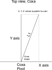
The purpose of Inverse Kinematics is to determine the position of a point in 3-D space. In the case of a hexapod, the point is the leg tip. If we show an overhead view of a single leg and project it on an XY graph with the coxa pivot point being the 0,0 point, we can represent our starting point. The user will input the desired X, Y and Z (height) values. Using those values we can project a line (L1) that forms a right triangle. Using the Pythagoras Theorem where the length of L1 is the square root of the sides squared and added together. The coxa angle is the angle derived from the tangent of Y/X. So coxa is the first angle determined.
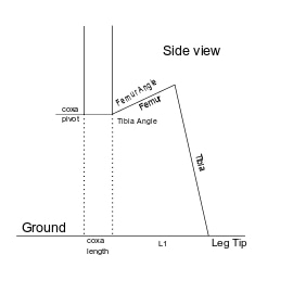
Next view is looking at hexapod leg that starts at the coxa pivot, extends to the femur pivot and then the tibia pivot and down to the ground. L1 from the first step is the total length from the coxa pivot point to the leg tip. Since we are looking for the femur and tibia angles this step starts to cutting the drawing up into various triangles. First remove the coxa length from L1 to get the distance between the leg tip and directly below the femur pivot point.
With the length of L along the ground, draw a line (C) from the tibia pivot to the leg tip to create another right triangle. Use Pythagoras Theorem again to find C. Now use sine or cosine to get angle ikb2.
Next step is using the triangle in red and the law of cosines to get the angle ikb since we have the lengths of all 3 sides.
Calculate the femur angle by adding ikb and ikb2 angles together. Now in my setup the femur angle is other side of the line that is the femur and the red/black line (just the way the leg was programmed) so convert this by 180 - (ikb + ikb2) to get the actual femur angle.
The last view is used to get the tibia angle. The tibia angle is the angle the leg tip goes out from a vertical line through the tibia joint. Due to the design of my hexapod this angle is also the angle of a parallelogram that is represented by the femur and tibia lengths. So we describe another triangle in red where we know the length of 3 sides. Using the law of cosines again we get angle ikb1. So the tibia angle is ikb2 - ikb1.
This is all calculated on the P2 using this routine:
pub legIK(x1, y1, z1): femurAngle1, tibiaAngle1, coxaAngle1 | L, L1, c, ikb, ikb1, ikb2, t1, t2, t3, t4 ' output leg angle values for leg position inputs L1,t1 := cart_pol(x1, y1) coxaAngle1 := t1 L := L1 - coxalength C,ikb2 := cart_pol(z1, L) ikb := law_of_cosine(femurlength, C, tibialength) femurAngle1 := 1800-(ikb+ikb2) 'convert angle to measure from CW direction vs CCW. ikb1 := law_of_cosine(tibialength, C, femurlength) tibiaAngle1 := ikb2-ikb1 ' debug("IK output: ", sdec(femurAngle1), sdec(tibiaAngle1), sdec(coxaAngle1)) pub cart_pol(x1, y1) : r, t '' Convert coordinate x,y to polar (length, angle) - written by JonnyMac org qvector x1, y1 ' cartesian to polar getqx r ' get radius (length) getqy t ' get theta (angle) qdiv t, ##1193046 ' convert angle to 0.1 degree units getqx t end pub law_of_cosine(a, b, c): angle| scale1, t1, t2, t3 ' apply law of cosines to input length values where a, b, c are the lengths of the triangle sides ' return angle is angle between a and b sides ' acos based on Flexspin pasm conversion of spin based acos org mov scale1, ##1000 'save scaling factor qmul a, a 'square the a parameter getqx t1 'a squared result qmul b, b 'square b param getqx t2 'b squared result qmul c, c 'square c param getqx t3 'c squared result add t1, t2 'add a2 + b2 sub t1, t3 'subtract c2, save in t1 qmul t1, scale1 'scale value to keep in desired interger value range getqx t1 'save scaled value to t1 qmul a, #2 'multiply a param by 2 getqx t2 'save result in t2 qmul t2, b 'multiply t2 by b param getqx t2 'save result in t2 abs t1 wc qdiv t1, t2 'divide t1 & t2 getqx t3 'save result in t3 - integer value for acos if_be neg t3 _acos1 qmul t3, t3 'square t3 getqx t1 'save to t1 qdiv t1, scale1 'divide t1 by scale getqx t2 'save result in t2 mov t1, scale1 'save scale to t1 sub t1, t2 'subtract t2 from scale value qmul t1, scale1 'multiply t1 by scale getqx t1 'save result to t1 cmps t1, #0 wcz 'compare t1 to 0 if_be mov t2, #0 'if t1 = 0, then t2 = 0 - not sure of purpose??? qsqrt t1, #0 'take square root of t1 getqx t2 'save result to t1 qvector t3, t2 'get angle based on adjacent and opposite side of triangle getqy angle 'get angle value qmul angle, ##3600 'convert angle value to degrees getqy angle 'return angle endThe P2 routines are fairly simple (I need to optimize the law_of_cosine but it works!) to follow.
This post has gotten long enough, next time I'll show how to go the other way, given the coxa, femur, and tibia angles, find the X,Y, and Z coordinates. This is a great way to check the IK math out. It is also needed during hexapod startup to find the starting position of each leg before any leg movement.
Bob Sweeney
Today I want to show how to calculate the X,Y,Z positions with only knowing the initial motor angles.
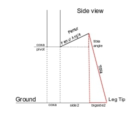


In this case the hex robot has been just turned on. The individual leg controllers are querying the encoders and then converting those values to a motor angle. This data is then transmitted back to the P2 master.
Looking as a side view of a simplified drawing of the leg, the goal is to get the total distance between the leg tip and the point directly below the coxa pivot point. Since we know the distance between the coxa pivot and the femur pivot, another line can be drawn to the ground from the femur pivot. My method was to draw another line vertically from the tibia pivot to ground forming a right triangle. This allows me to create a smaller right triangle using the femur length as the hypotenuse and a horizontal line over to the tibia line. Since the horizontal line is at 90 degrees to the vertical femur pivot, the angle 'a' is simply 90 - femur angle. There is one caveat, the drawing doesn't show the situation where the femur angle is greater than 90 degrees. In that case there is still a right triangle but it is flipped upside down and angle 'a' is femur angle - 90 degrees. Whether the triangle is upright or upside down becomes important later.
With angle 'a' and the femur length, the values for side1 and side2 can be calculated using the sine and cosine of angle 'a'.
We now have the coxa length and the side2 length, all that is needed now is the bigside2 length and the long side bigside1 from the tibia pivot to the ground. This is another right triangle where we know the tibia angle and tibia length, so it is calculated the same way as the other triangle using sine and cosine.
Next is getting the Z height of the femur pivot above the ground. if the femur angle is less than 90 degrees then bigside1 - side1 is = Z. If femur angle is > 90 degrees then Z = bigside1. Now we have all the information for the total length between the coxa pivot point and the leg tip.
L1 is the distance that was just calculated so now we go to the overhead view of the hexapod leg. Again we have a right triangle, the value of L1 and the coxa angle so X and Y come from using sine and cosine.
The resulting X,Y,Z values are used as the starting points for any leg movements.
pub getXYZ(a, b, c): x1, y1, z1 | angle1, side1, side1Angle, side2, side2Angle, bigside1, bigside1Angle, bigside2, bigside2Angle, L1 ' calculate leg tip x,y,z position based on input angles ' a is femur, b is tibia, c is coxa 'get femur angle into right range if a > 900 angle1 := a - 900 else angle1 := 900 - a 'get sides of right triangle side2Angle, side1Angle := cosine(angle1) side1 := (side1Angle * femurLength)/1000 'get horizontal part of right triangle side2 := (side2Angle * femurLength)/1000 'get height to tibia pivot bigside1Angle, bigside2Angle := cosine(b) bigside1 := (bigside1Angle * tibiaLength)/1000 if a < 900 z1 := bigside1 - side1 else z1 := bigside1 + side1 'get last side of tibialength and bigside1 right triangle bigside2 := (bigside2Angle * tibiaLength)/1000 'get L1 value L1 := side2 + bigside2 + coxaLength 'get x, y values based on L1 and coxaAngle coxaAngle := coxaAngle *1000 x1, y1 := cosine(c) x1 := (x1 * L1)/1000 y1 := (y1 * L1)/1000 debug("showXYZ output: ", sdec(x1), sdec(Y1), sdec(z1))Here is the P2 code used to get the coordinates. Since I am using integer math, 900 corresponds to 90.0 degrees.
A couple of posts ago I was working on code that verified that the IK angles were valid and within the mechanical reach of the legs. Each motor has a minimum and maximum angle value it is capable of reaching. Additionally the design of the femur and tibia allow them to physically interfere with each other so that is a further limitation. Through experimentation I found that if the femur angle minus (-) the tibia angle is less than 30 degrees, there is interference. Taking that information I came up with this piece of code to check for illegal positions
con 'leg constants femurMinAngle = 320 femurMaxAngle = 1500 tibiaMinAngle = 0 tibiaMaxAngle = 520 coxaMinAngle = 290 coxaMaxAngle = 1510 pub checkLegContraints(f, t, c): result | a 'valid input angle values are within mechanical limits 'returns %0000_0000 if constraints are met, binary value >0 identify error condition debug(" ") debug("----- CheckLegConstraints -----") result := %0000_0000 'check if angles within min and max values if (f < femurMinAngle) OR (f > femurMaxAngle) result := %0000_0001 if (t < tibiaMinAngle) OR (t > tibiaMaxAngle) result := %0000_0010 + result if (c < coxaMinAngle) OR (c > coxaMaxAngle) result := %0000_0100 + result 'check for femur/tibia interference if ((1800 - f) - t) < 300 result := %0000_1000 + result if result == %0000_0000 debug("No leg contraints") else debug("Error, leg contraints")This code works pretty good for what it does. The result value is read using a mask to determine which error is the problem. Now I need to figure out what to do about an error other than just stopping all motors on all legs. I also want to display the error somehow.
This brought up another related item when I was commanding the leg to move in a straight line the first time. After the movement it is supposed to return to the starting point (X,Y,Z coordinate). In this case the tibia did not move despite having a valid movement code sent. It did show a RED error on the LEDs but I have no way of knowing what caused that red light to go on other than it is the tibia. Going to think this one through for a bit and see if there is a way to transmit that info easily without having to re-write a lot of the feedback code on the P1 and P2.
Another thing I found during my testing of leg straight line movement is that the coxa rotation is very restrictive (29.0 to 151.0 degrees) which was caught by the above code. Another item brought out is that the tibia angle minimum value is 0 degrees. Ideally it should be able to go negative enough that when the femur angle is at 90 degrees, the leg tip can move to directly under the femur pivot point. Since 0 is the minimum this makes it more difficult for some legs to start stepping. Unfortunately both of these issues will require machining some modifications into the legs to allow the greater movement. This was a worry that I had quite a while back but I thought I could program around it when I got to this point. Now that I am here, programming so many exceptions will complicate the code quite a bit. I think I can live without the tibia change but the coxa range really needs to be expanded from 0 - 180 degrees.
That's all for now! Bob Sweeney
I found a coding error in the leg controller that didn’t allow the tibia to move if I entered 0º and I was getting a RED error lights on the tibia and femur with no clue what was causing it. That was a fun(?!) bug to find as it manifests when running the P2 master but not when hooked up directly to the leg controller. I wrote the code discussed next to help narrow down where the error message was coming from.
I found a fairly simple way to transmit error codes to the P2 from the leg controllers. The P1 controllers serially send position data to the P2 every 6 ms. Included in that data is movement data that is used to run the RGB lights, basically a decimal value between 0 and 7 which correspond to the direction the leg is moving or #7 which was the error flag. So instead of just sending #7 when any error happened, I set up a series of specific decimal error values ranging from 10 to 16, so each possible error the leg controller tests for has a unique value and is sent instead of the previous single error flag.
On the P2 side the code looks at the incoming data, if the value is less than 10, the data is directly converted to the RGB color scheme for that action. If the data >=10 then the data value is saved in an error code variable (one variable for each motor and leg for 18 total variables) and the RGB lights get an instruction to put up the RED light. Now I can use the DEBUG print to view the specific origin for each possible error code generated by the leg controller (and any error’s picked up by the P2). It will be trivial to add additional error codes as needed.
Eventually I want to display these errors on the robot itself when it isn’t connected to an external computer, this might be a place to use the Nextion touchscreen display I got for one of JonnyMac’s P2 video lessons last year. I need to watch that video again to remember all its capabilities and how to connect it to the P2. This isn’t urgent so it will wait for later.
Did some measurements and I know a way to increase the coxa rotational range. I want to do this to make the walking gait easier to program.
In the photo the side support is the 2” wide rectangular part that aligns the leg fixed pivot points on the robot body. The slots will be where the rotating part of the leg currently touches the side support when the pivoting piece is at maximum rotation in both directions. The pivot point is 0.75” back from the edge of the side support so cutting a 1.0” deep slot is wide enough for the moving part to move into will give the extra desired rotation. This slot will be on both sides and at the bottom for the lower pivot arm.
Fun stuff! Bob Sweeney
Spent the day machining the side supports for the robot, 6 legs, 12 side supports, 24 total cuts. It was fairly easy to program the CNC mill for the cuts, was able to to do everything right from the mill computer without having to modify the CAD drawings.
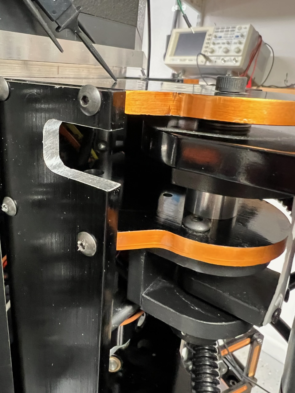
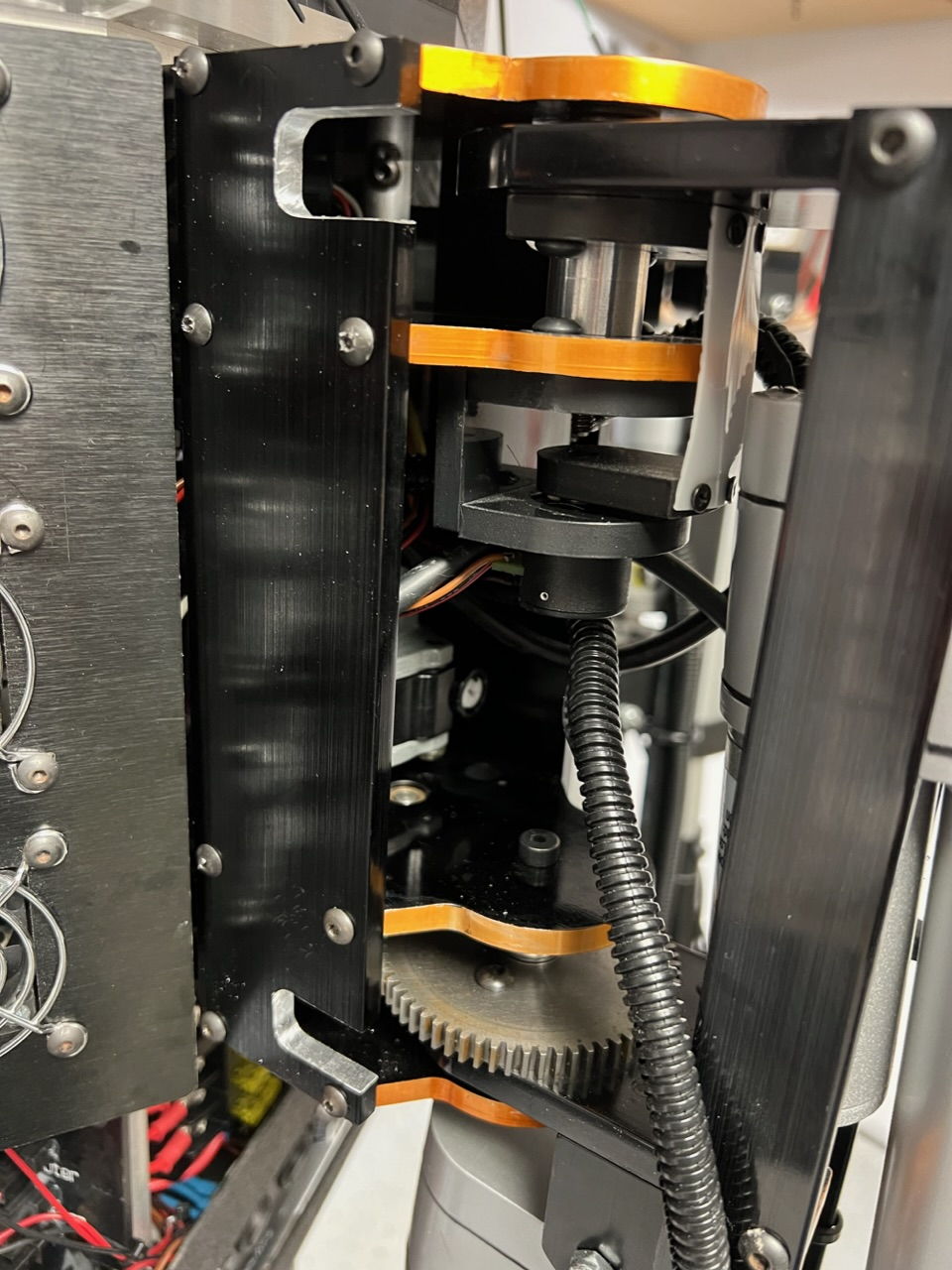
This is a closeup of the upper slot machined on both sides of the leg pivot point.
The next photo shows both slots on a side support.
This will allow the legs to move in 180º arcs vs 120º which will make programming walking easier. Now I have to calibrate the coxa on each leg for the encoder readings at the 0º and 180º positions. I need to pretty up the raw aluminum the milling exposed. Due to the small size of the exposed metal, most likely will use black paint instead of trying to anodize each piece again.
Started to do the calibration for leg #1. I realized that the magnetic encoder is 4096 counts for 360º of motion or 2048 counts for 0 to 180º. Since I know the 90º encoder value, I can just add or subtract 1024 to get pretty close to the 0º and 180º marks. Entered the expected data, put the leg controller in manual mode and told it to go to 0º, it didn’t move… Checking the code I found some error checking I added at some point that if the input value to the coxa was 0, then ignore the command as invalid. Obviously this is no longer true (plus I added other methods to check for valid input values) so that was removed. Now the leg moved but stopped around the 30º mark. I heard a distinct sound of metal striking metal so after a while of looking I realized the tibia motor mount was hitting the side supports (you can see the motor mount in the 2nd photo in the previous entry).
So I removed Leg #1 from the body and moved to the workbench. I removed the coxa motor assembly so I could freely move the leg on the coxa pivot. So I saw some issues that have to be resolved.
1 - The tibia motor mount limits coxa travel, This may require cutting the motor mount back some but the 2 bolts that hold the mount in place may also be in the way of full rotation. Another option is cutting away more of the side support in addition to modifying the motor mount.
2 - All the wires for sensors and motors come in on one side and when the coxa is a 90º, the wires are pinched pretty severely (not a problem at the other extreme of travel as no wires come in from that direction). A possible solution to this pinching is to machine an opening into the side support on the wiring side to allow extra room for the wires.
3 - The magnetic encoder setup for the coxa has a slight interference at the 2 extremes of travel which will require a slight modification to a coupler (make it about an 1.8” narrower).
This has turned into a much bigger job than I anticipated, should have done all this mechanical testing on the bench first before making the slots (although the slots will work as expected, I should have figured out the total scope of the ‘enhancement’ earlier! Going to take some time to figure this out and make sure I’m not introducing any other issues if I make these changes.
Leg 1 has been modified and is reinstalled and ready to test the changes. In the photo you can see most of the changes (just look for the raw aluminum). The slot on the top allows full 180º rotation. The bottom slot had to be cut out because of the coxa motor mount below. I didn’t modify the motor mount since that would have interfered with the mounting bolts on it. The bottom leg support was also cut more to allow full rotation. In the middle of the side support is a 1/2” x 2” cutout to allow the wires access to the robot body without getting pinched at 0º and 180º. I have to zip tie the wire bundles again so that they use the slot. I tried to re-route the wires but as I cut the wires to length for this position, any other spot meant I had to put in new wires or lengthen the existing wires. I also had to drill and tap new mounting holes on the side support piece.
As long as I had the leg in pieces I decided to go ahead and modify the wire routing of the leg touch sensor. Originally it passes up through the lower leg tube which looks great but because of the way the tube is held in place, the wire gets twisted and the wire insulation has gotten damaged. I drilled a 0.4” hole in the back side of the tube which is where the wire comes out now (instead of the other hole just a bit further up on the photo). This keeps the wire from being twisted when the leg down sensor is being screwed into the lower leg tube.
Start testing the changes after dinner and make sure everything works before I start changing the other 5 legs!
Bob Sweeney
Looking at this whole thing… i’m just like WOW! Mad skills!
Thanks!
Finished up modifications to 3 legs, hopefully get the other 3 done tomorrow. I did test the modifications on leg #1 and it worked as expected.
The drive shaft support plates; from the pic, at least the bottom one appears to not be recessed (pocketed) in the side plate and therefore reliant on screw retainers for alignment (?)
Craig
Correct, the side supports are not pocketed and rely on the screws for alignment. The hole tolerances are pretty tight so to keep the parts perpendicular to each other. Further more the bottom and top plates are bolted into the robot body which also helps keep the frame rigid. The movable part of the leg is machined using pockets in the side supports as the screws are only 0.75 inch apart so pocketing improves the rigidity of the part.
I just get a "it's gonna twist" feeling. Easily remedied by banging a few dowels in there. Retainers are only intended to retain.
Craig
The leg is a very solid structure, it weighs in at around 26 lbs! The only flexing I am seeing is the lower leg extension where the leg goes to the ground. That part is a 1” round aluminum tube that is 12” long. So there is some flexing at the leg tip but that helps take up some of the motor movements since each motor moves its part of the leg at different speeds. I haven’t seen any indication that parts are going out of alignment in any of my testing, both on and off the test stand. There is also a lot of bracing that isn’t fully evident in the photos that keeps the parts that need to be rigid in alignment.
I usually get my wrist slapped for critiquing, so I'll drop it.
Craig