@jmg said:
The CS4344 family differs by Serial Audio format as follows:
• CS4344 — 16- to 24-bit, I²S
• CS4345 — 16- to 24-bit, Left-Justified
• CS4348 — 16-bit, Right-Justified
Eeek! Right-justified is broken! It might make some sense if it was also little-endian bit order.
EDIT: Or maybe the CS4348 is little-endian bit order and the documented bit numbering is wrong. I note it's missing the MSB/LSB labels.
It's the same bit order in all three. The "justified" option just means which LRCLK edge the data aligns to. Think of it like word processors "left justified" and "right justified" settings.
Also notice for right justified it only allows 16 bits in this mode, which makes sense.
Also notice for right justified it only allows 16 bits in this mode,
That's broken. May as well truncate the LRCLK while they're at it. I'm suspicious it actually is little-end bit order. That would then stop it being broken.
Ok I see your point now. Yeah I guess it is if you want more than 16 bits and if they claim the part is a 24 bit DAC which they sort of do (although it's a shared datasheet so they can get away with it I suppose). Don't buy the CS4348 for 24 bit applications.
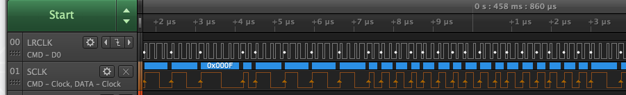
Optical S/PDIF output is working! I can hear the pure sine test tone on my amp.
Here's some biphase mark encoded data captured. The "LRCLK" label is for the 5.6448 MHz transmit clock source and the "SCLK" is the actual SPDIF output. Forget the weird timing quantization of the clock in the capture, it is a proper 50% duty cycle in reality.
Attached are my changes to Micah's code to work with my S/PDIF board. In the end it was quite simple to port this code to the P2 and use the smart pins instead of the video generator. Just some pin init changes really, and you do a WYPIN instead of the WAITVID. The rest is mostly unchanged apart from removing the NR modifier flag use. I did add an optional COGATN feature too for signalling the next sample could be written. Probably should make that customizable to notify the COG(s) after a given buffer size has been read. For higher performance it could also use the RFLONG instead of RDLONG if a fifo buffer is setup, but it doesn't really need to.
For now only 48 and 44.1kHz sample rates are supported. In the future I could potentially get 32kHz going with an internal clock perhaps, but that is subject to jitter if the P2 clock frequency is not a nice multiple of 4.096MHz. That is why I fitted an external clock/PLL on my board, although right now it is limited to either 48 or 44.1kHz operation.
EDIT: Actually I can divide my 24.576MHz clock by 6 to get proper 32kHz operation
EDIT2: updated file with support for 32kHz sampling rate.
What wil happen if you output a jittery signal? Can you hear/see on the oscilloscope distortions caused by the jitter in the input clock?
For I2S I don't see jitter on the reproduced MCLK signal as it is fed through the P2 directly/asynchronously and sourced by the clock generator which has low jitter. In sync tx mode there is certainly digital signal jitter on the LRCLK and SDIN and SCLK outputs relative to MCLK although having the MCLK jitter free seems to fix this potential issue. The other signals will be sampled by MCLK, so they should remain rock solid inside the DAC. I'll have to try out the internal clock source and see how much jitter that adds and if I can hear it. Didn't see any audio jitter on the scope but I might have to try higher frequencies and/or zoom in more.
I am still a bit concerned about the SPDIF signal however, because the P2 output there driving the LED will have some phase jitter in sync tx mode relative to the stable input clock. It is still frequency locked to that low jitter clock source so over a long interval it's pretty stable, perhaps my amp's DAC buffers and reclocks its input to compensate for some amount of jitter like this, I'm not sure. I've not heard it as any warbling or noisy test tone, but I'm probably not a golden ear type so perhaps I didn't notice it yet. I'll need to check further there with headphones. A spectrum analyser could be useful here.
Just tried an internal 5.6448MHz clock source (using NCO FREQ mode) on a 252MHz P2 for the S/PDIF tx clock feeding into my THX certified Z-5500 amp which is nearby and listening on some Sony MDR headphones at high levels. This seemed to sound just as clean in my headphones with the pure tone vs the version with my externally sourced clock. I think any S/PDIF jitter that results is somehow being compensated for by my AMP, or I just can't notice it with my hearing these days. I should try it out with my Marantz amp too if I drag this setup over there, maybe that'll sound different. Probably only golden ears can differentiate this stuff.
It's weird, if you focus in on a single tone for long enough you start to imagine you are hearing things like the tone pulsing etc. Pretty sure it's just imaginary though.
Update: Hmm, weird. If I change to a square wave source data generator instead of a simple sine source and running with the internal generated clock I don't get any output on my amp, it remains muted. With the external clock source I do get output, so maybe the DAC is having a harder time retiming with a square wave...?
Today I was able to hook the S/PDIF audio output with some SD card reading and played back a converted WAV file from my library. Sounds pretty decent to me.
Here's some really simple double buffered playback test code I hacked up for flexspin. Uses the prior posted S/PDIF driver file I ported to it.
CON
    _clkfreq = 100000000

    HEAPSIZE = 32768
    BASE_PIN = 0 ' base pin of S/PDIF board
    RATE = 44100 ' hardcoded for now, should really come from Wave file

OBJ
   c    :"libc.a"               ' C standard library
   f    :"ers_fmt"
   spdif:"spdif"
   uart :"SmartSerial"


PUB main() : err | handle, fileLength
    uart.start(115200)
    send :=@uart.tx

    ' mount card
    send("Mounting SD card",13,10)
    err := _mount(@"/sd", c._vfs_open_sdcard())

    ' begin
    ifnot err
        handle := c.fopen(@"/sd/testwav.wav",@"rb") ' open some given WAV file
        ifnot handle
            send("File open error!",13,10)
        else
            if c.fread(@headerBuf, 44, 1, handle) < 44
                send("File missing WAV header!",13,10)
            else
                ' rudimentary WAVE file header check
                headerBuf[15]:=0 ' terminate string
                if long[@headerBuf][0]<>$46464952 or (strcomp(@headerBuf[8], @"WAVEfmt") <> -1) ' RIFF and WAVEfmt
                    send("Not a RIFF+WAVE file",13,10)
                else
                    ' read file length
                    fileLength := long[@headerBuf][10]
                    send("Starting audio playback, file length = ",f.dec(fileLength)," bytes",13,10)
                    send("Playing time is ", f.dec(fileLength/(60*RATE*4)),":",f.dec(fileLength/(RATE*4) // 60),13,10)
                    player(handle, fileLength)
                    send("Done",13,10)

            c.fclose(handle)
    else
        send("SD mount error!",13,10)
    repeat


PUB player(handle, fileLength) | playHead, pos, bank, elapsed
    playHead := 0
    pos := 0
    bank := 0

    ' setup S/PDIF channel status
    case RATE
        48000: spdif.setChannelStatus(spdif.HZ_48000)
        44100: spdif.setChannelStatus(spdif.HZ_44100)
        32000: spdif.setChannelStatus(spdif.HZ_32000)

    ' setup the S/PDIF sample buffer
    spdif.setBuffer(@spdifBuf, $10000)

    'prefill buffer to begin
    pos := c.fread(@spdifBuf, $10000, 4, handle)
    if pos <> $40000
        send(f.dec(pos),"Not enough data to begin",13,10)
        return

    ' start S/PDIF output
    spdif.start(BASE_PIN, 0) ' no ATN needed

    ' main playback loop feeding data from SD
    repeat while pos >= $20000
        playHead:= spdif.GetCount() & $8000
        'wait until 32k more samples have been read
        if playHead <> bank

            ' check if we are reading samples fast enough
            elapsed := getct()

            'read in next data chunk
            pos := c.fread(@long[@spdifBuf][bank], $8000, 4, handle)

            elapsed := getct()-elapsed
            if elapsed > muldiv64($8000, clkfreq, RATE)
                send("!")

            bank ^= $8000

    ' shutdown and mute output
    longfill(@spdifBuf, 0, $10000) ' bit abrupt for now, but whatever


DAT
headerBuf   byte 0[44]      ' place for wave file header
spdifBuf    long 0[$10000]  ' provides at least a second of audio buffer
@evanh said:
So it's all done with a single shifter, on the SCLK pin, by the looks.
Actually for S/PDIF output mode I make use of 3 P2 IO pins... the MCLK input pin from my clock generator chip (22.5792/24.576MHz), an MCLK output which is a divide by 4 or 6 from the MCLK input pin (again using tx sync mode) to generate the transmit clock required at 4.096/5.6448/6.144MHz, and my SCLK pin which feeds the biphase mark encoded data to the LED inside the 3.5mm connector. Working nicely. Cool thing is the actual P2 frequency can remain independent of this all and be set to anything - well probably something at least above ~50MHz or so.
Thinking about putting a P2 inside an old PVR case I still have laying about to make a P2 controlled music machine to feed a CD library to a HT Hifi amp/projector etc, and/or do P2 video experimenting in general from this box.
Back panel connections would suit the P2 A/V capabilities quite nicely. I'd probably replace the tuner stuff with other ports like PS/2 or something for midi, maybe an external Wifi antenna or RJ45 for Ethernet. Maybe add a couple of joystick ports for some game emulator fun too...
@evanh said:
So it's all done with a single shifter, on the SCLK pin, by the looks.
Actually for S/PDIF output mode I make use of 3 P2 IO pins... the MCLK input pin from my clock generator chip (22.5792/24.576MHz), an MCLK output which is a divide by 4 or 6 from the MCLK input pin (again using tx sync mode) to generate the transmit clock required at 4.096/5.6448/6.144MHz, and my SCLK pin which feeds the biphase mark encoded data to the LED inside the 3.5mm connector. Working nicely. Cool thing is the actual P2 frequency can remain independent of this all and be set to anything - well probably something at least above ~50MHz or so.
Err, sorry, I was in a rush and didn't write a complete sentence. I meant I had no idea what signals control the SPDIF optical transmitter. It's very tidy that a single pin is all that's used to control that component. More compact than I2S even.
Do you have documentation for SPDIF bit stream, or whatever that's called?
@evanh said:
Do you have documentation for SPDIF bit stream, or whatever that's called?
Nothing more than can be googled for the framing etc. All of this work was done by scanlime for P1 and there is good information in this link. I just tweaked that code a little for P2 and my pin setup. https://scanlime.org/2011/04/spdif-digital-audio-on-a-microcontroller/
There is a bunch of other stuff in the 192 bit channel status data but that is hidden in some pay only IEC type document. Apparently you don't need to muck with it apart from the handful of bits the code is already defining, so I didn't care too much about it. It just worked.
I wonder what happens if the data is clocked at a frequency notably off the specified bit rate. Say a stable overclock of 5% for example. I guess it probably isn't defined.
It seems to me the receivers are probably going to be phase locked to the incoming encoded optical clock. Or at least the decode to DAC will be. The alternative is an always-on digital resampling operation. Which would need large buffers and a lot of compute.
@evanh said:
I wonder what happens if the data is clocked at a frequency notably off the specified bit rate. Say a stable overclock of 5% for example. I guess it probably isn't defined.
I think it would be receiver dependent. Although I just tried it out for fun - I output the S/PDIF data with a 6MHz NCO tx clock derived from a 60MHz P2 instead of the expected 5.6448MHz. It played on my Logitech 5500, but somewhat too fast and the pitch was off. So I think this result means there could indeed be jitter if you start to vary the clock in this case.
EDIT: might be fun to ramp the NCO output frequency up and down a bit and see what happens...
Cool, so if the source sample data was at a matching sample rate the pitch would be right and all would be good. Now the question is how far off the spec'd rate is too far? Could it do any sample rate below an upper limit?
32 bits per frame, Two channel frames for stereo, Biphase encoding doubles the bit density again. So 128 bit times per stereo sample. Max of 16e6 / 128 = 125k Samples/s. Hehe, I guess most receivers ain't gonna go anywhere near that.
@evanh said:
Cool, so if the source sample data was at a matching sample rate the pitch would be right and all would be good. Now the question is how far off the spec'd rate is too far? Could it do any sample rate below an upper limit?
I should hook up my absolute encoder to alter the output frequency and try it out... (digital pitch bend lol). Later perhaps.
Yeah I'm using this part from those guys: FCR684204T
Interestingly the max jitter is specified at 15ns for this transmitter. That's probably about the same as operating the P2 at 66MHz and outputting the data at the nearest P2 clock after the actual edge is detected on the input pin. So I guess you won't really hear jitter at that small level. I'm wondering what level you would need it to be to be audibly detectable.
This article claims that jitter is detectable at above 20 picoseconds! Wow. My S/PDIF setup would be a lot worse than that (more like 10ns) so it should be detectable. I think I need to run a test tone at 11025Hz and crank it up more to hear it - just don't want to deafen myself with headphones though! I also need a way to get jitter below this if I want an A/B comparison (maybe run it synchronously locked to the P2 clock, although the P2 system clock itself would have PLL jitter).
It's phase locked, there is no added aliasing. With that, the PLL and buffers will filter out all high frequency jitter. I'm pretty certain only the audio in-band warbling (frequency shifts) can pass. That said, a clock source with rubbish stability will have lower in-band frequency components in it too.
EDIT: Oh, reading that link, I now see he's talking about the control and design of the ADC/DAC converters. Not a difference in digital clocks. Obviously, with pre-recorded PCM sample data, you have to accept any error incurred at recording time. And the receiver's DAC is somewhat decoupled from the SPDIF's bit timings.
EDIT2: But I guess low error jitter at lower frequencies (introduced from an unstable clock) is just as possible as at higher frequencies now I think about it.
Hehe, his reason about 16-bit recordings not being good enough for recording/mixing/production doesn't gel. He says that the 16-bit maths is the flaw. Well of course but intermediate processing has never been limited to 16-bit maths. It would have to be a seriously poorly written program that did the maths in only 16-bit.
One thing I'm thinking is if I ever respin that board I could add a flip flop circuit clocked at the MCLK input rate from the PLL clock synth. That would clean up jitter from the P2 sync tx stage and retime all signals at the master clock rate. This could be applied to the LRCLK, SCLK and SDIN outputs. I think this could help. Would just have to make sure that setup/hold times are not violated to ensure no metastability.
I personally think Prop2's sysclock is plenty stable enough. And the PLL can be programmed close enough to ideal set frequency (158MHz / 28 = 5.643 MHz) using a tidy modeset of 20 MHz / 10 * 79 / 28. EDIT: Err, I guess some multiple above that would be better. Just run the Prop2 at 158 MHz I guess.
@evanh said:
I personally think Prop2's sysclock is plenty stable enough. And the PLL can be programmed close enough to ideal set frequency (158MHz / 28 = 5.643 MHz) using a tidy modeset of 20 MHz / 10 * 79 / 28. EDIT: Err, I guess some multiple above that would be better. Just run the Prop2 at 158 MHz I guess.
Hmm, there's definitely a difference in PLL performance depending on its multiplier and divider values.
But at this stage I'm not clear on how to interpret the jitter I'm seeing on the scope. For example, the same signal captured with three values of one settings (The Post-Trigger Delay) on the scope:
That was 242.727 MHz sysclock using XIN divider of 22 and multipler of 267. Now compare those snapshots to the equivalent using a known stable 240 MHz sysclock (Divider 1, multiplier 12).
The two 240 MHz snapshots look amazingly the same as each other! I'm impressed the scope works that well over such a large relative time.
I don't really know what it means in terms of the information though. Am I sort of performing a Goertzel like tuned sampling of the jitter? And if so, does winding up the scope's delay parameter have an unwanted effect?
PS: All testing is with an Eval Board, revB. I am currently without my PropPlug so can't do the tests with my Edge Card, but the 240 MHz results suggest the Eval Board's crystal is plenty stable enough anyway.
I think that is to be expected. As you increase the delay from the trigger point the clock jitter will effectively be multiplied and more easily observed. A "better" PLL setting will reduce the jitter. 240MHz is an exact multiple of the 20MHz crystal, so I'd expect it should be cleaner.
Later today I hope to try out the S/PDIF from an internal tx clock derived from a clean xtal multiple like this. I hope if I create a low amplitude ~11.025 kHz waveform and output it with this clock and then try the same with the clock from the on board clock synth sampled by the P2 to derive a tx clock, then I could find out if I can hear any difference....
Had an idea regarding coaxial S/PDIF from the P2 (vs optical). The P2 A/V board has a 1uF capacitively coupled input for the microphone jack to a P2 IO pin. But this jack can also be used as an output if we want. If it's sourced by a 75 ohm P2 DAC at levels expected by receivers (in bitDAC mode), I expect we should be able to use it to generate biphase mark encoded data (at least with an internal clock) and feed S/PDIF signals to a receiver. If this works it would be a very good use of the A/V board, as you could do both analog and digital audio and VGA from the same board! A lot of people would already have this board and not all would necessarily be using the microphone input all the time (or at all like me).
I've made up a simple RCA to mono 3.5mm plug to test it out, although you could probably just use a typical stereo 3.5mm to dual RCA cable and use the left channel (tip/white) to feed an amp input. It's not coax (it's just screened two core cable) but it might still work for short runs...otherwise I can make up 75ohm coax version to see if that helps. Will try it soon.
Update:
The way the current S/PDIF driver code works is that you need a tx clock pin defined for the serial tx sync mode smart pin. The microphone pin on the A/V board is at IObase+5. Therefore you'd need to have a tx clock within +/- 3 pins away from this pin. Fine if you don't want VGA or analog audio but if you want them you'd need the clock put at IObase+8. This means that you burn a pin of the next 8 P2 pins. So putting IObase at pin 48 for your A/V board would make a lot of sense on the P2-EVAL if you don't have any breakouts fitted on P56-P63.
Another way could be to use the streamer and have the driver render it's biphase mark encoded data back into HUB RAM and stream from there to a pin at the NCO streamer rate defined with SETXFRQ. This avoids the extra tx clock pin but potentially introduces even more jitter if the NCO setting is not a nice unrounded fraction of $80000000.


Comments
Eeek! Right-justified is broken! It might make some sense if it was also little-endian bit order.
EDIT: Or maybe the CS4348 is little-endian bit order and the documented bit numbering is wrong. I note it's missing the MSB/LSB labels.
It's the same bit order in all three. The "justified" option just means which LRCLK edge the data aligns to. Think of it like word processors "left justified" and "right justified" settings.
Also notice for right justified it only allows 16 bits in this mode, which makes sense.
That's broken. May as well truncate the LRCLK while they're at it. I'm suspicious it actually is little-end bit order. That would then stop it being broken.
Ok I see your point now. Yeah I guess it is if you want more than 16 bits and if they claim the part is a 24 bit DAC which they sort of do (although it's a shared datasheet so they can get away with it I suppose). Don't buy the CS4348 for 24 bit applications.
Optical S/PDIF output is working! I can hear the pure sine test tone on my amp.
Here's some biphase mark encoded data captured. The "LRCLK" label is for the 5.6448 MHz transmit clock source and the "SCLK" is the actual SPDIF output. Forget the weird timing quantization of the clock in the capture, it is a proper 50% duty cycle in reality.
Attached are my changes to Micah's code to work with my S/PDIF board. In the end it was quite simple to port this code to the P2 and use the smart pins instead of the video generator. Just some pin init changes really, and you do a WYPIN instead of the WAITVID. The rest is mostly unchanged apart from removing the NR modifier flag use. I did add an optional COGATN feature too for signalling the next sample could be written. Probably should make that customizable to notify the COG(s) after a given buffer size has been read. For higher performance it could also use the RFLONG instead of RDLONG if a fifo buffer is setup, but it doesn't really need to.
For now only 48 and 44.1kHz sample rates are supported. In the future I could potentially get 32kHz going with an internal clock perhaps, but that is subject to jitter if the P2 clock frequency is not a nice multiple of 4.096MHz. That is why I fitted an external clock/PLL on my board, although right now it is limited to either 48 or 44.1kHz operation.
EDIT: Actually I can divide my 24.576MHz clock by 6 to get proper 32kHz operation
EDIT2: updated file with support for 32kHz sampling rate.
What wil happen if you output a jittery signal? Can you hear/see on the oscilloscope distortions caused by the jitter in the input clock?
For I2S I don't see jitter on the reproduced MCLK signal as it is fed through the P2 directly/asynchronously and sourced by the clock generator which has low jitter. In sync tx mode there is certainly digital signal jitter on the LRCLK and SDIN and SCLK outputs relative to MCLK although having the MCLK jitter free seems to fix this potential issue. The other signals will be sampled by MCLK, so they should remain rock solid inside the DAC. I'll have to try out the internal clock source and see how much jitter that adds and if I can hear it. Didn't see any audio jitter on the scope but I might have to try higher frequencies and/or zoom in more.
I am still a bit concerned about the SPDIF signal however, because the P2 output there driving the LED will have some phase jitter in sync tx mode relative to the stable input clock. It is still frequency locked to that low jitter clock source so over a long interval it's pretty stable, perhaps my amp's DAC buffers and reclocks its input to compensate for some amount of jitter like this, I'm not sure. I've not heard it as any warbling or noisy test tone, but I'm probably not a golden ear type so perhaps I didn't notice it yet. I'll need to check further there with headphones. A spectrum analyser could be useful here.
Just tried an internal 5.6448MHz clock source (using NCO FREQ mode) on a 252MHz P2 for the S/PDIF tx clock feeding into my THX certified Z-5500 amp which is nearby and listening on some Sony MDR headphones at high levels. This seemed to sound just as clean in my headphones with the pure tone vs the version with my externally sourced clock. I think any S/PDIF jitter that results is somehow being compensated for by my AMP, or I just can't notice it with my hearing these days. I should try it out with my Marantz amp too if I drag this setup over there, maybe that'll sound different. Probably only golden ears can differentiate this stuff.
It's weird, if you focus in on a single tone for long enough you start to imagine you are hearing things like the tone pulsing etc. Pretty sure it's just imaginary though.
Update: Hmm, weird. If I change to a square wave source data generator instead of a simple sine source and running with the internal generated clock I don't get any output on my amp, it remains muted. With the external clock source I do get output, so maybe the DAC is having a harder time retiming with a square wave...?
Today I was able to hook the S/PDIF audio output with some SD card reading and played back a converted WAV file from my library. Sounds pretty decent to me.
Here's some really simple double buffered playback test code I hacked up for flexspin. Uses the prior posted S/PDIF driver file I ported to it.
CON _clkfreq = 100000000 HEAPSIZE = 32768 BASE_PIN = 0 ' base pin of S/PDIF board RATE = 44100 ' hardcoded for now, should really come from Wave file OBJ c :"libc.a" ' C standard library f :"ers_fmt" spdif:"spdif" uart :"SmartSerial" PUB main() : err | handle, fileLength uart.start(115200) send :=@uart.tx ' mount card send("Mounting SD card",13,10) err := _mount(@"/sd", c._vfs_open_sdcard()) ' begin ifnot err handle := c.fopen(@"/sd/testwav.wav",@"rb") ' open some given WAV file ifnot handle send("File open error!",13,10) else if c.fread(@headerBuf, 44, 1, handle) < 44 send("File missing WAV header!",13,10) else ' rudimentary WAVE file header check headerBuf[15]:=0 ' terminate string if long[@headerBuf][0]<>$46464952 or (strcomp(@headerBuf[8], @"WAVEfmt") <> -1) ' RIFF and WAVEfmt send("Not a RIFF+WAVE file",13,10) else ' read file length fileLength := long[@headerBuf][10] send("Starting audio playback, file length = ",f.dec(fileLength)," bytes",13,10) send("Playing time is ", f.dec(fileLength/(60*RATE*4)),":",f.dec(fileLength/(RATE*4) // 60),13,10) player(handle, fileLength) send("Done",13,10) c.fclose(handle) else send("SD mount error!",13,10) repeat PUB player(handle, fileLength) | playHead, pos, bank, elapsed playHead := 0 pos := 0 bank := 0 ' setup S/PDIF channel status case RATE 48000: spdif.setChannelStatus(spdif.HZ_48000) 44100: spdif.setChannelStatus(spdif.HZ_44100) 32000: spdif.setChannelStatus(spdif.HZ_32000) ' setup the S/PDIF sample buffer spdif.setBuffer(@spdifBuf, $10000) 'prefill buffer to begin pos := c.fread(@spdifBuf, $10000, 4, handle) if pos <> $40000 send(f.dec(pos),"Not enough data to begin",13,10) return ' start S/PDIF output spdif.start(BASE_PIN, 0) ' no ATN needed ' main playback loop feeding data from SD repeat while pos >= $20000 playHead:= spdif.GetCount() & $8000 'wait until 32k more samples have been read if playHead <> bank ' check if we are reading samples fast enough elapsed := getct() 'read in next data chunk pos := c.fread(@long[@spdifBuf][bank], $8000, 4, handle) elapsed := getct()-elapsed if elapsed > muldiv64($8000, clkfreq, RATE) send("!") bank ^= $8000 ' shutdown and mute output longfill(@spdifBuf, 0, $10000) ' bit abrupt for now, but whatever DAT headerBuf byte 0[44] ' place for wave file header spdifBuf long 0[$10000] ' provides at least a second of audio bufferThat sounds real spiffy.
So it's all done with a single shifter, on the SCLK pin, by the looks.
Actually for S/PDIF output mode I make use of 3 P2 IO pins... the MCLK input pin from my clock generator chip (22.5792/24.576MHz), an MCLK output which is a divide by 4 or 6 from the MCLK input pin (again using tx sync mode) to generate the transmit clock required at 4.096/5.6448/6.144MHz, and my SCLK pin which feeds the biphase mark encoded data to the LED inside the 3.5mm connector. Working nicely. Cool thing is the actual P2 frequency can remain independent of this all and be set to anything - well probably something at least above ~50MHz or so.
Thinking about putting a P2 inside an old PVR case I still have laying about to make a P2 controlled music machine to feed a CD library to a HT Hifi amp/projector etc, and/or do P2 video experimenting in general from this box.
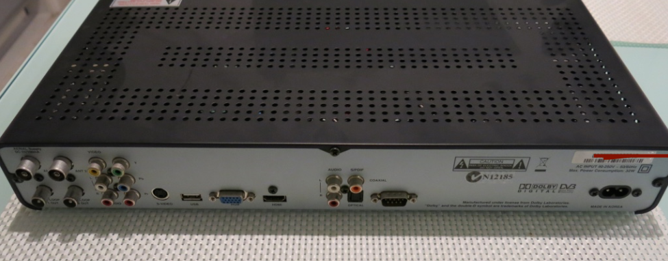
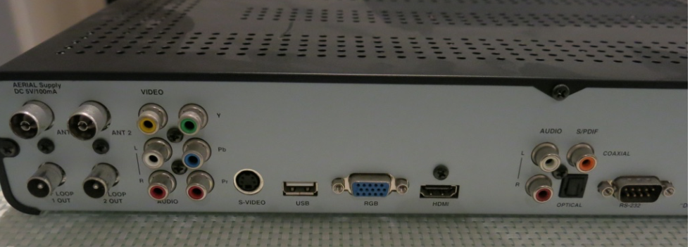
Back panel connections would suit the P2 A/V capabilities quite nicely. I'd probably replace the tuner stuff with other ports like PS/2 or something for midi, maybe an external Wifi antenna or RJ45 for Ethernet. Maybe add a couple of joystick ports for some game emulator fun too...
Front panel has a UART controlled alphanumeric VFD and IR receiver I could potentially hack into and several buttons for song selection, or menu controls etc. Someone's already hacked it here too by the looks of it...
https://hackaday.com/2021/08/14/reverse-engineering-a-topfield-vfd-front-panel/
Err, sorry, I was in a rush and didn't write a complete sentence. I meant I had no idea what signals control the SPDIF optical transmitter. It's very tidy that a single pin is all that's used to control that component. More compact than I2S even.
Do you have documentation for SPDIF bit stream, or whatever that's called?
Nothing more than can be googled for the framing etc. All of this work was done by scanlime for P1 and there is good information in this link. I just tweaked that code a little for P2 and my pin setup.
https://scanlime.org/2011/04/spdif-digital-audio-on-a-microcontroller/
There is a bunch of other stuff in the 192 bit channel status data but that is hidden in some pay only IEC type document. Apparently you don't need to muck with it apart from the handful of bits the code is already defining, so I didn't care too much about it. It just worked.
I wonder what happens if the data is clocked at a frequency notably off the specified bit rate. Say a stable overclock of 5% for example. I guess it probably isn't defined.
It seems to me the receivers are probably going to be phase locked to the incoming encoded optical clock. Or at least the decode to DAC will be. The alternative is an always-on digital resampling operation. Which would need large buffers and a lot of compute.
I think it would be receiver dependent. Although I just tried it out for fun - I output the S/PDIF data with a 6MHz NCO tx clock derived from a 60MHz P2 instead of the expected 5.6448MHz. It played on my Logitech 5500, but somewhat too fast and the pitch was off. So I think this result means there could indeed be jitter if you start to vary the clock in this case.
EDIT: might be fun to ramp the NCO output frequency up and down a bit and see what happens...
Cool, so if the source sample data was at a matching sample rate the pitch would be right and all would be good. Now the question is how far off the spec'd rate is too far? Could it do any sample rate below an upper limit?
Just been looking at some TOSLINK jacks and note they're rated up to 16 Mbit/s at 20 metres - https://www.cliffuk.co.uk/products/optical/opticaljacks.htm
32 bits per frame, Two channel frames for stereo, Biphase encoding doubles the bit density again. So 128 bit times per stereo sample. Max of 16e6 / 128 = 125k Samples/s. Hehe, I guess most receivers ain't gonna go anywhere near that.
I should hook up my absolute encoder to alter the output frequency and try it out... (digital pitch bend lol). Later perhaps.
Yeah I'm using this part from those guys: FCR684204T
Interestingly the max jitter is specified at 15ns for this transmitter. That's probably about the same as operating the P2 at 66MHz and outputting the data at the nearest P2 clock after the actual edge is detected on the input pin. So I guess you won't really hear jitter at that small level. I'm wondering what level you would need it to be to be audibly detectable.
This article claims that jitter is detectable at above 20 picoseconds! Wow. My S/PDIF setup would be a lot worse than that (more like 10ns) so it should be detectable. I think I need to run a test tone at 11025Hz and crank it up more to hear it - just don't want to deafen myself with headphones though! I also need a way to get jitter below this if I want an A/B comparison (maybe run it synchronously locked to the P2 clock, although the P2 system clock itself would have PLL jitter).
https://benchmarkmedia.com/blogs/application_notes/13124137-the-unique-evils-of-digital-audio-and-how-to-defeat-them
It's phase locked, there is no added aliasing. With that, the PLL and buffers will filter out all high frequency jitter. I'm pretty certain only the audio in-band warbling (frequency shifts) can pass. That said, a clock source with rubbish stability will have lower in-band frequency components in it too.
EDIT: Oh, reading that link, I now see he's talking about the control and design of the ADC/DAC converters. Not a difference in digital clocks. Obviously, with pre-recorded PCM sample data, you have to accept any error incurred at recording time. And the receiver's DAC is somewhat decoupled from the SPDIF's bit timings.
EDIT2: But I guess low error jitter at lower frequencies (introduced from an unstable clock) is just as possible as at higher frequencies now I think about it.
Hehe, his reason about 16-bit recordings not being good enough for recording/mixing/production doesn't gel. He says that the 16-bit maths is the flaw. Well of course but intermediate processing has never been limited to 16-bit maths. It would have to be a seriously poorly written program that did the maths in only 16-bit.
One thing I'm thinking is if I ever respin that board I could add a flip flop circuit clocked at the MCLK input rate from the PLL clock synth. That would clean up jitter from the P2 sync tx stage and retime all signals at the master clock rate. This could be applied to the LRCLK, SCLK and SDIN outputs. I think this could help. Would just have to make sure that setup/hold times are not violated to ensure no metastability.
I personally think Prop2's sysclock is plenty stable enough. And the PLL can be programmed close enough to ideal set frequency (158MHz / 28 = 5.643 MHz) using a tidy modeset of 20 MHz / 10 * 79 / 28. EDIT: Err, I guess some multiple above that would be better. Just run the Prop2 at 158 MHz I guess.
EDIT2: Oh, got a better one: 254 MHz / 45 = 5.6444 MHz. (20 MHz / 10 * 127 = 254 MHz)
254 MHz is close to 252 MHz for DVI/HDMI video.
Increasingly accurate:
20 MHz * 267 / 22 = 242.72 MHz, / 43 = 5.644820 MHz
20 MHz * 383 / 59 = 129.83 MHz, / 23 = 5.644804 MHz
20 MHz * 499 / 68 = 146.76 MHz, /26 = 5.644796 MHz
20 MHz * 499 / 52 = 191.92 MHz, /34 = 5.644796 MHz
20 MHz * 499 / 34 = 293.53 MHz, /52 = 5.644796 MHz
20 MHz * 882 / 3125 = 5.6448 MHz exactly but not possible on P2?
Hmm, there's definitely a difference in PLL performance depending on its multiplier and divider values.
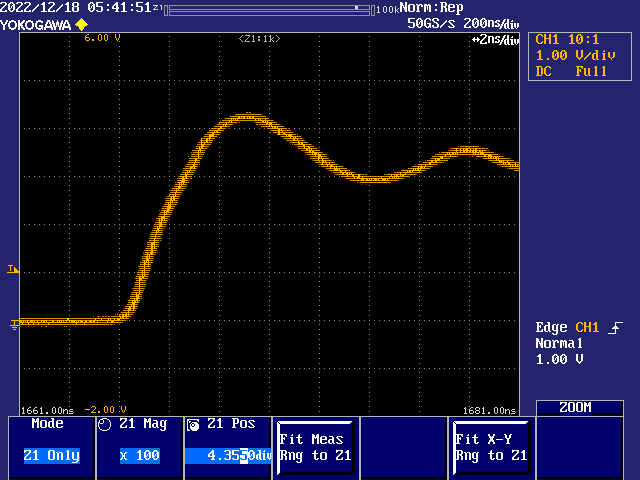
But at this stage I'm not clear on how to interpret the jitter I'm seeing on the scope. For example, the same signal captured with three values of one settings (The Post-Trigger Delay) on the scope:
Delay of 1.648 microseconds:
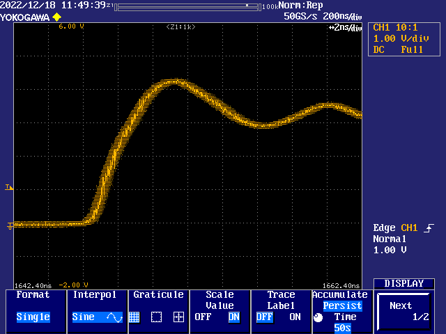
Delay of 4.120 microseconds:
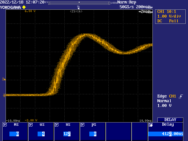
Delay of 15.655 microseconds:
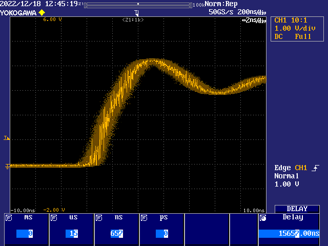
That was 242.727 MHz sysclock using XIN divider of 22 and multipler of 267. Now compare those snapshots to the equivalent using a known stable 240 MHz sysclock (Divider 1, multiplier 12).
Delay of 1.667 microseconds:
Delay of 15.833 microseconds:
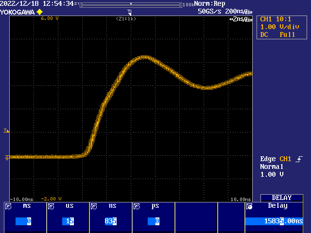
The two 240 MHz snapshots look amazingly the same as each other! I'm impressed the scope works that well over such a large relative time.
I don't really know what it means in terms of the information though. Am I sort of performing a Goertzel like tuned sampling of the jitter? And if so, does winding up the scope's delay parameter have an unwanted effect?
PS: All testing is with an Eval Board, revB. I am currently without my PropPlug so can't do the tests with my Edge Card, but the 240 MHz results suggest the Eval Board's crystal is plenty stable enough anyway.
I think that is to be expected. As you increase the delay from the trigger point the clock jitter will effectively be multiplied and more easily observed. A "better" PLL setting will reduce the jitter. 240MHz is an exact multiple of the 20MHz crystal, so I'd expect it should be cleaner.
Later today I hope to try out the S/PDIF from an internal tx clock derived from a clean xtal multiple like this. I hope if I create a low amplitude ~11.025 kHz waveform and output it with this clock and then try the same with the clock from the on board clock synth sampled by the P2 to derive a tx clock, then I could find out if I can hear any difference....
Had an idea regarding coaxial S/PDIF from the P2 (vs optical). The P2 A/V board has a 1uF capacitively coupled input for the microphone jack to a P2 IO pin. But this jack can also be used as an output if we want. If it's sourced by a 75 ohm P2 DAC at levels expected by receivers (in bitDAC mode), I expect we should be able to use it to generate biphase mark encoded data (at least with an internal clock) and feed S/PDIF signals to a receiver. If this works it would be a very good use of the A/V board, as you could do both analog and digital audio and VGA from the same board! A lot of people would already have this board and not all would necessarily be using the microphone input all the time (or at all like me).
Wikipedia says it should be 0.5-0.6Vpk-pk.
https://en.wikipedia.org/wiki/S/PDIF
I've made up a simple RCA to mono 3.5mm plug to test it out, although you could probably just use a typical stereo 3.5mm to dual RCA cable and use the left channel (tip/white) to feed an amp input. It's not coax (it's just screened two core cable) but it might still work for short runs...otherwise I can make up 75ohm coax version to see if that helps. Will try it soon.
Update:
The way the current S/PDIF driver code works is that you need a tx clock pin defined for the serial tx sync mode smart pin. The microphone pin on the A/V board is at IObase+5. Therefore you'd need to have a tx clock within +/- 3 pins away from this pin. Fine if you don't want VGA or analog audio but if you want them you'd need the clock put at IObase+8. This means that you burn a pin of the next 8 P2 pins. So putting IObase at pin 48 for your A/V board would make a lot of sense on the P2-EVAL if you don't have any breakouts fitted on P56-P63.
Another way could be to use the streamer and have the driver render it's biphase mark encoded data back into HUB RAM and stream from there to a pin at the NCO streamer rate defined with SETXFRQ. This avoids the extra tx clock pin but potentially introduces even more jitter if the NCO setting is not a nice unrounded fraction of $80000000.