

Require specific Guide/Manual for Propeller 2 GPIO coding in c/c++
 chintan_joshi
Posts: 135
chintan_joshi
Posts: 135
in C/C++
Hello Everyone,
I am embedded c/c++ developer and new to this site and just bought Propeller 2. I want to start with high frequency GPIO code using c++. But not able to find proper guide or user manual to start with Propeller 2. So it will be helpful if someone can provide link/document for Propeller2 GPIO coding using c++?
Comments
Most of your work will be getting familiar with the environment.
Lots of good links here - https://forums.parallax.com/discussion/173000/propeller-2-users-get-started-here/p1
Definitive hardware reference document is still Chip's silicon google doc - https://docs.google.com/document/d/1gn6oaT5Ib7CytvlZHacmrSbVBJsD9t_-kmvjd7nUR6o/edit?usp=sharing
And also at the end of his Spin2 doc, it defines common used compile time symbols - https://docs.google.com/document/d/16qVkmA6Co5fUNKJHF6pBfGfDupuRwDtf-wyieh_fbqw/edit
There is two third-party C compilers:
EDIT: Changed Catalina link
Here's a list from the FlexC manual for bit-bashing functions:
Thank you very much for the support. Let me check all this.
If you are looking for C++ specifically, I will plug my clang port as well: https://forums.parallax.com/discussion/171962/llvm-backend-for-propeller-2/p1
I have an (incomplete) smart pin library I am working on that I can point you to do some basic stuff, but it’s not documented yet.
Hy @Nikita, Thank you for pointing out p2llvm library. Currently i am working on to just build normal c code and access GPIO to get understanding of Propeller 2. Once i finish this i will be in better position to decide library to port my existing c++ code to Propeller 2 supported code.
Hello , Is there any specific library/ Sample code available for UART in c/c++ for propeller 2 Flexprop ide? i want to transmit image raw data from Raspberry pi to Propeller 2 on high speed. I have checked simpletools.h but there is no functions for UART imterface.
Also another thing is i want to make multiple GPIO pins high/LOW at same time , same like write to Port. I have used **set_outputs(End Pin, Start pin, 0b00111100); ** But this taking more time. I want to do it on faster way(In nano seconds). So is there any alternative available to write multiple pins at same time in high speed?
You'll inevitably be ending up with some inline assembly ... here's my super simple diag routines for sending text to terminal. It's written in Spin2 because FlexC can compile and integrate Spin natively. Therefore it is more portable for use with the wider Propeller community.
CON
    DIAGTXPIN = 62
    DIAGRXPIN = 63


PUB  baudinit( baud ) | x
    x := muldiv65( 64, clkfreq, baud ) << 10 | 7
    pinstart( DIAGTXPIN, P_ASYNC_TX | P_OE, x, 0 )
    pinstart( DIAGRXPIN, P_ASYNC_RX, x, 0 )


PUB  putch( char )
    org
.loop
        rqpin   inb, #DIAGTXPIN   wc    'transmiting? (C high == yes)  *Needed to initiate tx
        testp   #DIAGTXPIN   wz         'buffer free? (IN high == yes)
if_c_and_nz jmp #.loop                  'wait while Smartpin is both full (nz) and transmitting (c)
        wypin   char, #DIAGTXPIN        'write new byte to Y buffer
    end
PS: It makes use of the one-word (a byte by default) hardware buffer.
Oh, and here's the muldiv65():
PUB muldiv65( mult1, mult2, divisor ) : result ' 32bit result = 32bit x 32bit / 32bit ' Rounding to nearest variant of muldiv64() org qmul mult1, mult2 mov result, divisor shr result, #1 getqx mult1 ' lower 32 bits of 64-bit intermediate getqy mult2 ' upper 32 bits of 64-bit intermediate add mult1, result wc ' round-to-nearest addx mult2, #0 ' round-to-nearest setq mult2 qdiv mult1, divisor getqx result endI'm pretty certain the earlier doc I quoted isn't quite giving all the info. Eg: It should read:
The value of
pincan include theaddpinsextension to specify a contiguous pin group. EDIT: Err, ADDPINS is a Spin2 term. It's just an extra bit-field in the pin number, the field of pin[10:6] specifies the number of pins in the group, with zero value meaning a single pin. So, in C, do this:pin = 12 | 3<<6to address the four pins P12..P15.PS; This is a hardware feature. It costs no extra instructions. Every dedicated pin instruction has this ADDPINS ability. Eg:
_pinh(int pin);compiles to a single instruction.Hello @evanh , Need little Help on pin = 12 | 3<<6.
I am using set_outputs like this,
set_outputs(19, 12, hex_t[index][i]);
hex_t[index][i] will have 8 bit hex value, and based on HEX value i am making pins 12 to 19 HIGH/LOW. so some pins will be High and some pins will be LOW.
So how can i assign runtime HEX value to pin variable? Please suggest.
Sounds like you want to place an 8-bit number onto a group of eight parallel pins. To do that bit-bash style the quickest way would be SETBYTE instruction on the OUTA/B registers. It only works on byte aligned boundaries, eg: Pins P8..P15, but most byte wide ops are easiest that way.
The universal way would be using SETQ+MUXQ combo on same registers instead. That's likely what the listed
void _pinwrite(int pins, int val);is doing.For _pinwrite() how can i add pins 12 to 19 in pins variable?
I am fine if i have to use P8 to P15 instead of 12 to 19 if that works.
So kindly share how can i use SETBYTE instruction as well for pins P8 to P15.
Oh, sorry, here:
_pinwrite( 12|7<<6, val ); // write to pins P12..P19Here's a quick hack up of function for using SETBYTE in C:
static void  pinout8( unsigned group, unsigned val )
{
    __asm {
        altsb   group, #0x1fc  // OUTA cog register
        setbyte val
        altsb   group, #0x1fa  // DIRA cog register
        setbyte #0xff
    }
}
PS: This works across OUTB and DIRB too, since they are adjoining registers, 0x1fd and 0x1fb respectively. The prefixing ALTSB instruction indexes across multiple registers.
Thank you very much for your reply @evanh .
Need help for SPI communication as well. For SPI Communication which pins can i use for Propeller2 for MOSI, MISO, CLK and CS? I am not able to find any specific Pins. I have checked schematic and found SD card pins have SPI Labeled.
Found (https://learn.parallax.com/tutorials/language/propeller-c/propeller-c-simple-protocols/spi-example), this link for SPI example but not sure for pins.
So can i use those pins like:
CS: 60
MOSI: 59
MISO : 58
CLK: 61
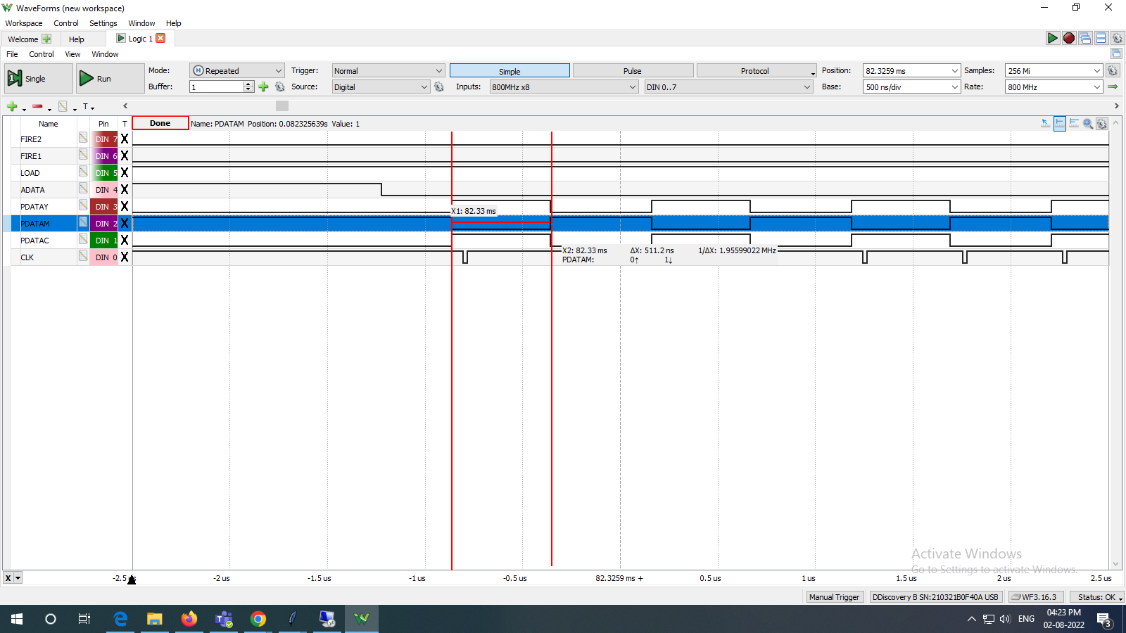
Hello , If i use _pinwrite() function to set/clear group of pins then its taking approax 500 ns, can i make it more fast? or its limitation of propeller2 library?
As per attached screenshot, PDATAC, PDATAM and PDATAY are setting up with _pinwrite() and its taking approax 500 ns.
With P2 smart pins you can use any IO you want for SPI. Sorry, I'm not a C programmer, but I can show you the process in Spin2 -- it will probably be very similar under FlexProp C.
This example doesn't use MISO, but you can set it up and relate it to the SCLK pin as with MOSI (the mode is P_SYNC_RX). The only restriction is that the MOSI and MISO pins need to be within +/- three pins of SCLK.
pub spi_write(value)

  value ror= 8                                                  ' flip MSB/LSB for smart pin
  value rev= 31

  pinl(CSX)                                                     ' select device

  wypin(MOSI, value)                                            ' write value to SPI out
  pinl(MOSI)                                                    ' enable SPI smart pin
  wypin(SCLK, 8)                                                ' clock 8 bits
  repeat until pinr(SCLK)                                       ' let it finish
  pinf(MOSI)                                                    ' reset MOSI smart pin

  pinh(CSX)                                                     ' deselect device


pub pasm_spi_write(value)

  org
                        ror       value, #8                     ' flip MSB/LSB for smart pin
                        rev       value

                        drvl      #CSX                          ' select device

                        wypin     value, #MOSI                  ' write value to SPI out
                        drvl      #MOSI                         ' enable SPI smart pin
                        wypin     #8, #SCLK                     ' clock 8 bits
                        nop                                     ' let it start
                        testp     #SCLK                 wc      ' wait for it to finish
        if_nc           jmp       #$-1

                        fltl      #MOSI                         ' reset SPI smart pin

                        drvh      #CSX                          ' deselect device
  end
To write a byte, load the value into the MOSI pin and enable it, then load SCLK with the number of bits to clock. Reading the IN bit from the SCLK pin will tell you when its finished. Note, too, that the value is always output LSB first from the smart pin, so you may need to flip the bits before transmitting. If CPOL is 1, you can add P_INVERT_OUTPUT to the SCLK configuration bits.
Here's some examples to get a feel for what's possible:
#include <stdint.h> #include <stdio.h> #include <stdlib.h> #include <math.h> #include <sys/time.h> enum { // _xinfreq = 20_000_000, _xtlfreq = 20_000_000, _clkfreq = 4_000_000, DOWNLOAD_BAUD = 230_400, DEBUG_BAUD = DOWNLOAD_BAUD, PINS = 20|7<<6, GROUP = 1, }; static uint32_t pinout8_dma( unsigned pgroup, uint8_t *haddr, unsigned len ) { uint32_t xfrq = 0x8000_0000; // sysclock/1 data rate, top speed! uint32_t m_tx = X_RFBYTE_8P_1DAC8 | pgroup<<20 | X_PINS_ON | len; // byte wide transfers from hubRAM, via the FIFO uint32_t ticks = _cnt(); __asm volatile { // "volatile" enforces Fcache use, which is needed to free up the FIFO rdfast #0, haddr // setup the FIFO to read from hubRAM setxfrq xfrq // set the transfer rate xinit m_tx, #0 // do it! waitxfi // wait for transfer to complete before returning back to hubexec, hubexec uses the FIFO } return _cnt() - ticks; } static uint32_t pinout8_grp( unsigned pgroup, uint8_t *haddr, unsigned len ) { uint8_t val; uint32_t i, ticks = _cnt(); for( i=0; i<len; i++ ) { val = *(haddr++); __asm { //__asm const { altsb pgroup, #0x1fc // OUTA cog register setbyte val } } return _cnt() - ticks; } static uint32_t pinout8_bb( unsigned pins, uint8_t *haddr, unsigned len ) { uint8_t val; uint32_t i, ticks = _cnt(); for( i=0; i<len; i++ ) { val = *(haddr++); _pinwrite( pins, val ); } return _cnt() - ticks; } static uint32_t filldat( uint8_t *haddr, unsigned len ) { uint32_t i, ticks = _cnt(); for( i=0; i<len; i++ ) { *(haddr++) = (uint8_t)(len - i); } return _cnt() - ticks; } void main( void ) { uint8_t buff[1000]; _waitms( 200 ); printf( "\n clkfreq = %d clkmode = 0x%x\n", _clockfreq(), _clockmode() ); printf( "\narray size is %d bytes. filldat() in %d ticks.\n", sizeof(buff), filldat( buff, sizeof(buff) ) ); for(;;) // ever { _pinl( PINS ); printf( "pinout8_bb() in %d ticks. ", pinout8_bb( PINS, buff, sizeof(buff) ) ); _pinf( PINS ); _pinl( GROUP<<3|7<<6 ); printf( "pinout8_grp() in %d ticks. ", pinout8_grp( GROUP, buff, sizeof(buff) ) ); printf( "pinout8_dma() in %d ticks.\n", pinout8_dma( GROUP, buff, sizeof(buff) ) ); _pinf( GROUP<<3|7<<6 ); _waitms( 800 ); }; }Expanded a couple more for demoing the optimiser. FlexC's default is -O1 optimising.
With default
-O1we get:With
-O0 --fcache=128we get:With
-O2we get:Hello @evanh thank you very much for the help. pinout8_dma working very fast. But i am not able to understand the logic behind it. Sorry but It will be very good if you can explain this code to me so i can change this code according to my requirement?
Especially below line.
static uint32_t pinout8_dma( unsigned pgroup, uint8_t *haddr, unsigned len )
{
uint32_t xfrq = 0x4000_0000; // sysclock/1 data rate, top speed!
uint32_t m_tx = X_RFBYTE_8P_1DAC8 | pgroup<<20 | X_PINS_ON | len; // byte wide transfers from hubRAM, via the FIFO
uint32_t ticks = _cnt();
__asm volatile { // "volatile" enforces Fcache use, which is needed to free up the FIFO
rdfast #0, haddr // setup the FIFO to read from hubRAM
setxfrq xfrq // set the transfer rate
xinit m_tx, #0 // do it!
waitxfi // wait for transfer to complete before returning back to hubexec, hubexec uses the FIFO
}
}
Thank you very much for the SPI details. Will surely check this.
The symbols used there are listed in the Spin2 Document. They each pertain to streamer mode setting. The "streamer" is documented in the Silicon Document.
The basic structure of the streamer hardware is a DMA engine that shares the cog's databus to access hubRAM. Each cog has a partnering streamer.
And in front of the databus sits a "FIFO" that performs prefetching on hubRAM reads and buffered write-throughs on hubRAM writes. Certain ops need this FIFO, others don't. The streamer always needs it if accessing hubRAM. Half the DMA engine is this FIFO, since it performs the memory addressing for the streamer.
GROUP can be any value from 0 to 7. It specifies which byte sized pin group you want to place the bytes out on. It is intentionally restricted to the groups supported by the streamer modes. eg: GROUP=2 is pins P16..P23.
Okay, probably should mention why the FIFO needs to exist at all. It's because of the 8-way shared access between the eight cogs. In particular the streamers can't tolerate erratic memory timing.
Underneath all the cog databuses there is a cross-point switching matrix to allow total hubRAM access to all cogs at once. But each cog can only access the same hubRAM bank/slice in its turn/slot. This means there is a 1/8th initial fetch opportunity for each cog. However, once fetching sequential addresses, it can burst read or write at full sysclock to any and all cogs. The mechanism has been dubbed the "eggbeater". And the FIFO makes good use of that burst ability.
Of note is this layer of the eggbeater stacks onto the hubRAM read latency, over and above the 1/8th opportunity. RDFAST instruction can block for 20 sysclock ticks on FIFO filling. The instruction blocking can be skipped if you know there is at least that many ticks between the RDFAST issuing and first use of the FIFO.
I've added one more case to the test program - pinout8_grp3(). It uses the FIFO but not the streamer.
Chintan,
Here's a generic calculation to convert whole clock dividers into NCO fractions for the streamer (SETXFRQ instruction). It performs the needed rounding to initiate first cycle at the correct clock ratio. Otherwise the non-powers-of-two will extend an extra sysclock tick for the first NCO cycle.
CON
    CLK_DIV = 1    ' sysclock/1 data rate, top speed!
    M_NCO = $8000_0000 +/ CLK_DIV + ($8000_0000 +// CLK_DIV > 0 ? 1 : 0)    ' round up
Again it's written in Spin2. The operators are explicitly unsigned (eg: the +// for unsigned remainder), since the only type in Spin is an undefined 32-bit integer.
EDIT: Here's the C version:
enum { CLK_DIV = 1UL, // sysclock/1 data rate, top speed! M_NCO = 0x8000_0000UL / CLK_DIV + (0x8000_0000UL % CLK_DIV > 0UL ? 1UL : 0UL), // round up }Oops, I'd forgotten what "volatile" does. It prevents optimisation, not anything to do with Fcache.
pinout8_grp1()andpinout8_grp2()weren't doing what I thought at all. They were both Fcache'd, just that grp1 got optimised while grp2 didn't.Or not. The testing tells me it's not that simple either.
pinout8_grp2()has a clear speed up. Andpinout8_grp3()is cycling on just three instructions! That can only happen if its loop was optimised into a REP block.I'm thinking volatile's purpose there has changed as FlexC has grown. Docs say:
My guess is the first half of that statement has been revoked.
No, that's just a bug -- there were a few P2 specific optimizations that weren't checking the flag that says the instruction came from user's volatile asm code, and one of them was the DJNZ -> REP optimizatoin. That's fixed in github now.
Okay, cool. Updated my code to match that now. Another case added for a hand optimised REP loop. I've commented the source better now too.
Hello @evanh i have tried to modify code as per my requirement as shown below.
unsigned char d = hex_t[index][i];__asm { // allowed to be optimised and hubexec inlinedaltsb 2, #0x1fc // SETBYTE indirection prefixer, OUTA base cog registersetbyte d // "val" is indexed into 64-bit OUTA/OUTB register pair}_pinw(CLK, 0);_waitx(1);_pinw(CLK, 1);Here i am taking 1 byte from hex_t[index][i]. and setting up pins 16 to 23 using group 2 and loading with falling edge of the clock pin(Shift Register coding). But i am not able to see any change on pins 16 to 23 with these instructions. What am i doing wrong here? can you please suggest?
Also what is meaning of
altsb pingroup, #0x1fcinstruction?Okay, you're attempted to hard code the pin-group. That was the sole job of the ALTSB prefixing instruction - to make pin-group a variable - with address of OUTA, 0x1fc, as its base address. So ALTSB is of not much value when the pin-group is hard coded.
The bug is that you've used
2instead of#2. In Pasm, a plain number is treated as a register address for Register Direct addressing mode.#2is the literal for Immediate addressing mode.EDIT: And, of course, as is often the case, D operand of ALTSB can't be an Immediate literal ... so, either reintroduce the
pgroupvariable or remove the ALTSB prefix ...__asm { // allowed to be optimised and hubexec inlined setbyte outa, d, #2 // pins P16..P23 }PS: Another of the reference docs is the instruction table - https://docs.google.com/spreadsheets/d/1_vJk-Ad569UMwgXTKTdfJkHYHpc1rZwxB-DcIiAZNdk/edit?usp=sharing