On last listed programI I got no output on freqout(RmotorPin,50,10) So I changed to SquareWave _set(RmotorPin,0,10) and I get an error: Check source for bad function call or Global Variable Name ' SquareWave_set'.
There is a SimpleIDE folder in My Documents that you can create subfolders in unless you want to SimpleIDE to point somewhere else.
You can configure SimpleIDE to look for libraries and programs in specific folders but I think it defaults to the SimpleIDE folder.
Do those Arduino sketches work?
One of the programs communicates using I2C and I don't recall you talking about anything using I2C; the address is 4.
I am not very familiar with the Arduino libraries so I looked them, and I didn't realize that FDSerial is on Parallax Learn under Simple Protocols.
FDSerial stands for Full-Duplex Serial and is formatted like the Spin versions of FullDuplexSerial.
C code.
Yes, the arduino codes did work but not too well.
One of the early problems was I wanted to use the Propeller chip as a slave and I didn't understand the serial that much. Afterwards I switched to multi Props
my next question is where do I insert The square_wave function and the square_wave_setup functions .
Are these a part of the "simpletools,h " libraries
This is some of the most basic functions of any microcontroller that could be used.
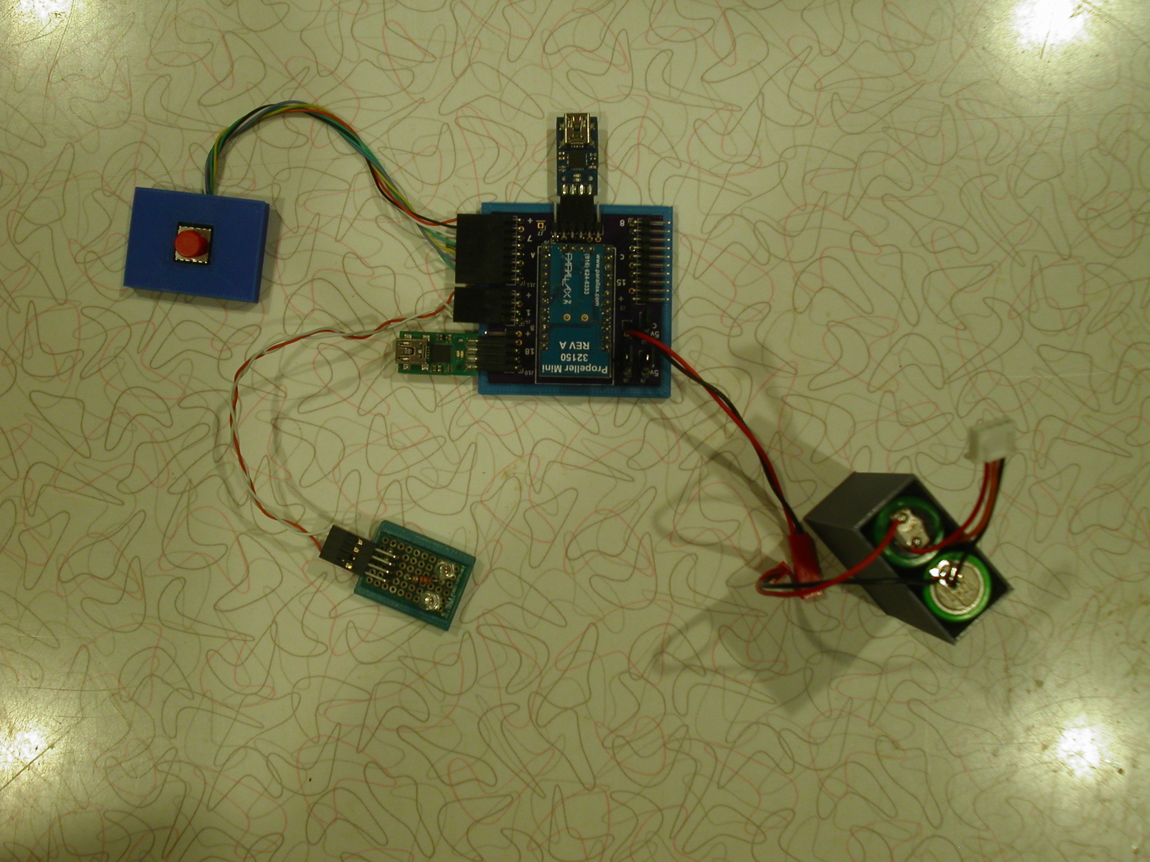
There are two motors: Right-Ascension - East/West - Left/Right, and Declination - North/South - Up/Down.
These motors have two inputs, Direction and ON/OFF. Applying 3 volts to the ON/OFF causes the motor to move and the Direction pin control clockwise or counterclockwise rotation.
The microcontroller can then apply a long or short pulse to these motors so that it either moves fast or slow, Coarse or Fine. One does not even need a microcontroller to make these motors run.
The second piece of the puzzle is the hand controller. It has 4 buttons to control the two motors and a fine and coarse button to control the movement of these motors. The hand controller needs to signal the motor controller what type of movement is needed. How it does this can be done many ways.
The two microcontrollers could be connected by serial to send data from the hand controller to the motor controller.
The motor controller only needs to know three things, what motor to move, what direction to move the motor, and how fast.
To complicate things here there are switches on the motor controller to move the motors without the hand controller.
What we don't know here is how fast the motors move once a signal is applied to the motor. Does it move 1mm per second or does it move 1mm per minute. Since it is used to view something far far away it probably moves very slow but needs to move fast to start with for initial positioning unless there is a freewheeling mode.
Using a square wave to control the motor is not going to work since it generates a stream of pulses causing the motor to run continuously until stopped.
I believe a single pulse is needed here for a specific amount of time to generate the desired movement.
Again, a microcontroller is not even needed for this since buttons could be attached to the motors directly and if you taped the on/off switch the motor would move.
I am done with this project as you claim the propeller is running too fast when the motors are controlled only by the amount of time the on/off pulse is applied to the motors. This has nothing to do with the microcontroller speed. Any microcontroller could be used here.
This could be a fun project to do since it could be connected to a computer that has star charts and be able to move the telescope right to where they are located.
Telescope does not connect to a computer. Motors are steppers that are driven by a MC3479 Controller chip. Controller chip looks for a square wave with a freq. of 6Hz to a freq. of 100Hz. The four switches on the mount chip only represent the guide system which consist of a computer to control the monochrome CCD camera which will be used with a larger scope ( 6 or 7 inch cassagrain scope, instead of a 4 " MacCass telescope. The connectors in the cammera are in fact are Iso-optical chips which will prevent any possible damage to the propeller. (orion EQ2 mount.c(4) is the preferred program I will be using.
You are incorrect. Stepper motors are exactly that. They make one step in the direction indicated. They do not require a frequency to operate.
Again, the motors could be controlled by a switch were every time you pushed the button the motor would move one step in that direction.
The problem still remains. How many clicks does it take to move the mount 1mm?
You are implying that 6 step per second (6hz) moves the motor what?
You are also implying that 100 steps per second (100hz) moves the motor faster the same amount.
These would relate to slow and fast movement of the motors. These exact steps can easily be generated by a microcontroller.
The Square wave function while would produce the pulses necessary would still not be the best way to move the motors.
You need to generate the exact number of pulses to move the motor X otherwise it will move to fast or to slow.
The following code will generate exactly 6 steps in one second.
for (int i=0;i<6;i++)
{
    high(x);
    low(x);
    pause(167);
}
The following code will generate exactly 100 steps in one second:
for (int i=0;i<100;i++)
{
    high(x);
    low(x);
    pause(10);
}
JRoark; I googled MC3479 and it comes up as " Stepper Motor Driver"
Iseries ; The steppers that I am using do not even have a name plate indicating manufacturer or any other info. They were supplied by Orion AstroView EQ.As for the number of steps to move1mm I do not know, I will figure out by adjusting the freq. with software. Circuit has a selector for "full or half step". Setting circles on the mount are graduated in minutes and hours. finally without the use of the MC3479 the draw of the steppers would eat the propeller.
There is no advantage in using Half stepping because it provides half the torque and takes twice as many steps.
Don't forget that you are moving quite a bit of mass and it takes torque to do that.
Unipolar motors can be driven with transistors but a Bipolar motor needs an H-Bridge.
In a Bipolar motor the current can flow in either direction through each coil and that's what an H-Bridge is designed to do.
An L293D can drive up to 600 mA per coil and 'kickback' diodes are built into it.
Also, please put the program filename in the program so that when it's printed out it's easy to tell which program is which version.
And is there a reason why you have .C twice in the filename.
You Define FDrx and FDtx but never use them; instead you use P0 and P1.
What do the Defines Square_Wave and SquareWave do?
Why not move all the extra stuff from Main so the program is easier to read and troubleshoot.
Initialization is only done once so make it a function that Main calls first.
Get Serial Data can be moved to a function.
Get Button Input can be moved to a function.
There is a comment that the Button input overrides Serial so the Camera takes precedence over the handbox.
Currently the program has no way of telling which device is in control.
You are correct about the driver circuit. Now a days we use A4988 to drive stepper motors. If you look at this project, it uses two stepper motors and stepper driver driven by a propeller using a remote control. There is even a video of in action.
The speed of the unit is controlled by the number of steps per second commanded by the remote control.
Maybe we need a test program that pulses these motors at a set value so we can measure the movement and determine what should be used for fast and slow movements.
Genetix: I believe that the MC3479 has h bridges built in along with the timing circuits.
FDserial P0 andP1 are supposed to read P10,P11 Thanks
That's the problem ,I don't know what should be in main, I put the extra defines in to fix errors.
Iseries ; before I deal with Test programs I need to fix the errors in the main program.
I think were getting some now. Degrees can be noted in hours, minutes, and seconds.
So, if we could figure out how many pulses is one minute then that can be used to position the telescope.
If you know a star is located 30 degrees above the horizon and 20 west the program could generate the correct number of pulses move the telescope into position.
I'm not suggesting that you replace any hardware at this point. Just that there are more modern drivers available that are being used with microcontrollers to build precise devices such as 3D printers.
Here is a project that I built that moves a SCARA robot using 3 stepper motors and 3 A4988 stepper drivers connect to a propeller microcontroller running from a Wifi connection to a computer.
1) I looked at video and it's good but can it pickup the entire stack.
2) I loaded and tested the program with my test system. I am using leds instead of motors, and on the motor pins , they are getting maybe 20% of the power. The dir Pins are getting full power.
The L293D is a more primative chip compared to the MC3479.
Your CASE 'A' doesn't check if both motors work at the same time.
I don't understand what your CASE default does because it runs RA East at 8 Hz which doesn't seem right.
I think your Guide Camera input checks should be before the Switch...Case, not in it.
Case A doesn't check but applies anything picked up from FDrx_check, one of four bytes from hand box. I have no outputts from guide control only from the default RmotorPin #17. Will check the hand box tomorrow.
Thanks.
Sorry but I have always found C awkward to use.
I commented what I could understand so you can fix any problems that occur.
Please don't delete the comments and be sure comment any lines that you change.
Feel free to add comments or make any corrections to them.
I don't remember where I saw this but to answer your earlier question about the MC3479.
Motorola MC3749 includes a 16 volt 350 mA H-bridge and control logic with step, direction, and mode inputs to control half-stepping.
In your Post #18 of this thread You sent a couple of test programs to test the serial function And I ran them and I got Printout on the terminal "Pin # 11 High And Pin 11 Low every second Which I assume means the connection is working. Can you check these programs and see what's amiss . I have no data.
Master Telescope Driver(hand box):
Based on the program:
The unit is reading 5 momentary switches:
0 – West
1 – North
2 – East
3 – South
4 – Mode
Each time the mode switch is pressed it goes through 4 different states: Slow, Medium1, Medium2, and Fast then back to Slow.
There are 4 LED’s that indicate these positions:
7 – Low
8 – Medium 1
9 – Medium 2
10- High
When a button is pushed it’s state is saved and then checked for change every 50 milliseconds.
If a direction button is pressed it sets a motor value equal to the mode switch value.
20 – Low
40 – Medium 1
60 – Medium 2
80 – High
East and West set Rmotor and North and South set Dmotor. In addition the direction is captured as 0-No Movement, 1-West, 2-North, 3-East, 4-South, 5-All Stop.
Every 50 milliseconds the switches are read and serial data is sent on pin 6. Far too fast for the print statements at the bottom of the program to work. Also the program is sending binary values to the other side which is not desirable.
Telescope 2A program:
Is opening a serial connection using pin 11 for receive and 10 for transmit at 115200. After that a clock changes is made which will mess with the serial connection. Serial data is clock based and if the clock is changed the data will no longer be aligned.
The clock does not need to be changed and may not work at all with C code.
A check is made to see if there is serial data on pin 11. If there is it is thrown away. It then checks for more serial data and if it is greater than zero it saves it in a 5 character buffer. Since binary data is being sent by the box which has a value of 0 nothing will be recorded.
The hand box is sending: Rmotor, Rdir, Dmotor, Ddir.
Rmotor = 0, 20, 40, 60, 80
Rdir = 0, 1
Dmotor = 0, 20, 40, 60, 80
Ddir = 0, 1
The program is looking for 4 bytes of data otherwise it assumes bad data.
There are also 4 momentary switches that are connected:
4 – West
5 – North
6 – East
7 – South
The default action with no input or buttons is to move the Rmotor at 8 hz continuously. If one of the switches is pushed it will move the motor at 10 hz or 8 hz in that direction continuously. Once a button is released it will go back to moving Rmotor at 8 hz. The square_wave function does not end but because it is used for the other directions it will be overridden and changed to the new values. There will always be a motor moving.
The serial data is not processed once all the data is captured.
This program will not work with the Hand control box. Wrong data.
The hand control box does need to know anything about the motor drive. It should only relay what buttons are pushed. (E, W, N, S) and speed(S,M1,M2,F).
The motor driver should then see those values and drive the motors appropriately.
The hand control box is exactly as you read. the software in Telescope 2A is apparently faulty.
Where is the first clkset being done if not on line 53.
What line throws away first serial data? How do I capture the binary data?
The first program runs the hand control and is designed to send three characters to the motor driver program also attached.
The three characters that are sent are mode and direction. Mode has a value of 0, 1, 2, 3 and direction has a value of W, N, E, and S.
The motor driver program sees these three characters and drives the motors based on them.
I left in the square_wave function and setup an array to hold the different speeds that you may want to use. Don't know how this will work.
For example. If the declination motor moves 1 mm for each pulse then 8 pulses for one second would equal a turn of 8mm. If what you are looking at is in-between that value then you will have no way to center the telescope on that object.
Guide camera code is not included since I have no spec's on what data that program sends to the drive unit.
print( "mode:%c, Direction: %c\n",Buffer[0, Buffer[1]); <-- missing right bracket here
All of this code was loaded and tested on a P1 with buttons and LED's to make sure the code worked. I even connected two serial lines and made sure the data was correct. The only thing that was changed is the pin values as I have a different configuration.


Comments
On last listed programI I got no output on freqout(RmotorPin,50,10) So I changed to SquareWave _set(RmotorPin,0,10) and I get an error: Check source for bad function call or Global Variable Name ' SquareWave_set'.
bbrien,
There is a Square_Wave_Setup function.
https://github.com/parallaxinc/Simple-Libraries/blob/master/Learn/Simple Libraries/Utility/libsimpletools/source/squareWave.c
Do you mind attaching a copy of that Arduino program or point me to the Forum message that has it.
No problem, It is Two " Sketches " Maybe is a problem , can I upload ino files, they are arduino files.
sorry but I have tried everything I can Think of but cannot upload10kbytes of program. Will have to Try zipping the files and it worked.
How do I download files and how do I use them .Can I use the #include.
bbrien,
Spin or C code?
There is a SimpleIDE folder in My Documents that you can create subfolders in unless you want to SimpleIDE to point somewhere else.
You can configure SimpleIDE to look for libraries and programs in specific folders but I think it defaults to the SimpleIDE folder.
Do those Arduino sketches work?
One of the programs communicates using I2C and I don't recall you talking about anything using I2C; the address is 4.
I am not very familiar with the Arduino libraries so I looked them, and I didn't realize that FDSerial is on Parallax Learn under Simple Protocols.
FDSerial stands for Full-Duplex Serial and is formatted like the Spin versions of FullDuplexSerial.
C code.
Yes, the arduino codes did work but not too well.
One of the early problems was I wanted to use the Propeller chip as a slave and I didn't understand the serial that much. Afterwards I switched to multi Props
my next question is where do I insert The square_wave function and the square_wave_setup functions .
Are these a part of the "simpletools,h " libraries
This is some of the most basic functions of any microcontroller that could be used.
There are two motors: Right-Ascension - East/West - Left/Right, and Declination - North/South - Up/Down.
These motors have two inputs, Direction and ON/OFF. Applying 3 volts to the ON/OFF causes the motor to move and the Direction pin control clockwise or counterclockwise rotation.
The microcontroller can then apply a long or short pulse to these motors so that it either moves fast or slow, Coarse or Fine. One does not even need a microcontroller to make these motors run.
The second piece of the puzzle is the hand controller. It has 4 buttons to control the two motors and a fine and coarse button to control the movement of these motors. The hand controller needs to signal the motor controller what type of movement is needed. How it does this can be done many ways.
The two microcontrollers could be connected by serial to send data from the hand controller to the motor controller.
The motor controller only needs to know three things, what motor to move, what direction to move the motor, and how fast.
To complicate things here there are switches on the motor controller to move the motors without the hand controller.
What we don't know here is how fast the motors move once a signal is applied to the motor. Does it move 1mm per second or does it move 1mm per minute. Since it is used to view something far far away it probably moves very slow but needs to move fast to start with for initial positioning unless there is a freewheeling mode.
Using a square wave to control the motor is not going to work since it generates a stream of pulses causing the motor to run continuously until stopped.
I believe a single pulse is needed here for a specific amount of time to generate the desired movement.
Again, a microcontroller is not even needed for this since buttons could be attached to the motors directly and if you taped the on/off switch the motor would move.
I am done with this project as you claim the propeller is running too fast when the motors are controlled only by the amount of time the on/off pulse is applied to the motors. This has nothing to do with the microcontroller speed. Any microcontroller could be used here.
This could be a fun project to do since it could be connected to a computer that has star charts and be able to move the telescope right to where they are located.
Mike
Telescope does not connect to a computer. Motors are steppers that are driven by a MC3479 Controller chip. Controller chip looks for a square wave with a freq. of 6Hz to a freq. of 100Hz. The four switches on the mount chip only represent the guide system which consist of a computer to control the monochrome CCD camera which will be used with a larger scope ( 6 or 7 inch cassagrain scope, instead of a 4 " MacCass telescope. The connectors in the cammera are in fact are Iso-optical chips which will prevent any possible damage to the propeller. (orion EQ2 mount.c(4) is the preferred program I will be using.
I’m confused. The MC3479 is a 3-axis accelerometer, not a stepper controller. Was this a misprint?
You are incorrect. Stepper motors are exactly that. They make one step in the direction indicated. They do not require a frequency to operate.
Again, the motors could be controlled by a switch were every time you pushed the button the motor would move one step in that direction.
The problem still remains. How many clicks does it take to move the mount 1mm?
You are implying that 6 step per second (6hz) moves the motor what?
You are also implying that 100 steps per second (100hz) moves the motor faster the same amount.
These would relate to slow and fast movement of the motors. These exact steps can easily be generated by a microcontroller.
The Square wave function while would produce the pulses necessary would still not be the best way to move the motors.
You need to generate the exact number of pulses to move the motor X otherwise it will move to fast or to slow.
The following code will generate exactly 6 steps in one second.
for (int i=0;i<6;i++) { high(x); low(x); pause(167); }The following code will generate exactly 100 steps in one second:
for (int i=0;i<100;i++) { high(x); low(x); pause(10); }Mike
JRoark; I googled MC3479 and it comes up as " Stepper Motor Driver"
Iseries ; The steppers that I am using do not even have a name plate indicating manufacturer or any other info. They were supplied by Orion AstroView EQ.As for the number of steps to move1mm I do not know, I will figure out by adjusting the freq. with software. Circuit has a selector for "full or half step". Setting circles on the mount are graduated in minutes and hours. finally without the use of the MC3479 the draw of the steppers would eat the propeller.
bbrien,
There is no advantage in using Half stepping because it provides half the torque and takes twice as many steps.
Don't forget that you are moving quite a bit of mass and it takes torque to do that.
Unipolar motors can be driven with transistors but a Bipolar motor needs an H-Bridge.
In a Bipolar motor the current can flow in either direction through each coil and that's what an H-Bridge is designed to do.
An L293D can drive up to 600 mA per coil and 'kickback' diodes are built into it.
Also, please put the program filename in the program so that when it's printed out it's easy to tell which program is which version.
And is there a reason why you have .C twice in the filename.
You Define FDrx and FDtx but never use them; instead you use P0 and P1.
What do the Defines Square_Wave and SquareWave do?
Why not move all the extra stuff from Main so the program is easier to read and troubleshoot.
Initialization is only done once so make it a function that Main calls first.
Get Serial Data can be moved to a function.
Get Button Input can be moved to a function.
There is a comment that the Button input overrides Serial so the Camera takes precedence over the handbox.
Currently the program has no way of telling which device is in control.
Interesting. Two chips with the same number:
https://www.mouser.com/datasheet/2/821/20200827164636363-1900743.pdf
You are correct about the driver circuit. Now a days we use A4988 to drive stepper motors. If you look at this project, it uses two stepper motors and stepper driver driven by a propeller using a remote control. There is even a video of in action.
The speed of the unit is controlled by the number of steps per second commanded by the remote control.
Maybe we need a test program that pulses these motors at a set value so we can measure the movement and determine what should be used for fast and slow movements.
Mike
Genetix: I believe that the MC3479 has h bridges built in along with the timing circuits.
FDserial P0 andP1 are supposed to read P10,P11 Thanks
That's the problem ,I don't know what should be in main, I put the extra defines in to fix errors.
Iseries ; before I deal with Test programs I need to fix the errors in the main program.
I looked at the data sheet for the A4988 , an interesting concept but I don't think I can handle that, it's surface mount teckno.
I think were getting some now. Degrees can be noted in hours, minutes, and seconds.
So, if we could figure out how many pulses is one minute then that can be used to position the telescope.
If you know a star is located 30 degrees above the horizon and 20 west the program could generate the correct number of pulses move the telescope into position.
I'm not suggesting that you replace any hardware at this point. Just that there are more modern drivers available that are being used with microcontrollers to build precise devices such as 3D printers.
Here is a project that I built that moves a SCARA robot using 3 stepper motors and 3 A4988 stepper drivers connect to a propeller microcontroller running from a Wifi connection to a computer.
SCARA robot project
Here is your file corrected with the square wave removed.
One other item maybe that the motors will need to be ramped up otherwise the stepper motors will skip a step due to torque issues.
Mike
1) I looked at video and it's good but can it pickup the entire stack.
2) I loaded and tested the program with my test system. I am using leds instead of motors, and on the motor pins , they are getting maybe 20% of the power. The dir Pins are getting full power.
bbrien,
The L293D is a more primative chip compared to the MC3479.
Your CASE 'A' doesn't check if both motors work at the same time.
I don't understand what your CASE default does because it runs RA East at 8 Hz which doesn't seem right.
I think your Guide Camera input checks should be before the Switch...Case, not in it.
I cleaned up your code and it compiles.
Case A doesn't check but applies anything picked up from FDrx_check, one of four bytes from hand box. I have no outputts from guide control only from the default RmotorPin #17. Will check the hand box tomorrow.
Thanks.
bbrien,
Sorry but I have always found C awkward to use.
I commented what I could understand so you can fix any problems that occur.
Please don't delete the comments and be sure comment any lines that you change.
Feel free to add comments or make any corrections to them.
I don't remember where I saw this but to answer your earlier question about the MC3479.
Motorola MC3749 includes a 16 volt 350 mA H-bridge and control logic with step, direction, and mode inputs to control half-stepping.
In your Post #18 of this thread You sent a couple of test programs to test the serial function And I ran them and I got Printout on the terminal "Pin # 11 High And Pin 11 Low every second Which I assume means the connection is working. Can you check these programs and see what's amiss . I have no data.
From the programs this is what it looks like:
Master Telescope Driver(hand box):
Based on the program:
The unit is reading 5 momentary switches:
0 – West
1 – North
2 – East
3 – South
4 – Mode
Each time the mode switch is pressed it goes through 4 different states: Slow, Medium1, Medium2, and Fast then back to Slow.
There are 4 LED’s that indicate these positions:
7 – Low
8 – Medium 1
9 – Medium 2
10- High
When a button is pushed it’s state is saved and then checked for change every 50 milliseconds.
If a direction button is pressed it sets a motor value equal to the mode switch value.
20 – Low
40 – Medium 1
60 – Medium 2
80 – High
East and West set Rmotor and North and South set Dmotor. In addition the direction is captured as 0-No Movement, 1-West, 2-North, 3-East, 4-South, 5-All Stop.
Every 50 milliseconds the switches are read and serial data is sent on pin 6. Far too fast for the print statements at the bottom of the program to work. Also the program is sending binary values to the other side which is not desirable.
Telescope 2A program:
Is opening a serial connection using pin 11 for receive and 10 for transmit at 115200. After that a clock changes is made which will mess with the serial connection. Serial data is clock based and if the clock is changed the data will no longer be aligned.
The clock does not need to be changed and may not work at all with C code.
A check is made to see if there is serial data on pin 11. If there is it is thrown away. It then checks for more serial data and if it is greater than zero it saves it in a 5 character buffer. Since binary data is being sent by the box which has a value of 0 nothing will be recorded.
The hand box is sending: Rmotor, Rdir, Dmotor, Ddir.
Rmotor = 0, 20, 40, 60, 80
Rdir = 0, 1
Dmotor = 0, 20, 40, 60, 80
Ddir = 0, 1
The program is looking for 4 bytes of data otherwise it assumes bad data.
There are also 4 momentary switches that are connected:
4 – West
5 – North
6 – East
7 – South
The default action with no input or buttons is to move the Rmotor at 8 hz continuously. If one of the switches is pushed it will move the motor at 10 hz or 8 hz in that direction continuously. Once a button is released it will go back to moving Rmotor at 8 hz. The square_wave function does not end but because it is used for the other directions it will be overridden and changed to the new values. There will always be a motor moving.
The serial data is not processed once all the data is captured.
This program will not work with the Hand control box. Wrong data.
The hand control box does need to know anything about the motor drive. It should only relay what buttons are pushed. (E, W, N, S) and speed(S,M1,M2,F).
The motor driver should then see those values and drive the motors appropriately.
Mike
The hand control box is exactly as you read. the software in Telescope 2A is apparently faulty.
Where is the first clkset being done if not on line 53.
What line throws away first serial data? How do I capture the binary data?
Attached are two programs that I tested together.
The first program runs the hand control and is designed to send three characters to the motor driver program also attached.
The three characters that are sent are mode and direction. Mode has a value of 0, 1, 2, 3 and direction has a value of W, N, E, and S.
The motor driver program sees these three characters and drives the motors based on them.
I left in the square_wave function and setup an array to hold the different speeds that you may want to use. Don't know how this will work.
For example. If the declination motor moves 1 mm for each pulse then 8 pulses for one second would equal a turn of 8mm. If what you are looking at is in-between that value then you will have no way to center the telescope on that object.
Guide camera code is not included since I have no spec's on what data that program sends to the drive unit.
Mike
nice picture. this one taken with the 10 inch SMT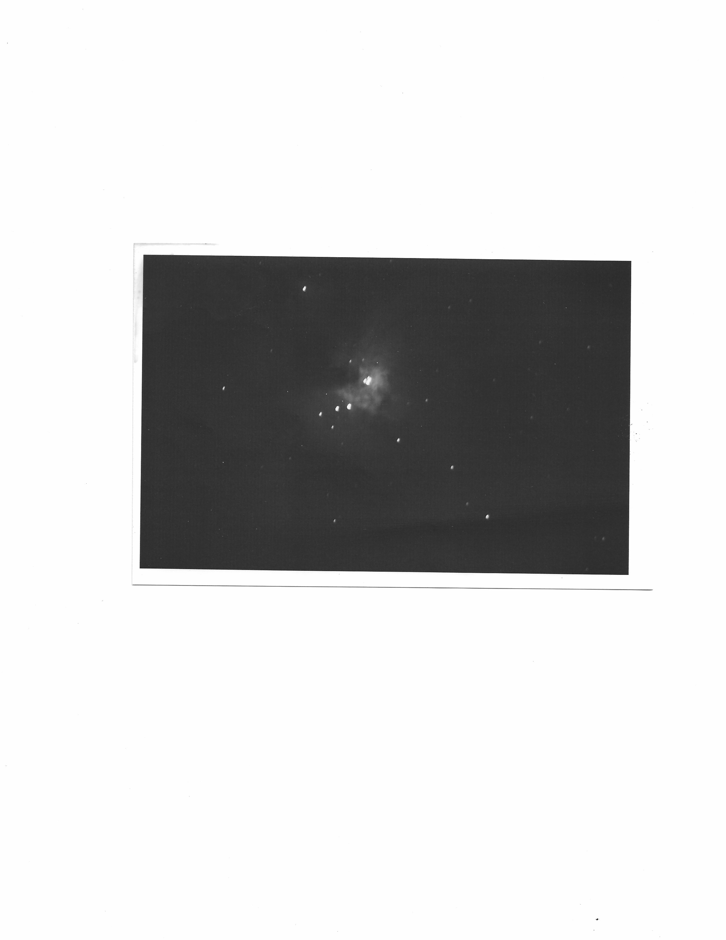
I just tried to compile your last post for mount chip and came up with errors concerning several lines. check the error rescue in this post.
bbrien,
iseries did not define the Mode Pin.
Perhaps you should of used copy and past as there are syntax errors here.
and also this
All of this code was loaded and tested on a P1 with buttons and LED's to make sure the code worked. I even connected two serial lines and made sure the data was correct. The only thing that was changed is the pin values as I have a different configuration.
Mike