I don't know how to copy and paste . sometimes it fails so I retyped and this time only one error and I found the mistake and corrected it and now almost every thing works. the only failure is in the hand box ,; no Led lights, they don't turn on.
Hi mike, on the hand control program there is still no indicator lights indicating the speed we're set at. Also I need the continuation when the button is depressed.
If there are no light for mode values then you don't have your LEDs connected to pins 7, 8, 9, and 10. Don't have your circuit drawing so have no idea.
There is no auto repeat function for the buttons. Use the low, medium and fast mode switch for small to coarse movements.
Sw5 is connected to pin 4 which on the mini outputs 3.3v.I must have lost the connect. between D1 and D2, bad mouse. I am trying to get used to my new mouse. All 5 switches send a high to their pins.
@bbrien said:
Sw5 is connected to pin 4 which on the mini outputs 3.3v.I must have lost the connect. between D1 and D2, bad mouse. I am trying to get used to my new mouse. All 5 switches send a high to their pins.
The point that I’m aiming for is this: unless SW5 has a resistor to ground, that switch isnt doing anything at all. When that switch is open, P4 floats (or it is high if in fact your statement about P4 being driven high is correct). And when SW5 is closed it drives P4 high… which means P4 never changes from that high state because P4 never transitions to low.
In Post 57 you sent two programs. The serial works good but the motors or lights should stray on until the switch(s) are released. I am going to try to merge the serial components of your last programs with the working parts of my programs which will take some time, wish me luck .Wish I understood this stuff better.
Have you run test programs to verify that your switches and LEDs work, or have you verified that your PCB artwork is correct and checked the actual connections with a DMM?
Yes They change mode and send direction bits with several different programs I have used but the serial doesn't work right but for some reason I have lost most of my programs.
Did any of the Forum programs mostly work?
If so which ones and in which thread are they since you have several.
Also how would you characterize the different skew rates?
Low, Medium, High, Ultra?
I ask because like the directions the program can send just one letter including O for Off.
Also have the Serial transit and receive pins changed, and what things works correctly and what things don't work?
Most of the "forum" programs didn't work well the ones that even work are: Telescope2A. c and
Telescope Driver A. c but I cannot get the serial to work. Back to looking at spin on dh9 and
Telescope Test GEN fixed 2_b.
As I said before the serial connection( interface) is working as the Master and Slave test programs that you sent did work but all they did is print the data coming into the chip from serial. nothing gets done to the output by the program.
I have setup a test jig based on what I know about the two units.
Here is a schematic of what I setup which may not be the same pins that you used:
I used a 5 button switch to control the mode and direction of the motors shown in the following video: Telescope Test Setup Video
I use a state define to control if the switches are active high or active low. My switches are active low so I set state to 0
The attached zip file has the two program used in the video with only the pin definitions changed back to what you had them set to. They are not what I used.
Serial between the two units only requires two wires. Tx pin hand control to Rx pin on telescope controller and ground. Both units must share the same ground or serial will not work.
If I recall correctly, Spin can bit-bang serial at 9600 baud such as in BS2_Functions.Spin.
That's true, but it's unbuffered, so just like the BASIC Stamp, you have to be sitting on a receive function to ensure you don't miss it.
You don't always have to add the space of an entire object for a couple of methods. I used these in my Spin1 PixyCam driver. The variable bittix is the system frequency divided by the baud rate (up to 38400).
pri tx_byte(b) | t

'' Transmit byte b, true mode on txpin

  b := (b | $FF00) << 2                                         ' add start and stop bits

  t := cnt                                                      ' sync with system timer
  repeat 10                                                     ' send start, 8 bits, 1 stop (8n1)
    waitcnt(t += bittix)                                        ' hold 1 bit period
    outa[txpin] := b >>= 1                                      ' output bit (from LSB end)


pri rx_byte : b | t

'' Receive byte b, true mode on rxpin
'' -- returns one byte
'' -- blocking code!

  waitpne(rxmask, rxmask, 0)                                    ' wait for start bit
  t := cnt + (bittix >> 1)                                      ' sync + half bit
  repeat 8
    waitcnt(t += bittix)                                        ' hold 1 bit period
    b := (b | ina[rxpin]) -> 1                                  ' get the bit (from LSB end)
  waitpeq(rxmask, rxmask, 0)                                    ' wait for stop bit

  b >>= 24                                                      ' align to low byte
To Iseries ; What's it mean " parameters are initialized" in reference to int Rspeed[] = { 10, 20, 30, 80};
To Jon ; I will check out the exerpt when I return to Spin.


Comments
I don't know how to copy and paste . sometimes it fails so I retyped and this time only one error and I found the mistake and corrected it and now almost every thing works. the only failure is in the hand box ,; no Led lights, they don't turn on.
tested the programs but another problem arises, i need the program to run when switches are depressed and not when released.
Let me get this straight. Your switches are at ground level and when you push them they go to 3 volts, active high instead of low.
To fix that you need to change "i == 0" to "i != 0" in each program.
Mike
Hi mike, on the hand control program there is still no indicator lights indicating the speed we're set at. Also I need the continuation when the button is depressed.
If there are no light for mode values then you don't have your LEDs connected to pins 7, 8, 9, and 10. Don't have your circuit drawing so have no idea.
There is no auto repeat function for the buttons. Use the low, medium and fast mode switch for small to coarse movements.
Mike
Here is the schematic for hand controller.
Schematic file does not work. Missing outside items that you used. Pins are not identified.
You might be able to export out to the clipboard and past it into Paintbrush or some other graphics program and save it as PNG file.
Mike
Hope this works for you. What does "set mode leds(0)" do?
Looks like you're missing a connection on LEDs 2, 3, and 4. The only LED that should work is 1.
Mike
It seems that SW5 needs a pull-down resistor to ground because as it currently stands it can only go from +V to floating.
ADDIT: D2, D3, D4 each need their own resistor if there is a possibility more than one could be turned on at once.
Sw5 is connected to pin 4 which on the mini outputs 3.3v.I must have lost the connect. between D1 and D2, bad mouse. I am trying to get used to my new mouse. All 5 switches send a high to their pins.
The point that I’m aiming for is this: unless SW5 has a resistor to ground, that switch isnt doing anything at all. When that switch is open, P4 floats (or it is high if in fact your statement about P4 being driven high is correct). And when SW5 is closed it drives P4 high… which means P4 never changes from that high state because P4 never transitions to low.
My mistake, the board has 5 10k resistors connecting pins 0-4 to ground. when I drew up the first boards I forgot to include the pull-down resistors.
Still does not indicate why they are not turning on for each of the different modes. They should be working then.
Mike
Maybe they are installed backwards?
Nope; they work when using orion EQ2 driver.
In Post 57 you sent two programs. The serial works good but the motors or lights should stray on until the switch(s) are released. I am going to try to merge the serial components of your last programs with the working parts of my programs which will take some time, wish me luck .Wish I understood this stuff better.
bbrien,
Have you run test programs to verify that your switches and LEDs work, or have you verified that your PCB artwork is correct and checked the actual connections with a DMM?
Yes They change mode and send direction bits with several different programs I have used but the serial doesn't work right but for some reason I have lost most of my programs.
bbrien,
Did any of the Forum programs mostly work?
If so which ones and in which thread are they since you have several.
Also how would you characterize the different skew rates?
Low, Medium, High, Ultra?
I ask because like the directions the program can send just one letter including O for Off.
Also have the Serial transit and receive pins changed, and what things works correctly and what things don't work?
Most of the "forum" programs didn't work well the ones that even work are: Telescope2A. c and
Telescope Driver A. c but I cannot get the serial to work. Back to looking at spin on dh9 and
Telescope Test GEN fixed 2_b.
Serial has to work since it is used to program the units.
Are you using prop chips without a crystal or something. That would be the only reason that serial does not work.
Mike
nope ,5 meg hz.
As I said before the serial connection( interface) is working as the Master and Slave test programs that you sent did work but all they did is print the data coming into the chip from serial. nothing gets done to the output by the program.
I have two programs which worked with serial but are written in spin.
bbrien,
So what is the problem with those Spin programs then?
The spin programs wouldn't work with the steppers. If I had one DC and one stepper it worked but when I tried to set up with two steppers it failed.
I have setup a test jig based on what I know about the two units.
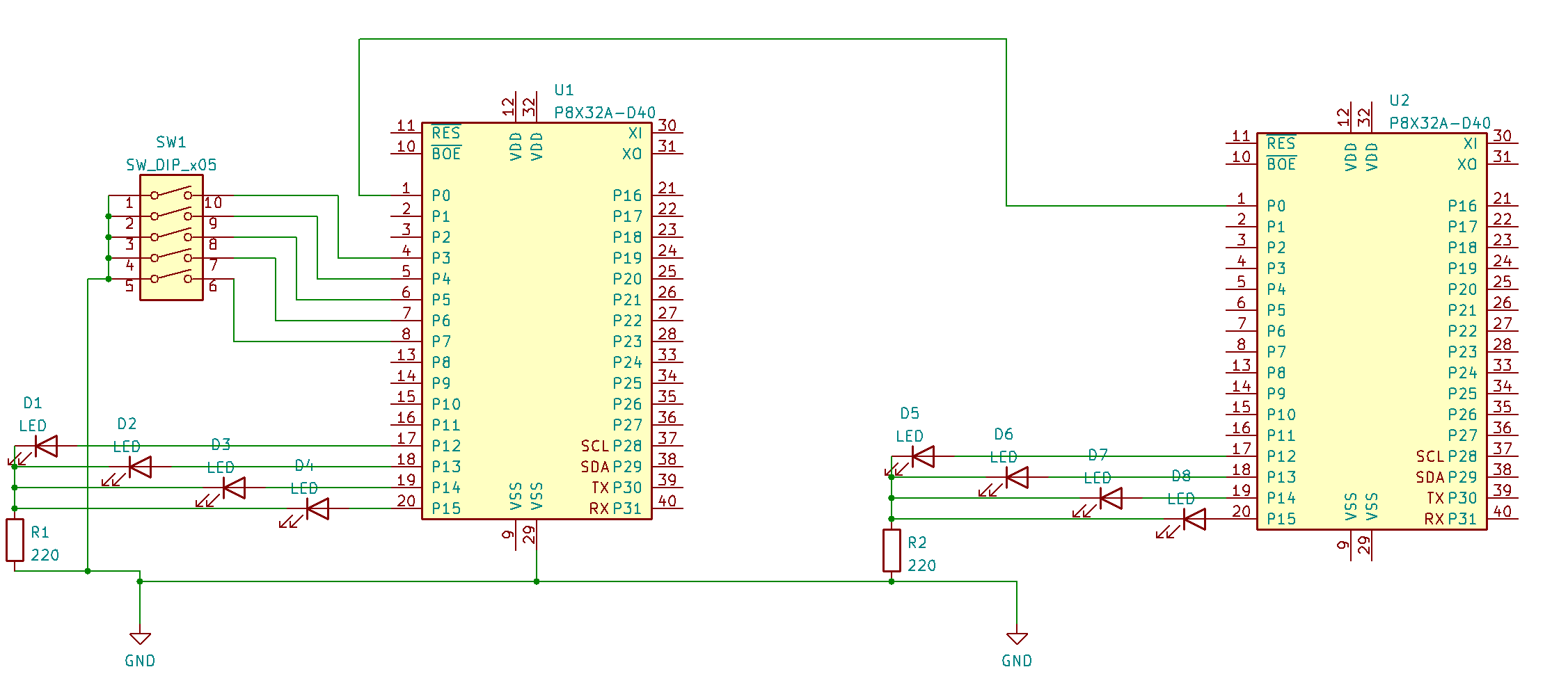
Here is a schematic of what I setup which may not be the same pins that you used:
I used a 5 button switch to control the mode and direction of the motors shown in the following video:
Telescope Test Setup Video
I use a state define to control if the switches are active high or active low. My switches are active low so I set state to 0
The attached zip file has the two program used in the video with only the pin definitions changed back to what you had them set to. They are not what I used.
Serial between the two units only requires two wires. Tx pin hand control to Rx pin on telescope controller and ground. Both units must share the same ground or serial will not work.
Mike
bbrien,
As iseries points out, the serial between the handbox and mount is only Half-Duplex or one direction at a time.
If I recall correctly, Spin can bit-bang serial at 9600 baud such as in BS2_Functions.Spin.
That's true, but it's unbuffered, so just like the BASIC Stamp, you have to be sitting on a receive function to ensure you don't miss it.
You don't always have to add the space of an entire object for a couple of methods. I used these in my Spin1 PixyCam driver. The variable bittix is the system frequency divided by the baud rate (up to 38400).
pri tx_byte(b) | t '' Transmit byte b, true mode on txpin b := (b | $FF00) << 2 ' add start and stop bits t := cnt ' sync with system timer repeat 10 ' send start, 8 bits, 1 stop (8n1) waitcnt(t += bittix) ' hold 1 bit period outa[txpin] := b >>= 1 ' output bit (from LSB end) pri rx_byte : b | t '' Receive byte b, true mode on rxpin '' -- returns one byte '' -- blocking code! waitpne(rxmask, rxmask, 0) ' wait for start bit t := cnt + (bittix >> 1) ' sync + half bit repeat 8 waitcnt(t += bittix) ' hold 1 bit period b := (b | ina[rxpin]) -> 1 ' get the bit (from LSB end) waitpeq(rxmask, rxmask, 0) ' wait for stop bit b >>= 24 ' align to low byteTo Iseries ; What's it mean " parameters are initialized" in reference to int Rspeed[] = { 10, 20, 30, 80};
To Jon ; I will check out the exerpt when I return to Spin.