Does the 1.8 V regulator output still shows exactly the same burst of spikes as in post #294, just before current drainage lowers the 3.3 V line, forcing PG to fall, and causing P2 to reset?
Perhaps the internal bias sourcing for the PLL/VCO isn't able to keep "breathing", loosing control, and letting Sysclk frequency to scale-up, worsening the power consumption even more.
@Yanomani said:
Does the 1.8 V regulator output still shows exactly the same burst of spikes as in post #294, just before current drainage lowers the 3.3 V line, forcing PG to fall, and causing P2 to reset?
Perhaps the internal bias sourcing for the PLL/VCO isn't able to keep "breathing", loosing control, and letting Sysclk frequency to scale-up, worsening the power consumption even more.
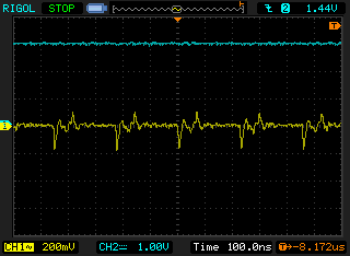
Not completely sure what you asking but here are the 1.8V switching spikes that I see close up under heavy load when I've boosted the input to 3.6V.
Yes well I would say it looks around the same. Spikes are probably about -200mV down and then 60mV overshoot in both cases. My latest operating picture is just this voltage rail zoomed in but this low end scope is not high resolution. I think without a voltage boost the input voltage just falls and the regulator can't cope with the lowered voltage and doesn't really get to startup properly before it encounters the PG condition once its output falls outside the 8% window.
EDIT: actually it is probably tripping the UVLO threshold of 2.2V at VIN. That causes PG to go low too.
... it was my bad phrasing (sorry!), inducing to a gross reversal of cause, and effect, when I stated "just before current drainage lowers the 3.3 V line": in fact, is the lowering of 3.3 V due to current consumption that causes 1.8 V instabilities.
Thanks rogloh, for taking your time doing a detailed explanation.
No worries. I think I've put this issue to bed now and understand why the P2 was shutting down. It's not the P2 overheating or my regulator doing strange things, but can be explained by simple resistive losses in my test setup and likely won't be an issue with my board. I've also proven that this regulator can supply the P2 with sufficient current at 1.8V.
Given I've felt how hot the P2 can get under full load I'm just glad I added a fan option to my carrier board and will likely put it to good use. Hopefully I'll not come anywhere near this load in practice and probably will only clock the P2 at 200-240MHz or so and will not have all COGs streaming and fully using CORDIC etc.
IIRC, your carrier board can also be equiped with a temperature-sensing capable RTC, so monitoring this parameter would enable turning the fan on/off, as needed?
Yeah I have multiple ways to measure temp on my boards.
1) on P2ME2 I have a footprint for an optional small temp sensor that outputs an analog voltage - this is fitted very close to the P2.
2) on VOYAGER carrier
- one i2c based temp sensor close to P2ME2 heat source and warmed airflow
- 2nd i2c based temp sensor on bottom of board far away from hot regulators and P2ME2 etc (for reference/enclosure temp)
- ATMega AVR microcontroller has a temp sensor too IIRC.
- possibly the MCP79401 RTC? EDIT: no it doesn't include temp sensing.
I also have a FET to PWM the 5V fan which is under micro control.
Certainly a great demo of how much the power consumption depends on the program code. This is a modern trait though. It happens due to the large number of parallel data paths possible when the architecture supports it. In the early days, CPUs relied heavily on centralised databuses - which limited the amount of parallel activity.
I had added a INA219 sensor to the carrier board which would have been great to measure P2 current/power etc... but it's no longer in P2 supply path unless I drive my 5V reg harder to power everything as I originally planned to before I found out how hot its inductor got. That's why my P2ME2 board can be supplied by up to 17V now to essentially shed load from my carrier board's 5V regulator. I can still make use of this sensor to measure 5V peripheral power including an audio amp, a USB host supply and LCD panel, which already probably need around 1.5A from memory.
I can only wonder how much more 5V current it would have needed with the P2 running evanh's test code!
The AP3445 regulator is sold as a 2 Amp part. But I see the partnered inductor is 3.8 Amp rated and I can't see anything that specifically limits current in the regulator itself. It seems we've got enough over-engineering in the revB Eval Board to handle the 3 Amps.
Right. So thermal shutdown is the likely outcome of going too far. I note from the graphs in the AP3445 datasheet that 80 mOhm is a more typical R(on) for the P channel.
I did strike an unexplained variation in power use. Each time I ran those tests I got a slightly different current draw. Each time was steady but with a small change from prior run. Only just noticed it when retesting earlier configs to verify some of the results I already had.
The more times I tested one config the more variations of current draw I ended up with. Admittedly, it's only a couple of milliamps each time. But still the changes were steady during each run.
@rogloh said:
I had added a INA219 sensor to the carrier board which would have been great to measure P2 current/power etc... but it's no longer in P2 supply path unless I drive my 5V reg harder to power everything as I originally planned to before I found out how hot its inductor got.
Actually I lied here, it turns out there is a sense resistor placed that lets me tap into the total 12V current flowing into the 5V reg and what will now also feed the P2ME2 board VIN, so I will know the majority of the system current and power consumption. It just won't measure the VOYAGER's 3.3V rail which is for the supervising AVR and RTC and i2c temp sensors, this is fine as they are already very low power anyway so won't contribute much overall especially when sleeping.
@evanh said:
Which suggests its a fake register. I remember it was only added on request. The FIFO was already working long before that register existed.
Huh, just tested it in the middle of hubRAM and it still does the same. GETPTR doesn't wrap around with the block wrapping. It only increments. Looks like that may have been a known quirk at design. I don't see it mentioned in the two main google docs though.
The first mention I was able to find to the non-wrapping-around behavior of GETPTR dates back to ~6 years ago (eh eh, note the title of the thread were it was stated by Chip...):
Tonight I soldered up the remaining TI 5-17V switcher that generates the 3.3V for the 1.8V regulator and VCCIO.
Despite the somewhat cruddy hand soldering it seems to work and now generates about 3.2V on that rail to power the board. I have also loaded some code on the P2 with it operating from that supply.
Looks like I need to clean this board more. Without this magnification it looked reasonably clean but my eyes are not the best.
Update: one problem with that TI part is that it seems to be in shortage now. Probably due to being suited to automotive uses. I need to find an alternative pin compatible device or another source if I want more parts. I think I only have one more of these parts.
Correction: looks like I have zero TI regulator parts. I must have dropped the other one left on the floor and now can't see it! Damn. Will need to look for it tomorrow in the light.
Found some ChemTools circuit board flux cleaner and applied it. Here's some better shots with it cleaned up a bit more.
The missing parts around IC3 are for an optional i2c hot swap circuit which I might add down the track if I need it. C46 is a bypass cap for an optional oscillator (not needed as I'm using the crystal here), and U4 is an optional analog temperature sensor which I still have to order.
Oh, I was thinking for diagnostics, not deployment. I've got mine plugged into one of my multimeters. Have to fold the fine Ni-chrome wires a few times to give the banana-plugs something to screw down on.
I don't think the Prop2 ADCs are anywhere near good enough, not directly anyway. It's exactly where 100x gain is needed but at GND/GIO voltage, not VIO/2. And it seems 100x input select isn't so great either, the noise floor rises quite a lot compared to 10x gain. So, an instrumentation amplifier is needed as minimum. May as well use an ADC designed for thermocouples. I2C or SPI versions are easy to get.
I think the easiest way to incorporate some kind of temperature measurement is to replace the (10k?) CS Flash pullup resistor with a high value thermistor. You can combine that with the P2's internal 15k pulldown resistor and measure the analog voltage at P61 to get temperature.
It'll need a calibration run of course, but depending on value chosen you can either program that analog voltage operating point to be inside the 'adc zoom windows' at the temperatures of interest, or always well above 1.65v if you don't want to risk the flash chip becoming active
@rogloh said:
Update: one problem with that TI part is that it seems to be in shortage now. Probably due to being suited to automotive uses. I need to find an alternative pin compatible device or another source if I want more parts. I think I only have one more of these parts.
Correction: looks like I have zero TI regulator parts. I must have dropped the other one left on the floor and now can't see it! Damn. Will need to look for it tomorrow in the light.
Maybe that larger SOT23 package is less preferred these days ?
I see TI have parts in SOT-563 and
even SOT-583 , with PG : TPS563211 NEW ACTIVE 4.2-V to 18-V, 3-A, synchronous buck converter with 1% accuracy, PG/SS and PFM/forced-PWM in SOT583
A bit better Vmin and a bit better RDS on the FETs
Of course, they are even harder to see on the floor


Comments
Does the 1.8 V regulator output still shows exactly the same burst of spikes as in post #294, just before current drainage lowers the 3.3 V line, forcing PG to fall, and causing P2 to reset?
Perhaps the internal bias sourcing for the PLL/VCO isn't able to keep "breathing", loosing control, and letting Sysclk frequency to scale-up, worsening the power consumption even more.
Not completely sure what you asking but here are the 1.8V switching spikes that I see close up under heavy load when I've boosted the input to 3.6V.
I was looking at that specific portion of 1.8 V regulator output, as posted earlier:
Yes well I would say it looks around the same. Spikes are probably about -200mV down and then 60mV overshoot in both cases. My latest operating picture is just this voltage rail zoomed in but this low end scope is not high resolution. I think without a voltage boost the input voltage just falls and the regulator can't cope with the lowered voltage and doesn't really get to startup properly before it encounters the PG condition once its output falls outside the 8% window.
EDIT: actually it is probably tripping the UVLO threshold of 2.2V at VIN. That causes PG to go low too.
... it was my bad phrasing (sorry!), inducing to a gross reversal of cause, and effect, when I stated "just before current drainage lowers the 3.3 V line": in fact, is the lowering of 3.3 V due to current consumption that causes 1.8 V instabilities.
Thanks rogloh, for taking your time doing a detailed explanation.
No worries. I think I've put this issue to bed now and understand why the P2 was shutting down. It's not the P2 overheating or my regulator doing strange things, but can be explained by simple resistive losses in my test setup and likely won't be an issue with my board. I've also proven that this regulator can supply the P2 with sufficient current at 1.8V.
Given I've felt how hot the P2 can get under full load I'm just glad I added a fan option to my carrier board and will likely put it to good use. Hopefully I'll not come anywhere near this load in practice and probably will only clock the P2 at 200-240MHz or so and will not have all COGs streaming and fully using CORDIC etc.
IIRC, your carrier board can also be equiped with a temperature-sensing capable RTC, so monitoring this parameter would enable turning the fan on/off, as needed?
Yeah I have multiple ways to measure temp on my boards.
1) on P2ME2 I have a footprint for an optional small temp sensor that outputs an analog voltage - this is fitted very close to the P2.
2) on VOYAGER carrier
- one i2c based temp sensor close to P2ME2 heat source and warmed airflow
- 2nd i2c based temp sensor on bottom of board far away from hot regulators and P2ME2 etc (for reference/enclosure temp)
- ATMega AVR microcontroller has a temp sensor too IIRC.
- possibly the MCP79401 RTC? EDIT: no it doesn't include temp sensing.
I also have a FET to PWM the 5V fan which is under micro control.
Certainly a great demo of how much the power consumption depends on the program code. This is a modern trait though. It happens due to the large number of parallel data paths possible when the architecture supports it. In the early days, CPUs relied heavily on centralised databuses - which limited the amount of parallel activity.
Yes this a handy test evanh. Thanks for providing it.
Yes, I did tought it has that capability, but it does not.
I had added a INA219 sensor to the carrier board which would have been great to measure P2 current/power etc... but it's no longer in P2 supply path unless I drive my 5V reg harder to power everything as I originally planned to before I found out how hot its inductor got. That's why my P2ME2 board can be supplied by up to 17V now to essentially shed load from my carrier board's 5V regulator. I can still make use of this sensor to measure 5V peripheral power including an audio amp, a USB host supply and LCD panel, which already probably need around 1.5A from memory.
I can only wonder how much more 5V current it would have needed with the P2 running evanh's test code!
I estimate, at 360 MHz, that my code needs 3 Amps from the 1.8 regulator.
P2-Hot (lite)
The AP3445 regulator is sold as a 2 Amp part. But I see the partnered inductor is 3.8 Amp rated and I can't see anything that specifically limits current in the regulator itself. It seems we've got enough over-engineering in the revB Eval Board to handle the 3 Amps.
RDS(on) might be the limit for that AP3445. 3A through 100milliohms in the FET is already close to 1W of heat loss.
Right. So thermal shutdown is the likely outcome of going too far. I note from the graphs in the AP3445 datasheet that 80 mOhm is a more typical R(on) for the P channel.
I did strike an unexplained variation in power use. Each time I ran those tests I got a slightly different current draw. Each time was steady but with a small change from prior run. Only just noticed it when retesting earlier configs to verify some of the results I already had.
The more times I tested one config the more variations of current draw I ended up with. Admittedly, it's only a couple of milliamps each time. But still the changes were steady during each run.
Ah, I know, it'll depend on what the random preset in PA is for the QMUL.
Actually I lied here, it turns out there is a sense resistor placed that lets me tap into the total 12V current flowing into the 5V reg and what will now also feed the P2ME2 board VIN, so I will know the majority of the system current and power consumption. It just won't measure the VOYAGER's 3.3V rail which is for the supervising AVR and RTC and i2c temp sensors, this is fine as they are already very low power anyway so won't contribute much overall especially when sleeping.
A bit late with this, but does GETPTR wrap around to zero at the end of hub RAM ($000FFFFF followed by $00000000) ?
Yes it does, I called that rollover (which makes it a 20-bit register), but kind of irrelevant when it doesn't follow a block wrap.
EDIT: I suppose I should've been saying block modulo rather than block wrap.
Tonight I soldered up the remaining TI 5-17V switcher that generates the 3.3V for the 1.8V regulator and VCCIO.
Despite the somewhat cruddy hand soldering it seems to work and now generates about 3.2V on that rail to power the board. I have also loaded some code on the P2 with it operating from that supply.
Looks like I need to clean this board more. Without this magnification it looked reasonably clean but my eyes are not the best.
Update: one problem with that TI part is that it seems to be in shortage now. Probably due to being suited to automotive uses. I need to find an alternative pin compatible device or another source if I want more parts. I think I only have one more of these parts.
Correction: looks like I have zero TI regulator parts. I must have dropped the other one left on the floor and now can't see it! Damn. Will need to look for it tomorrow in the light.
Found some ChemTools circuit board flux cleaner and applied it. Here's some better shots with it cleaned up a bit more.
The missing parts around IC3 are for an optional i2c hot swap circuit which I might add down the track if I need it. C46 is a bypass cap for an optional oscillator (not needed as I'm using the crystal here), and U4 is an optional analog temperature sensor which I still have to order.
Begging for a thermocouple to be sunk into the centre solder blob!
Yeah that would be nice. What circuitry would be needed for the P2 to be able to use one? Can it be read directly?
Oh, I was thinking for diagnostics, not deployment. I've got mine plugged into one of my multimeters. Have to fold the fine Ni-chrome wires a few times to give the banana-plugs something to screw down on.
I don't think the Prop2 ADCs are anywhere near good enough, not directly anyway. It's exactly where 100x gain is needed but at GND/GIO voltage, not VIO/2. And it seems 100x input select isn't so great either, the noise floor rises quite a lot compared to 10x gain. So, an instrumentation amplifier is needed as minimum. May as well use an ADC designed for thermocouples. I2C or SPI versions are easy to get.
https://forums.parallax.com/discussion/173508/direct-thermocouple-measurement
I think the easiest way to incorporate some kind of temperature measurement is to replace the (10k?) CS Flash pullup resistor with a high value thermistor. You can combine that with the P2's internal 15k pulldown resistor and measure the analog voltage at P61 to get temperature.
It'll need a calibration run of course, but depending on value chosen you can either program that analog voltage operating point to be inside the 'adc zoom windows' at the temperatures of interest, or always well above 1.65v if you don't want to risk the flash chip becoming active
Maybe that larger SOT23 package is less preferred these days ?
I see TI have parts in SOT-563 and
even SOT-583 , with PG : TPS563211 NEW ACTIVE 4.2-V to 18-V, 3-A, synchronous buck converter with 1% accuracy, PG/SS and PFM/forced-PWM in SOT583
A bit better Vmin and a bit better RDS on the FETs
Of course, they are even harder to see on the floor")