@rogloh said:
I am trying to pinpoint it down to being PG or PropPlug by removing the PropPlug from the reset source after download but every time I yank the PropPlug out it generates a reset spike! I
You could remove (shift) the cap in the prop plug reset and just manually reset things for testing.
@rogloh said:
... About 100ms after the program runs the CORDIC+streamer pin loading test with the 8 COGs I see a 1.2ms active low reset pulse and it shuts down.
I'm going to setup my scope to trigger on this PG pulse and monitor the 1.8V rail at the output cap to see if I find anything there.
Data says PG works on Over/Under VOUT, and UVLO and Temperature, and has 20us leading and 100us recovery, so 1.2ms needs to include some other timing effect ?
If it is not droop, I wonder if noise outside the valid window can accumulate enough to trigger it ?
@jmg said:
Data says PG works on Over/Under VOUT, and UVLO and Temperature, and has 20us leading and 100us recovery, so 1.2ms needs to include some other timing effect ?
There is two switchers chained together in Roger's board. The reset time probably combines both.
@jmg said:
You could remove (shift) the cap in the prop plug reset and just manually reset things for testing.
I could but for now it's easier the way I have it. I just wired 3 pins of the PropPlug to my board and power on/off my supply.
@rogloh said:
... About 100ms after the program runs the CORDIC+streamer pin loading test with the 8 COGs I see a 1.2ms active low reset pulse and it shuts down.
I'm going to setup my scope to trigger on this PG pulse and monitor the 1.8V rail at the output cap to see if I find anything there.
Data says PG works on Over/Under VOUT, and UVLO and Temperature, and has 20us leading and 100us recovery, so 1.2ms needs to include some other timing effect ?
If it is not droop, I wonder if noise outside the valid window can accumulate enough to trigger it ?
I'm not sure. Now I've instrumented it and am probing, the problem has gone away again.
I'll need to AC couple my scope to catch a 8% voltage fall or rise from 1.8V. It's not a lot more than the rail's current noise floor.
@jmg said:
Data says PG works on Over/Under VOUT, and UVLO and Temperature, and has 20us leading and 100us recovery, so 1.2ms needs to include some other timing effect ?
There is two switchers chained together in Roger's board. The reset time probably combines both.
Not using the first switcher yet, that's not on my board. Feeding 3.3V directly into the 1.8V regulator. Although the 3.3V supply is from an SMPS power supply, maybe SMPS only as a pre-regulator (not sure). Wavecom PS3005-D model. https://www.wavecom.com.au/03_product_images/815/PS-3005D.jpg
I used some heavy wires from the bench to the board, 0.75mm2 I think, so as to limit the droop there. But I also could raise it to 5.5 Volts to help even more. I note you're tied to VIO. You could get away raising that to 3.6 Volts easy enough.
Gonna try again later. I can't make this fail so easily now (Heisenbug due to observation?) and after about 30s of really heavy load the P2 gets so hot I'm too scared to keep running the test and fry my P2 and so I shut it down. Also I only see 700-750mA now instead of that 800-900mA peak I reached earlier, even though it is the same program running - weird.
Ah, one of the things I did was to setup a smartpin toggling at sysclock/1000. That way I could verify what the PLL was achieving:
        dirl    #MPIN
        wrpin   #%01_00110_0, #MPIN     'smartpin NCO frequency mode
        wxpin   #500, #MPIN         'sysclock/1000 to monitor PLL frequency as die heats
        wypin   ##$8000_0000, #MPIN
PS: If the Prop2 throttles then Cogs may crash too.
PPS: That code was in the launcher cog. Whereas the DIRH instruction, to enable the smartpin, was placed in the test cogs.
man, using a soldering iron at those sizes is ridiculous. Even trying to de-solder a single resistor has me smothering everything else. Then it vanished. Not a clue where the damn thing went.
Turns out my AUX supply doesn't work at all. I'd removed the USB switch after it went short and any attempt to use that supply just turns the whole board off. It was the revA Eval Board that I'd wired for AUX USB after it'd failed in a similar manner. It had used larger parts and the pins of the regulator allowed for an easy jumper across the pads.
What I must have done to get high current on the revB Eval Board was back-feed the 5 volts from an Accessory header.
@evanh said:
Which suggests its a fake register. I remember it was only added on request. The FIFO was already working long before that register existed.
Huh, just tested it in the middle of hubRAM and it still does the same. GETPTR doesn't wrap around with the block wrapping. It only increments. Looks like that may have been a known quirk at design. I don't see it mentioned in the two main google docs though.
The first mention I was able to find to the non-wrapping-around behavior of GETPTR dates back to ~6 years ago (eh eh, note the title of the thread were it was stated by Chip...):
Lol, Chip ended up making a scope mode too. I only just learnt it is a specific streamer mode just the other day. I had thought the smartpin "scope" mode was intended as input to Goertzel mode but Goertzel has its own bitstream filter.
My old tests peaked at around 3.45 Watts for VDD. But that was using an inline current meter and I struggled to get everything plugged in cleanly so there is some doubt on its accuracy.
Tonight I tested by measuring just the 5 volt benchtop supply to ensure better accuracy. At the same time I've also changed the test software a number of times since too, so can't be sure which of the two changes is the biggest factor.
At any rate, tonight's test wasn't hugely up on the old tests. At 360 MHz, I've clocked in 3.88 Watts measured from 5V supply.
Also, measuring the current at the ACC_5V LDO_VIN jumper I see 8.5 mA while clocked at 360 MHz. A mere 45 mW. Idling at RCFAST this is 3.64 mA. So, less than I was even expecting, VIO is insignificant. EDIT: Ah, and that 8.5 mA includes driving P56 50% duty into the LED.
Had some more time today to look at this load issue again.
Left the stress test running for longer with a scope set to trigger on falling edge of reset (driven by PG). Added a fan so I can run for a while without it getting too hot. Still can't seem to get it to trigger, currently drawing ~750mA at 3.3V. Noise is 33mV RMS on 3.3V and 1.8V rails. I can also see narrow -100mV glitches on the 1.8V at the ~4MHz switcher frequency but these would be filtered out by the regulator anyway. It seems very stable now.
Now that I've added active cooling I'd like to somehow add more P2 load to stress that regulator more and see if I can make it drop PG low.
Nope, the only driven pin is P56 for monitoring sysclock/1000. VIO power use is only a few milliwatt - not under test. Most of LDO_VIN current will be 8 x LDO quiescent + P56 LED current.
The source code needs a clean up. Had to debug some mess-ups just because of the clutter. Here it is anyway:
EDIT: Updated the source with correct 360 MHz data point.
BTW: I've hit 5 Watts at 360 MHz. Oops, it maybe higher. Just noticed it drops away from 360 MHz as I cross 30 C. That definitely shows a large thermal gradient!
Yep, threw in a couple freezer packs to hold the heatsink down and got me 5.45 Watts!
@evanh said:
Nope, the only driven pin is P56 for monitoring sysclock/1000. VIO power use is only a few milliwatt - not under test. Most of LDO_VIN current will be 8 x LDO quiescent + P56 LED current.
The source code needs a clean up. Had to debug some mess-ups just because of the clutter. Here it is anyway:
EDIT: Updated the source with correct 360 MHz data point.
Cheers @evanh.
I will try this out. I've also just found a bug in my stress code that was preventing the streamer transfers from being enabled. With that fixed I see 1.2A @ 3.3V in my own test or ~ 4W now. I can also make it fail to startup.
@evanh said:
Nope, the only driven pin is P56 for monitoring sysclock/1000. VIO power use is only a few milliwatt - not under test. Most of LDO_VIN current will be 8 x LDO quiescent + P56 LED current.
Ah, there is more than what I was thinking. I've got the smartpins all toggling their respective outputs (drive disabled). Even though they aren't driving the pins they do still draw a little current from VIO for internal pad-ring activity.
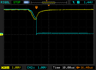
Looks like inrush current issues at startup causing the P2 to be shutdown under heavy load. Blue is PG signal output by regulator, yellow is 1.8V AC coupled supply voltage.
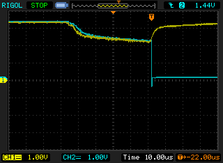
And here is the 3.3V input supply voltage to the regulator in yellow.
@evanh said:
Hehe, 2 Volts ain't doing the job. Supply cabling from the benchtop too weak maybe?
Yeah 2V is just not enough.
I will try to add a bulk cap to the 3.3V supply pins and change/shorten the power leads if needed to see if it helps. Ideally a low ESR cap but might not have one of those handy.
Added a 100uF cap (non low-ESR one) to the 3.3V pin parallel to the supply connector, but it only delayed the inevitable.
I guess this means I have a resistive drop that loses voltage under load.
That worked! (With the cap). It started up and pulled 1.7A at 3.6V using your program evanh. Over 6W!
Not all of this goes into the P2. I measured 3V on my 3.3V input pin so I am losing 0.6V in the cabling.


Comments
You could remove (shift) the cap in the prop plug reset and just manually reset things for testing.
Data says PG works on Over/Under VOUT, and UVLO and Temperature, and has 20us leading and 100us recovery, so 1.2ms needs to include some other timing effect ?
If it is not droop, I wonder if noise outside the valid window can accumulate enough to trigger it ?
PC motherboard designers certainly have their work cut out for them in getting 300 Watts into the CPU at 1.1 Volts.
There is two switchers chained together in Roger's board. The reset time probably combines both.
I could but for now it's easier the way I have it. I just wired 3 pins of the PropPlug to my board and power on/off my supply.
I'm not sure. Now I've instrumented it and am probing, the problem has gone away again.
I'll need to AC couple my scope to catch a 8% voltage fall or rise from 1.8V. It's not a lot more than the rail's current noise floor.
Yes some careful design there.
Not using the first switcher yet, that's not on my board. Feeding 3.3V directly into the 1.8V regulator. Although the 3.3V supply is from an SMPS power supply, maybe SMPS only as a pre-regulator (not sure). Wavecom PS3005-D model.
https://www.wavecom.com.au/03_product_images/815/PS-3005D.jpg
I used some heavy wires from the bench to the board, 0.75mm2 I think, so as to limit the droop there. But I also could raise it to 5.5 Volts to help even more. I note you're tied to VIO. You could get away raising that to 3.6 Volts easy enough.
Gonna try again later. I can't make this fail so easily now (Heisenbug due to observation?) and after about 30s of really heavy load the P2 gets so hot I'm too scared to keep running the test and fry my P2 and so I shut it down. Also I only see 700-750mA now instead of that 800-900mA peak I reached earlier, even though it is the same program running - weird.
Ah, one of the things I did was to setup a smartpin toggling at sysclock/1000. That way I could verify what the PLL was achieving:
dirl #MPIN wrpin #%01_00110_0, #MPIN 'smartpin NCO frequency mode wxpin #500, #MPIN 'sysclock/1000 to monitor PLL frequency as die heats wypin ##$8000_0000, #MPINPS: If the Prop2 throttles then Cogs may crash too.
PPS: That code was in the launcher cog. Whereas the DIRH instruction, to enable the smartpin, was placed in the test cogs.
man, using a soldering iron at those sizes is ridiculous. Even trying to de-solder a single resistor has me smothering everything else. Then it vanished. Not a clue where the damn thing went.
Turns out my AUX supply doesn't work at all. I'd removed the USB switch after it went short and any attempt to use that supply just turns the whole board off. It was the revA Eval Board that I'd wired for AUX USB after it'd failed in a similar manner. It had used larger parts and the pins of the regulator allowed for an easy jumper across the pads.
What I must have done to get high current on the revB Eval Board was back-feed the 5 volts from an Accessory header.
The first mention I was able to find to the non-wrapping-around behavior of GETPTR dates back to ~6 years ago (eh eh, note the title of the thread were it was stated by Chip...):
https://forums.parallax.com/discussion/comment/1355690/#Comment_1355690
Thanks Yanomani.
Lol, Chip ended up making a scope mode too. I only just learnt it is a specific streamer mode just the other day. I had thought the smartpin "scope" mode was intended as input to Goertzel mode but Goertzel has its own bitstream filter.
You're always welcome!
The way it got implemented, GETPTR is kind of a smart rabbit, ever a step ahead of all tracking sighthounds.
My old tests peaked at around 3.45 Watts for VDD. But that was using an inline current meter and I struggled to get everything plugged in cleanly so there is some doubt on its accuracy.
Tonight I tested by measuring just the 5 volt benchtop supply to ensure better accuracy. At the same time I've also changed the test software a number of times since too, so can't be sure which of the two changes is the biggest factor.
At any rate, tonight's test wasn't hugely up on the old tests. At 360 MHz, I've clocked in 3.88 Watts measured from 5V supply.
Also, measuring the current at the ACC_5V LDO_VIN jumper I see 8.5 mA while clocked at 360 MHz. A mere 45 mW. Idling at RCFAST this is 3.64 mA. So, less than I was even expecting, VIO is insignificant. EDIT: Ah, and that 8.5 mA includes driving P56 50% duty into the LED.
PLL self-limiting drops below 360 MHz when the heatsink rises above 40 ℃.
PS: There'll be some thermal gradient given the power input to get there.
I'm touching 4 Watts at just 250 MHz now. Still trying more ...
Had some more time today to look at this load issue again.
Left the stress test running for longer with a scope set to trigger on falling edge of reset (driven by PG). Added a fan so I can run for a while without it getting too hot. Still can't seem to get it to trigger, currently drawing ~750mA at 3.3V. Noise is 33mV RMS on 3.3V and 1.8V rails. I can also see narrow -100mV glitches on the 1.8V at the ~4MHz switcher frequency but these would be filtered out by the regulator anyway. It seems very stable now.
Now that I've added active cooling I'd like to somehow add more P2 load to stress that regulator more and see if I can make it drop PG low.
Can you post your binary stress test image evanh? I could only get about 3W drawn from the supply at its peak but now it is about 2.5W.
Also I have a flash chip onboard that I can't disable, hopefully your test won't short its output pin.
Nope, the only driven pin is P56 for monitoring sysclock/1000. VIO power use is only a few milliwatt - not under test. Most of LDO_VIN current will be 8 x LDO quiescent + P56 LED current.
The source code needs a clean up. Had to debug some mess-ups just because of the clutter. Here it is anyway:
EDIT: Updated the source with correct 360 MHz data point.
BTW: I've hit 5 Watts at 360 MHz. Oops, it maybe higher. Just noticed it drops away from 360 MHz as I cross 30 C. That definitely shows a large thermal gradient!
Yep, threw in a couple freezer packs to hold the heatsink down and got me 5.45 Watts!
Cheers @evanh.
I will try this out. I've also just found a bug in my stress code that was preventing the streamer transfers from being enabled. With that fixed I see 1.2A @ 3.3V in my own test or ~ 4W now. I can also make it fail to startup.
Ah, there is more than what I was thinking. I've got the smartpins all toggling their respective outputs (drive disabled). Even though they aren't driving the pins they do still draw a little current from VIO for internal pad-ring activity.
Adds 3 mA at 25 MHz and 16 mA at 300 MHz.
Looks like inrush current issues at startup causing the P2 to be shutdown under heavy load. Blue is PG signal output by regulator, yellow is 1.8V AC coupled supply voltage.
And here is the 3.3V input supply voltage to the regulator in yellow.
Hehe, 2 Volts ain't doing the job. Supply cabling from the benchtop too weak maybe?
Yeah 2V is just not enough.
I will try to add a bulk cap to the 3.3V supply pins and change/shorten the power leads if needed to see if it helps. Ideally a low ESR cap but might not have one of those handy.
It doesn't look like storage issue to me. It looks resistive losses.
Added a 100uF cap (non low-ESR one) to the 3.3V pin parallel to the supply connector, but it only delayed the inevitable.
I guess this means I have a resistive drop that loses voltage under load.
Boost the set volts to 3.6 too.
That worked! (With the cap). It started up and pulled 1.7A at 3.6V using your program evanh. Over 6W!
Not all of this goes into the P2. I measured 3V on my 3.3V input pin so I am losing 0.6V in the cabling.
Hehe, that's a whole Watt in the cable!