

Direct thermocouple measurement
 ManAtWork
Posts: 2,367
ManAtWork
Posts: 2,367
Inspired by this and this older threads I made an experiment to test if it's possible to read the voltage from a thermocouple directly (meaning without pre-amplifier or external ADC) with the P2. Of course, it's not really "directly" because an external analogue multiplexer is required.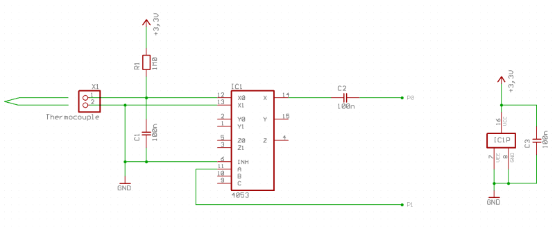
The MUX switches the ADC input between both wires of the thermocouple resulting in a square wave AC signal which can then be captured by the P2 ADC in 100X gain mode. As already discussed in the high-gain-thread those modes are not suitable for DC signals.
'' ThermoADC.spin2
'' Test program for AC coupled thermocouple measurement
'' with analogue multiplexer

' To cancel out noise from both 50Hz and 60Hz mains interference
' the ADC input is filtered with a 10Hz averaging filter.
' 100ms = 18e6 cycles = 8000 * 2250
' 2250 samples with 8000 clock SINC2 mode (~13bits)
' sample frequency = 22.5 kHz
' Mux switch frequency 22.5kHz / 50 = 450 Hz
' first two samples after Mux switch are dropped
' 23 of 25 samples per halve wave are added to the odd/even bin

' resolution and scaling:
' 100X mode has 5V / 100 = 50mV full scale = 8000 LSBs
' 1 LSB = 6.25µV (single sample)
' Thermocouple type K sensitivity = ~40µV/°K
' total samples per average value = 23 * 45 = 1035
' scaling factor = 1 / 1035 * 6.25 / 40 = 1/6624 °K/LSB

' to-do:
' * add VIO/GIO calibration
' * implement table or polynomial linearization
' * add cold junction compensation

CON
  _xtlfreq = 25_000_000
  _clkfreq = 180_000_000
  sampleTime = 8000 ' clocks per sample
  sampleMux  = 25   ' samples per MUX state (inner loop)
  sampleAvg  = 2250 / 50 ' MUX cycles per average (outer loop)
  sampleDrop = 2    ' how many samples to drop after state change
  '_BAUD       = 230400 ' serial debug port

' Pins
  pinAdc = 0 ' ADC input
  pinMux = 2 ' MUX output to 4053

  modeAdc = P_ADC + P_ADC_100X
  modeSinc2 = %01_1101 ' SINC2 filtering 8192 clocks

OBJ
  com : "jm_serial.spin2"

VAR
  long  bin0
  long  bin1
  long  acc
  long buf0[100]
  long buf1[100]

PUB main | x, i
  com.start (_BAUD)
  InitAdc
  repeat ' endless loop
    bin0:= 0
    bin1:= 0
    repeat sampleAvg' filter outer loop
      pinl (pinMux)
      i:= 0
      repeat sampleDrop
        x:= GetSample
        'buf0[i++]:= x
      repeat sampleMux - sampleDrop ' filter inner loop
        x:= GetSample
        buf0[i++]:= x
        bin0+= x
      pinh (pinMux)
      i:= 0
      repeat sampleDrop
        x:= GetSample
        'buf1[i++]:= x
      repeat sampleMux - sampleDrop ' filter inner loop
        x:= GetSample
        buf1[i++]:= x
        bin1+= x
    com.str (string ("avg="))
    com.dec ((bin0 - bin1) * 10 / 6624) ' output 0.1°K units
    com.tx (32)
    repeat i from 0 to 3
      com.fhex (buf0[i], 4)
      com.tx (32)
    'com.tx (10)
    repeat i from 0 to 3
      com.fhex (buf1[i], 4)
      com.tx (32)
    com.tx (10)

PRI InitAdc
  pinstart (pinAdc, modeAdc, modeSinc2, sampleTime)
  asm
    setse1 #1<<6 + pinAdc
  endasm

PRI GetSample : s | x
  asm
    waitse1
  endasm
  x:= rdpin (pinAdc)
  x-= acc
  acc+= x
  return (x>>12) & $3FFF ' right adjust to 14 bits
My first test code does not support linearization, cold junction compensation nor auto-calibration. But it demonstrates at least that it's possible. If I touch the tip with my fingers it reads 5..6° above ambient and it I put the soldering iron on it it reads ~230° above ambient. It might be not enough for a high precision thermometer but with some calibration it should be at least suitable to control a tin melting pot where 1..2°K tolerance is acceptable.
Charge injection of the analogue switch is not a problem. If that was the case the first samples after a MUX state change should show a remarkable RC decay curve beacuse the switching charges C1 and C2 which are then discharged by the thermocouple and the input resistance of the ADC. This is not the case, instead, noise is the limiting factor.
I intentionally tested with a "good old" 4053 IC because if it works with that one it works with any other type. Another reason was that I've found one in the depths of my heap of spare parts which nicely fitted to my breadboard.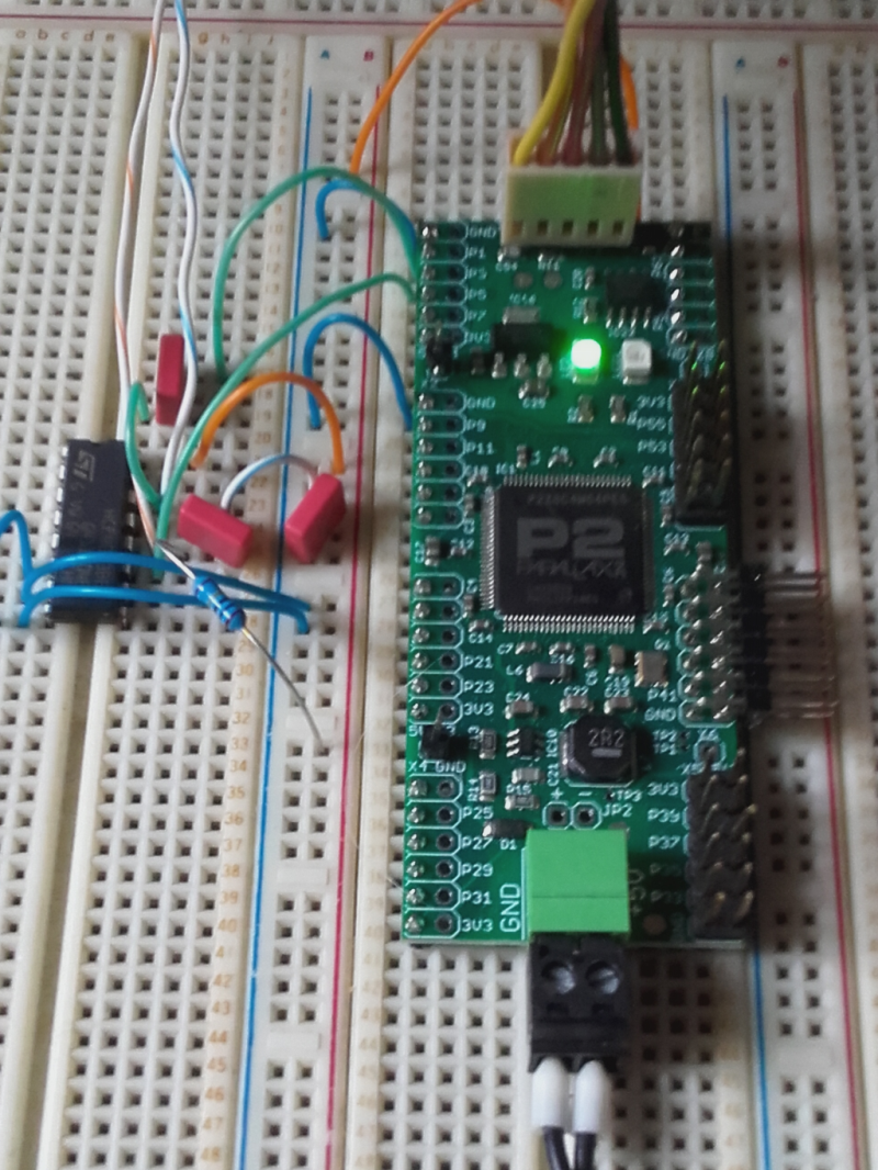
Comments
Some thoughts about calibration:
DC offsets can be ignored since the signal is AC coupled. VIO/GIO calibration in 1X gain mode should at least remove the biggest part of the gain error. Resistor values and current sources inside the P2 have a part-to-part variation and drift over temperature. Those errors can be compensated with auto-calibration so that only the resistor-to-resistor ratio error (1X to 100X gain ratio) remains that should be quite low.
If that's still not good enough the 1:2 multiplexer could be replaced by a 1:4 one. This would allow external calibration with a precision voltage source and would also remove the error of the 3.3V regulator.
If the total gain error can be reduced to 1% that would mean less than +/-2.5K tolerance for a soldering pot which is acceptable.
That could work, but I just find it easier to use an external amp, with CJC etc. like a AD8497 or LTCxx
Huh, I suspect revB parts, since they have a "pinA" and "pinB" low-level input select for each ADC modulator, could do that without needing the 4053 IC.
Would need two C2 caps though ... Or instead maybe rely on insulated wiring and use the wire-break biasing resistors to centre the thermocouple at 1.65 volts.
The possible spanner in that idea is that each input source, to the ADC, has its own series resistor. Which will introduce extra offsets at 100x gain.
EDIT: Hmm, it's a big spanner.
The 4053 can give you a 3:1 MUX in 2 stages.
I think the calibrate is done at the same gain, to avoid that issue, so you create a precision millivolt reference.
The 3v3 regulator is part of the feedback so drift there cannot be avoided, so you make that a better 3v3.
With 0.1% low drift resistors and a 0.1%~0.5% regulator, quite good absolute gain calibrate should be possible.
eg a MCP1501T-33E/CHY is 3v3 20mA 0.1% in SOT23-6, tho with a modest 50ppm/°C
JMG,
You've mixed up my idea of using only the internals. The spanner is only in reference to my idea of relying only on internal gain and resistors of the revB prop2.
Yes, relying on the ratio of internal resistor values is somewhat speculative. And we need a precision voltage reference, anyway, because the 3.3V supply is not precise enough. So this schematic should be better:
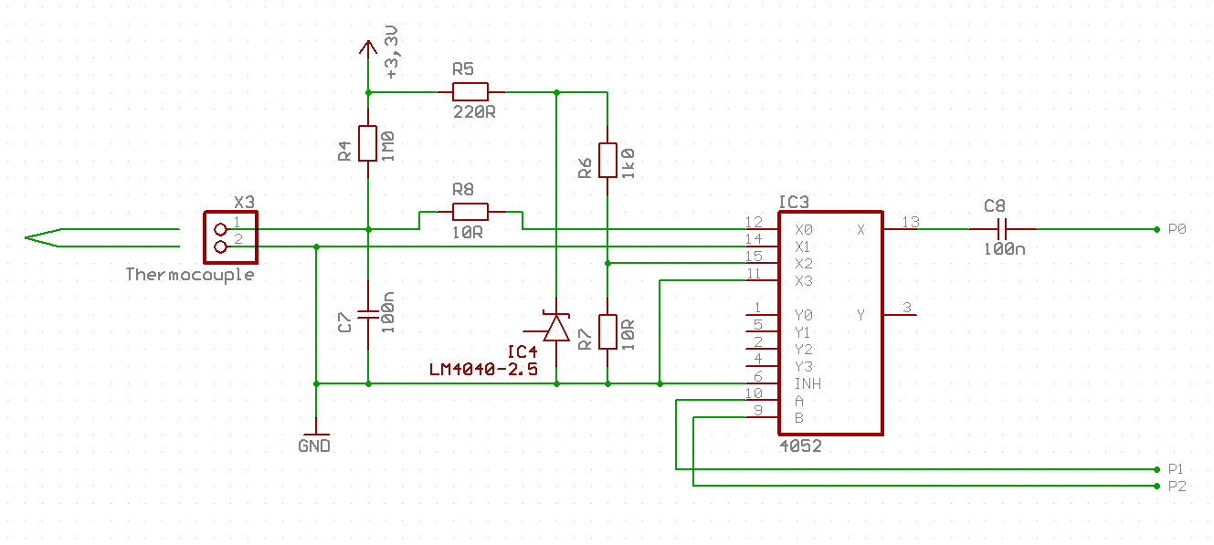
R5 delivers 3.6mA total which is divided into 2.5mA into the voltage divider and 1.1mA to the shunt voltage reference. R8 is to match the source resistance of the thermocouple to that of the voltage devider. R4 is a weak pullup for the case that the thermocouple wire should break which results in an ADC overflow.
The multiplexer switches P1/A with a high frequency to get an AC signal. P2/B is switched with a low frequency to alternate between themperature measurement and constant reference (25mV or ~600°C for a type K thermocouple). If the on resistances of the 4 switch paths are matched all gain and offset errors should be cancelled out.
I know, when considering cost and development time this approach doesn't make much sense. An external precision ADC would only cost ~$1 more which would be lost in the noise for industrial applications. But this might be a good demonstration of what is possible with the internal ADCs of the propeller with only very little external componens. We'll find out if it works...
My experiments today displayed a temperature of around 95°C when I held the tip of the thermocouple into boiling water. The reference voltage at pin 15 was 24.63mV instead of the ideal 24.75mV = 2.5V/101, so the reading should actually be higher instead of lower. I've used kelvin connections for pin pairs 12-14 and 15-11 so the breadboard setup couldn't be blamed for the bad results.
I think this is good enough for a basic demonstration for educational projects but unfortunatelly not for a real industrial control application.
Here is the test code. Output is in 0.1°C units.
Actual boiling point depents on air pressure and may be lower then 100 C. At altitude 2000m its 93
sampleDrop = 2: Was that experimentally arrived at?
We are at 500m above sea level so the boiling point should be something slightly above 98°C.
Of course, the on resistance of the analogue multiplexer and the coupling capacitor cause some damping of the signal. But this should affect the reference signal in the same way as the thermocouple signal.
After all, it's not all that bad. The MAX31855 also has +/-2°C tolerance (but over the whole range of -250 to +1400°C).
Try this on line 75:
adc:= ((adc+64) SAR 7) * 24752 / ((ref+64) >> 7)Oh, the
referr, the250temperature should really be the cold-junction temperature. Not having a live measurement for that will introduce error.Thanks for the hint. My spin2 port of the TMP102 driver still had a bug so I did the cold junction compensation in my head. The thermometer said 26°C room temperature, one degree above my hard-coded 25° so I added 1° to the actual output of 94° and said 95° in my post.
My Spin skills are non-existent but reading the
compensatemethod it doesn't look entirely coherent. There isreturn ...andresult := ...followed by areturn, andr := ...(without areturn) at the end of the method. I thought an explicitreturnwas needed. And it looks likeris the assigned return variable, doesresultstill work?Also,
>|and|<don't exist in Spin2. I'm guessing you're relying on Flexspin's backwards compatibility features.Assigning the return variable or an explicit return work both. result probably doesn't in the original propeller tool. I used FlexSpin and simply edited the spin1 source until no more error messages occured.")
In Spin1 there is a predefined return variable called RESULT one can use so assigning a value to RESULT is the same as writing RETURN value. A explicit RETURN RESULT is not needed.
In Spin2 one must explicit define return values, there can be more then one return value.
Enjoy!
Mike
And the case where it assigns the returning
rbut has noreturnat the end? Does that exit the method or not?it returns r at the end with or without return statement. To return in between you need to write return r where you need it.
Mike