I’ve been spending a lot of time on the P2 forum and learning C programming using FlexSpin. That’s a great tool and works well. To learn C I am spending time on the Parallax Tutorials which has a very nice C tutorial written for the P1. It’s been fairly easy to translate the lessons over to the P2 so far. The P2 C setup has a lot of add-ons for math so last night was spent writing some simple programs to enter an angle and output the sin value. I was getting lots of errors before I realized the sin() function used rads instead of angles for input. After that it got much easier. Today I want to start converting my Inverse Kinematics formulas from the P1 program over and see if I can get them running also.
C hasn’t been too bad to learn so far but I’m still in the very basic stages of it, I’m sure it will get more interesting soon! As it is I tend to make a lot of stupid mistakes that keep things from compiling...
Still looking for a serial communications object that can handle several separate input/outputs. I’ll have to look at the P1 versions of these objects to see if I can convert one over to the P2 if one doesn’t show up by the time I need it. The other thing that needs setting up is the XBee radio, will need to get a interface board since none of the P2 boards have that incorporated and create a P2 object to interface. Lots of stuff to do still but it’s all fun.
Bob
PS. I sold my big metal lathe which required dismantling the hexapod as it was in the way for getting the lathe out of the basement. Finally got the robot back together again (lots more space for testing the legs now!) so hopefully I’ll be able to start testing with the P2 board before too long.
Fun times learning new P2 language, specifically C for the P2.
My first adventure was converting the existing Inverse Kinematics (IK) formulas into something that would compile under FlexSpin. First off I had to remind myself about how I went about coming up with the original equations. That required some digging and finding the PDF (see attached) with my calculations.
Next step was entering the equations and lots of work getting the syntax right!
I got everything up and running faster than I expected, the C math library was much easier to use than floating point on the P1! The test code outputs to a windows terminal window with the calculation results. I'd like to output to the Propeller Serial Terminal (PST) window if I can figure out how to get FlexSpin to change its default output.
Now I'm working on getting the robot RGB troubleshooting LEDs to work under P2. The P1 object for the LPD8806 is a combination of Spin and pasm and I'm pretty rusty on assembly. I've been trying out a Spin only bit-banged approach but it isn't working quite right yet. The LPD8806 LED Driver chip appears to be unique and there isn't much out there, even the datasheet doesn't show the timing requirements for the chip. The only other driver I found on-line was written in C for an Arduino so not much help there. I'm about ready to give it up and switch over to the WS2812B RGB modules that Parallax sells. There are several P2 drivers already developed for it.
Bob
I think if you leave off the '-t' parameter in the command line P2load will not start the build in terminal and you can use the Propeller Terminal as you did with the P1.
I got a lot of help from the folks on the P2 forum and especially JonnyMac in coming up with a driver for the LPD8806 RGB controller. The driver works great so it's time to move on to the next item on the list.
Next is getting a multi-port serial device set up. The P1 master code uses 2, 4 port serial objects. There are 8 serial lines being used; 1 for master to leg controllers (one way comms only), 6 receive lines from each leg controller to the master (one way comms also), and 2 way comms via the PropPlug (mainly for troubleshooting).
I started fiddling with a simple serial driver, jm_serial.spin2, unfortunately I managed to break it and now it isn't responding. JonnyMac recommended that I look into his FullDuplexSerial code as he set it up better for handling multiple ports. So its off to reviewing more code and seeing what it might take to allow it to handle more lines. I have seen that the P2 Smart Pins capabilities are pretty nice and can greatly reduce the amount of setup code needed for tasks like this. Study time again!
Nothing else to update on, still haven't quit on this project!
Bob:
Back on page 19, you shared that you had to rewrite the encoder code for the HH12 encoders. Are you willing to share that P1 code? I am about to start putting together my bot arm and I would like to use that for positioning. btw do you happen to know if the HH12 is still available?
Jim
Bob:
Back on page 19, you shared that you had to rewrite the encoder code for the HH12 encoders. Are you willing to share that P1 code? I am about to start putting together my bot arm and I would like to use that for positioning. btw do you happen to know if the HH12 is still available?
Jim
Not a problem, I’ll dig that code out and will post it here, haven’t looked at that code since I got it working. I don’t know if the guy I bought the encoders from still makes them, I’ll look up the contact info (he is in Germany) and pass that on to you.
Just a update on robot status. I'm working towards creating a multi-port serial object for the P2 created based on the JonnyMac jm_fullduplexserial.spin2 object. Jon writes some very well documented code which helps a lot for figuring things out. Since no one has written a serial object with multiple ports, I'm teaching myself P2pasm so I can try my own hand at making one. I haven't done assembly for any processor in many years so its been a slow undertaking given the scarcity of documentation at this point (Parallax has lots of stuff is in the pipeline but I want to get a jump on it now). I have read the available documents several times and reviewed a lot of other folks assembly in P2 (Whew, lots of words to figure out and finding examples of the new P2 specific assembly commands takes a lot of searching). With the help of people on the P2 forum, its finally starting to make sense to me. Now whether or not it makes enough sense that I can write my own serial driver is another matter altogether! The hope is that I can write a 8 port buffered serial driver that uses one cog.
Anyway I have been attending the weekly Parallax Zoom meetings covering the various aspects of the P2. These sessions have been a lot of fun. I've learned a lot just from attending these sessions and have been having some fun playing with P2 spin coding. I really like the P2 Edge board and I got the mini breakout board for it along with the Jon McPhalen Edge Module Breadboard from Parallax. I think the P2 Edge will be make for a nice robot master computer and I want to mount the mini breakout board on the robot computer deck. It should make wiring to the 6 P1 boards fairly easy to do using jumpers.
The Boston Dynamics Atlas robot, I would only guess that you put sensors on a real dancer record the moves, then program the robot with the dance moves.
It’s been a while since my last update here but I have been active on the Parallax P2 forum instead.
I’m continuing work on a version of a multi-port serial object, lots of studying P2 pasm and other’s code. After several fits and starts I finished up my first version of the code, unfortunately it doesn’t work properly so now I’m using Pnut and debugging to figure out where I’m going wrong.
In the meantime Cluso99 created his own multi-port serial object that seems to work pretty well. I’m still continuing on working on my version as a good excuse to get better at P2 pasm and I’ve designed the interface to the code to be similar to the P1 multi-port serial object I have been using on the master computer. That will make converting my existing master P1 code over to the P2 somewhat easier.
Once I get the serial object running I am going to re-visit coding the inverse kinematics engine using some of the built-in P2 functions instead of running the code in C under FlexProp. I think long term that will make the code easier to maintain instead of having Spin, C, and Pasm all mixed together.
No additional changes to the mechanical features on the robot at this point. After selling my big metal lathe I had to re-assemble the robot and now I have a larger testing area in the basement.
I completed work on the P2 multi-port serial object so moved on to the next item on the to-do list.
I couldn't find my P2 C code I wrote for doing Inverse Kinematics so I re-did the code in FlexProp C and got it working fairly quickly. I really want to do all the coding in Spin2 and PASM so I started looking into creating a math/trig library that I can use. To maximize speed of calculations everything is being designed using integer math. The P2 made sin and cos easy to put together (with some help from others on the forum). arcsin and arccos were a bit more difficult but got help from Eric Smith and that's good to go. Currently working on arctan and atan2. Based on the hints from a couple of forum members, in theory these should be the easiest to do but my brain has gone into a math freeze zone and I am not getting the expected results. Once atan and atan2 are figured out I should have all the objects I need to install the P2 Edge in the robot and start programming it directly again.
I removed the old P1 Activity Board that was acting as the master from the robot. It will be replaced with a P2 Edge board mounted on the mini-breakout board. The holes on the board are much smaller than the holes for on the Activity board, it appears to use metric 2.6 sized screws so I need to get out of the house and down to the hardware store to get the board mounted.
The integer based trig Spin2 library is done and working, so cross that item off the to-do list. It includes sin, cos, tan, arctan, arcsin, arccosine, atan2.
Next item was re-writing the Inverse Kinematics formulas using Spin2. As I was able to compare outputs with the ‘C’ based IK code it was fairly easy to identify issues quickly and fix them. The IK code re-write from P1 to P2 didn’t take as long as I anticipated but it is done and working. I really should do some tests to see how much speed improvement there is using the P2 vs P1 but I believe the speed increase will be significant. The P2 can run at 300Mhz vs 80Mhz and integer math is always going to be faster than floating point math. Even the new version of Spin is faster.
Next item on the list was updating the programming computer in the basement with the new versions of the Propellor Tool (v2.5.2). That turned out to be a tougher problem than anticipated. Turns out that computer runs Windows 7 (64 bit home premium) and has been divorced from any internet/wireless connection for many years. I use flash drives to move needed code to it, turns out the new Propeller Tool installation needs a lot more old Windows updates than expected. It may be time to update that machine to a better Win10 based computer with wireless capability. Since I need to process video data too (even my ‘good’ Win10 computer is getting old and slow for that) that rules out the ‘cheaper’ machines.
Once I get through this hurtle I’ll be installing the new master computer and start hooking up and testing all the connections.
I made a step stool for the lifting hoist, otherwise the legs catch on the corners of the hoist top.
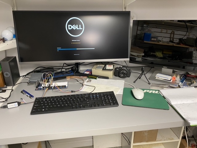
Ordered and got a new Dell computer and added a 34” widescreen monitor to the mix. This makes my old monitor look absolutely puny but the extra wide screen is great for programming since I can have several windows open and not buried anymore. Also since its back up to date again I can run wireless internet back in the basement without having to use flash drives to copy files off the internet to bring downstairs.
I got the P2 mini breakout board installed and ran a couple of test programs on the P2 Edge with no issues.
Started a new version of the Master Controller software via the Spin2 template. First add was the RGB driver that JonnyMac put together for me (thank you so much). His demo worked flawlessly using the 24 RGB LEDs on the robot. Next step was modifying the old display code to match his new driver. His driver code simplified the code I needed to address the LEDs and my updated code worked great.
Next step was testing the multi-port communications setup. I decided to use Cluso99 driver instead of my own as I found some bugs I haven’t been able to resolve yet. His driver has a more complex setup but should work fine for what I need. I ran all his demo programs and studied the code to understand how it works. I created a 2 port test system and got it running properly.
Next step is adding RX into the master from each leg controller to get the feedback data from those controllers.
Got back on converting P1 code from the Master Controller into the new P2 master.
Testing the multi-port comm driver and code conversions to receive feedback data from the legs. So far moving code from P1 to P2 has been fairly easy. Set up a feedback loop using leg 1 initially, it is returning the expected values. Was getting gibberish output for a while until I realized the feedback baud rate was set to 57,900 and not 115,200. I believe I set a lower baud rate on this value as the P1 master was having trouble keeping up and was skipping data coming in. I assume the P2 will be able to handle higher baud rates and will try them out once I get all 6 legs responding.
Next step is creating additional ports for each leg feedback loop and grabbing the leg feedback data. Feedback data consists of the current angle each motor is at, whether or not the motor has finished moving, the direction the motor is moving, is the leg touching the ground, and an error code. Parts of the data are then displayed using the RGB lights for troubleshooting. Other info is used to validate actual leg position vs desired leg position.
I have been following your project, very interesting. A while back you mentioned that you put together a VRUZEND DIY Battery Kit, how is that battery working out for you.
I am considering putting together a VRUZEND 100Ah battery kit, for my Solar station. If I am correct I could put one together for about ~$300, this sure beats the ~$800 for a commercial lithium battery, although I think they use a different lithium chemistry set.
I guess a key component for the battery unit would be the BMS, which one are you using, for your setup, and how is it working out. Not sure which BMS I would have to use for a 100Ah battery.
@Rsadeika said:
I have been following your project, very interesting. A while back you mentioned that you put together a VRUZEND DIY Battery Kit, how is that battery working out for you.
I am considering putting together a VRUZEND 100Ah battery kit, for my Solar station. If I am correct I could put one together for about ~$300, this sure beats the ~$800 for a commercial lithium battery, although I think they use a different lithium chemistry set.
I guess a key component for the battery unit would be the BMS, which one are you using, for your setup, and how is it working out. Not sure which BMS I would have to use for a 100Ah battery.
Ray
The battery is working very well for the purpose I need it for. It powers the motor and computer sides of the electrical system on the robot. I think my setup is only 24Ahr and I haven’t had any issues since they replaced the original BMS under warranty. The BMS I used was the one for 12vdc that Vruzend offers on their website. I don’t remember the max power draw it allows. There are other high-powered BMS’s out there being used in the DIY lithium battery building crowd. I’ve seen several made for RVs that are in the 100-200Ahr range.
Disadvantages of the system are that the battery physical size is going to be larger due to the end terminals, the advantage is the ease of building a battery. If I were going to build a large lithium battery I would be looking into using a DIY spot welder if using a number of smaller cylindrical batteries like Vruzend uses. That allows the most compact battery size.
I’ve spent a lot of time over on the P2 forum side as I add in new code and convert old working P1 code to run on the P2.
The multi-port driver from Cluso99 works pretty good once someone noticed some typing errors in my code that were messing up the expected output. The last problem I have is the input to the P2 was completely stopping after apparently filling the buffer. After a few days of trying to figure out a fix I decided to convert some code JonnyMac developed that worked perfectly for this purpose (it only needed a few tweaks to convert from P1 to P2 spin code).
The feedback code setup is returning motor position (angle), which direction the motor is turning, whether or not the motor has completed the previous request and whether or not the leg is touching the ground from each leg controller to the master. This information is used to control the RGB troubleshooting lights mounted above each leg and initialize several global variables.
Today I set up the transmit comms from the P2 master to the leg controllers. That went very smoothly using the Cluso99 serial driver. Again this needed some work to convert some existing P1 code to P2 but it went very smoothly. I was able to test the setup by selecting individual legs and moving each motor to specific angles.
I have a list of coding I have to convert and test before I can get back to figuring out how to make this walk. I’m especially excited to see how fast the P2 can run and believe the speed issues I had with the P1 are be behind me now. Stay tuned for further updates!
Ran into some issues where the feedback loop is correctly sending individual leg data to the master and I am able to manually use the master to manipulate individual legs. This indicates the transmit and receive functions on the master and slave computers are functioning.
The RGB light system which is updated by the feedback loop ran great on their own but when I put the lighting control routine on its own cog, the LEDs are now flashing instead of staying on continuously. Basic troubleshooting didn’t show the issue but unfortunately I ran out of time to run down the problem.
We left town for our summer holiday so no more work on the robot until we return in September. Then I have all fall and winter to work on it again. Who knew that retiring would leave me less time to work on the robot than when I was working!
We are back from this summer’s travels so I am ready to get back to work on the robot!
I’ve spent a few days getting the electrical system hooked up again and running various test programs to verify all the sensors are working properly.
I found an issue with Leg #4 sensor for identifying the leg is touching the ground. The program wasn’t being triggered with the leg down so hooked a multimeter to the sensor input at the P1 board. It came back reading as an open circuit. So remove the leg, disassemble the lower leg assembly and I found a broken wire to the sensor. So tonight’s project will be fixing that and putting it back together and testing.
I also found an error in the RGB light code that resulted in bad data being displayed, I think its fixed but need to program in a few scenarios to verify its right.
Chip developed a new floating point library for the P2 and I am excited to try that out in the IK routine. Parallax needs to port that to the Prop Tool although I could use Pnut or FlexProp instead.
Glad to see that some people are still following this long running project!
I got leg 4 down sensor fixed and new wire put in. Had to modify the design a bit for running the wire up the leg. The original design had the wire running up inside the lower portion of the tibia tube. However there is a threaded rod inside the tube so I had to put a bunch of slack in the wire so so the wire could wrap around the rod as the threaded end pieces were screwed together. On leg 4 the wire got caught in the threads of the rod and that abraded the wire insulation and eventually broke the wire. I changed the wire route to run outside the tibia tube and use zip ties to hold it in place. This way the wire isn’t affected by twisting the tube but it isn’t as elegant a solution as before.
Ran several of my leg test routines both on individual legs and then as a group. The P2 master is working great so far and looks like a good replacement for the P2 as the master controller.
I enabled the RGB lighting on the robot to test the feedback from the individual legs to the master and found some interesting anomalies that I didn’t see when testing earlier.
From the photo you can see the red lights for the femur and tibia are lit. These are flashing on and off at a regular interval. The red indicates an error condition being transmitted by the individual leg controller, most likely it comes from the encoder not changing values as the motor is stuck in a loop but its already gotten to the requested position. The code is supposed to get out of the movement loop once its reached its position. I think the problem lays where the master is continually blasting the individual legs with commands even if the command is identical to the previous command so the leg gets thrown back into a movement cycle but no further movement is needed.
So I have changes to make to the individual leg controllers to ignore duplicate commands and change the master to reduce the number of duplicates. Then test each code change again!
Bob,
I have been following this project since the very begining. I evén considered buying your old mill, but came to my senses when I thought about transporting it from Mi to Az. Also have a user space issue with 2 Statler Stichers in finished 2 car garage. Keep up the good work, always enjoy following your posts.
Jim
Bob, not sure how far you will be taking this project, but at some point will you be implementing some AI, just to see if your "thing" can figure a way out of the basement.
@Rsadeika said:
Bob, not sure how far you will be taking this project, but at some point will you be implementing some AI, just to see if your "thing" can figure a way out of the basement.


Comments
C hasn’t been too bad to learn so far but I’m still in the very basic stages of it, I’m sure it will get more interesting soon! As it is I tend to make a lot of stupid mistakes that keep things from compiling...
Still looking for a serial communications object that can handle several separate input/outputs. I’ll have to look at the P1 versions of these objects to see if I can convert one over to the P2 if one doesn’t show up by the time I need it. The other thing that needs setting up is the XBee radio, will need to get a interface board since none of the P2 boards have that incorporated and create a P2 object to interface. Lots of stuff to do still but it’s all fun.
Bob
PS. I sold my big metal lathe which required dismantling the hexapod as it was in the way for getting the lathe out of the basement. Finally got the robot back together again (lots more space for testing the legs now!) so hopefully I’ll be able to start testing with the P2 board before too long.
My first adventure was converting the existing Inverse Kinematics (IK) formulas into something that would compile under FlexSpin. First off I had to remind myself about how I went about coming up with the original equations. That required some digging and finding the PDF (see attached) with my calculations.
Next step was entering the equations and lots of work getting the syntax right!
/* Test code for IK entries - fixed inputs for testing purposes */
#include <stdio.h>
#include <math.h>
#include <propeller.h>
#include <simpletools.h>

double coxaLength = 2.5;
double femurLength = 6.0;
double tibiaLength = 25.0;

#define LEDdata  54
#define LEDclock 52

void main()
{
  float degreeValue;
  degreeValue = 45.0;
  /*  getsine(degreeValue); */
  /*  legIK(0.0, 28.0, 11.0); */
}

double to_degrees(double rad)
{
  	return rad * 180.0 / PI;
}
double to_radians(double deg)
{
  	return deg * PI / 180.0;
}

void legIK (double IKx, double IKy, double IKz)
{
  	double L1, L, C, IKb, IKb1, IKb2;
  	double IKfemurAngle, IKtibiaAngle, IKcoxaAngle;

  	L1 = sqrt((IKz*IKz) + (IKx*IKx));

	L = L1 - coxaLength;

  	C = sqrt((IKy*IKy) + (L*L));

  /* IKb = acos(((femurLenth^2 + C^2) - tibiaLength^2) / (2 * femurLength * C))  */
  	IKb = acos(((femurLength*femurLength) + (C*C) - (tibiaLength*tibiaLength)) / (2.0 * femurLength * C));

	IKb2 = atan(L / IKy);

  /* IKb1 = acos((tibiaLength^2 + C^2 - FemurLength^2) / (2 * tibiaLength * C))  */
  	IKb1 = acos(((tibiaLength*tibiaLength) + (C*C) - (tibiaLength*tibiaLength)) / (2.0 * tibiaLength * C));

  	IKfemurAngle = (IKb + IKb2) * (180.0 / PI);
 	IKtibiaAngle = (IKb2 - IKb1) * (180.0 / PI);
 	IKcoxaAngle = atan(IKz + IKx) * (180.0 / PI);

  	printf("L1 = %lf\n", L1);
  	printf("L = %lf\n", L);
  	printf("C = %lf\n", C);
  	printf("IKb = %lf\n", IKb);
  	printf("IKb2= %lf\n", IKb2);
  	printf("IKb1 = %lf\n", IKb1);
  	printf("IKfemurAngle = %lf\n", IKfemurAngle);
  	printf("IKtibiaAngle = %lf\n", IKfemurAngle);
  	printf("IKcoxaAngle = %lf\n", IKcoxaAngle);
}
I got everything up and running faster than I expected, the C math library was much easier to use than floating point on the P1! The test code outputs to a windows terminal window with the calculation results. I'd like to output to the Propeller Serial Terminal (PST) window if I can figure out how to get FlexSpin to change its default output.Now I'm working on getting the robot RGB troubleshooting LEDs to work under P2. The P1 object for the LPD8806 is a combination of Spin and pasm and I'm pretty rusty on assembly. I've been trying out a Spin only bit-banged approach but it isn't working quite right yet. The LPD8806 LED Driver chip appears to be unique and there isn't much out there, even the datasheet doesn't show the timing requirements for the chip. The only other driver I found on-line was written in C for an Arduino so not much help there. I'm about ready to give it up and switch over to the WS2812B RGB modules that Parallax sells. There are several P2 drivers already developed for it.
Bob
Mike
Next is getting a multi-port serial device set up. The P1 master code uses 2, 4 port serial objects. There are 8 serial lines being used; 1 for master to leg controllers (one way comms only), 6 receive lines from each leg controller to the master (one way comms also), and 2 way comms via the PropPlug (mainly for troubleshooting).
I started fiddling with a simple serial driver, jm_serial.spin2, unfortunately I managed to break it and now it isn't responding. JonnyMac recommended that I look into his FullDuplexSerial code as he set it up better for handling multiple ports. So its off to reviewing more code and seeing what it might take to allow it to handle more lines. I have seen that the P2 Smart Pins capabilities are pretty nice and can greatly reduce the amount of setup code needed for tasks like this. Study time again!
Nothing else to update on, still haven't quit on this project!
Back on page 19, you shared that you had to rewrite the encoder code for the HH12 encoders. Are you willing to share that P1 code? I am about to start putting together my bot arm and I would like to use that for positioning. btw do you happen to know if the HH12 is still available?
Jim
Thanks much, I am looking forward to it.
Jim
' encoder mask
con
    CDataIn     := 18    ' input
    CEncoderClk := 16    ' output
    CEncoderCS  := 17    ' output active low
  AngleMask = %111111111111000000
  StatusMask = %000000000000111111

PUB CoxaEncoder | x, rawin, packdata, angledata, statusdata
'' AS4045 magnetic encoder bit-banging routine
  'setup encoder pins
  dira[CDataIn]~
  dira[CEncoderClk]~~
  dira[CEncoderCS]~~
  outa[CEncoderCS]~~ 'take CS pin high
  outa[CEncoderClk]~~ 'take Clk pin high
'  PauseMSec(1)
  outa[CEncoderCS]~ 'CS pin low to start transfer
'  PauseMSec(1) 'for chip response time
  outa[CEncoderClk]~ 'start clocking
'  PauseMSec(1) 'pause 10 msec
  repeat x from 0 to 17
    outa[CEncoderClk]~~
'    PauseMSec(1)   '10ms
    RawIn := ina[CDataIn]        'read raw data from encoder in
    packdata := (packdata << 1) + RawIn
    outa[CEncoderClk]~
'    PauseMSec(1)
  'get angle and status values via masking raw packdata
  result := (packdata & anglemask) >> 6            'AND mask and shift 6 bits
'  statusdata := packdata & statusmask
'  encoderangle := angledata
  'calculate actual angle
'  Encoderangle := (angledata * (8789))/10000
  packdata := 0
The commented out delays may not be required. The statusdata and encoderangle were there for troubleshootingContact Georg Hylinski about the HH-12 via his website: www.DF1SR.de.
DF1SR@Arcor.de
Hope this helps you.
Thanks for digging that out. As soon as I get on my computer, I will try it out.
Thanks again.
Jim
Anyway I have been attending the weekly Parallax Zoom meetings covering the various aspects of the P2. These sessions have been a lot of fun. I've learned a lot just from attending these sessions and have been having some fun playing with P2 spin coding. I really like the P2 Edge board and I got the mini breakout board for it along with the Jon McPhalen Edge Module Breadboard from Parallax. I think the P2 Edge will be make for a nice robot master computer and I want to mount the mini breakout board on the robot computer deck. It should make wiring to the 6 P1 boards fairly easy to do using jumpers.
Here are some dance moves for your hexapod!
[url]
Dennis
It’s been a while since my last update here but I have been active on the Parallax P2 forum instead.
I’m continuing work on a version of a multi-port serial object, lots of studying P2 pasm and other’s code. After several fits and starts I finished up my first version of the code, unfortunately it doesn’t work properly so now I’m using Pnut and debugging to figure out where I’m going wrong.
In the meantime Cluso99 created his own multi-port serial object that seems to work pretty well. I’m still continuing on working on my version as a good excuse to get better at P2 pasm and I’ve designed the interface to the code to be similar to the P1 multi-port serial object I have been using on the master computer. That will make converting my existing master P1 code over to the P2 somewhat easier.
Once I get the serial object running I am going to re-visit coding the inverse kinematics engine using some of the built-in P2 functions instead of running the code in C under FlexProp. I think long term that will make the code easier to maintain instead of having Spin, C, and Pasm all mixed together.
No additional changes to the mechanical features on the robot at this point. After selling my big metal lathe I had to re-assemble the robot and now I have a larger testing area in the basement.
I completed work on the P2 multi-port serial object so moved on to the next item on the to-do list.
I couldn't find my P2 C code I wrote for doing Inverse Kinematics so I re-did the code in FlexProp C and got it working fairly quickly. I really want to do all the coding in Spin2 and PASM so I started looking into creating a math/trig library that I can use. To maximize speed of calculations everything is being designed using integer math. The P2 made sin and cos easy to put together (with some help from others on the forum). arcsin and arccos were a bit more difficult but got help from Eric Smith and that's good to go. Currently working on arctan and atan2. Based on the hints from a couple of forum members, in theory these should be the easiest to do but my brain has gone into a math freeze zone and I am not getting the expected results. Once atan and atan2 are figured out I should have all the objects I need to install the P2 Edge in the robot and start programming it directly again.
I removed the old P1 Activity Board that was acting as the master from the robot. It will be replaced with a P2 Edge board mounted on the mini-breakout board. The holes on the board are much smaller than the holes for on the Activity board, it appears to use metric 2.6 sized screws so I need to get out of the house and down to the hardware store to get the board mounted.
The integer based trig Spin2 library is done and working, so cross that item off the to-do list. It includes sin, cos, tan, arctan, arcsin, arccosine, atan2.
Next item was re-writing the Inverse Kinematics formulas using Spin2. As I was able to compare outputs with the ‘C’ based IK code it was fairly easy to identify issues quickly and fix them. The IK code re-write from P1 to P2 didn’t take as long as I anticipated but it is done and working. I really should do some tests to see how much speed improvement there is using the P2 vs P1 but I believe the speed increase will be significant. The P2 can run at 300Mhz vs 80Mhz and integer math is always going to be faster than floating point math. Even the new version of Spin is faster.
Next item on the list was updating the programming computer in the basement with the new versions of the Propellor Tool (v2.5.2). That turned out to be a tougher problem than anticipated. Turns out that computer runs Windows 7 (64 bit home premium) and has been divorced from any internet/wireless connection for many years. I use flash drives to move needed code to it, turns out the new Propeller Tool installation needs a lot more old Windows updates than expected. It may be time to update that machine to a better Win10 based computer with wireless capability. Since I need to process video data too (even my ‘good’ Win10 computer is getting old and slow for that) that rules out the ‘cheaper’ machines.
Once I get through this hurtle I’ll be installing the new master computer and start hooking up and testing all the connections.
I made a step stool for the lifting hoist, otherwise the legs catch on the corners of the hoist top.
Ordered and got a new Dell computer and added a 34” widescreen monitor to the mix. This makes my old monitor look absolutely puny but the extra wide screen is great for programming since I can have several windows open and not buried anymore. Also since its back up to date again I can run wireless internet back in the basement without having to use flash drives to copy files off the internet to bring downstairs.
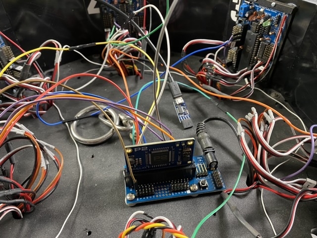
I got the P2 mini breakout board installed and ran a couple of test programs on the P2 Edge with no issues.
Started a new version of the Master Controller software via the Spin2 template. First add was the RGB driver that JonnyMac put together for me (thank you so much). His demo worked flawlessly using the 24 RGB LEDs on the robot. Next step was modifying the old display code to match his new driver. His driver code simplified the code I needed to address the LEDs and my updated code worked great.
Next step was testing the multi-port communications setup. I decided to use Cluso99 driver instead of my own as I found some bugs I haven’t been able to resolve yet. His driver has a more complex setup but should work fine for what I need. I ran all his demo programs and studied the code to understand how it works. I created a 2 port test system and got it running properly.
Next step is adding RX into the master from each leg controller to get the feedback data from those controllers.
Got back on converting P1 code from the Master Controller into the new P2 master.
Testing the multi-port comm driver and code conversions to receive feedback data from the legs. So far moving code from P1 to P2 has been fairly easy. Set up a feedback loop using leg 1 initially, it is returning the expected values. Was getting gibberish output for a while until I realized the feedback baud rate was set to 57,900 and not 115,200. I believe I set a lower baud rate on this value as the P1 master was having trouble keeping up and was skipping data coming in. I assume the P2 will be able to handle higher baud rates and will try them out once I get all 6 legs responding.
Next step is creating additional ports for each leg feedback loop and grabbing the leg feedback data. Feedback data consists of the current angle each motor is at, whether or not the motor has finished moving, the direction the motor is moving, is the leg touching the ground, and an error code. Parts of the data are then displayed using the RGB lights for troubleshooting. Other info is used to validate actual leg position vs desired leg position.
I have been following your project, very interesting. A while back you mentioned that you put together a VRUZEND DIY Battery Kit, how is that battery working out for you.
I am considering putting together a VRUZEND 100Ah battery kit, for my Solar station. If I am correct I could put one together for about ~$300, this sure beats the ~$800 for a commercial lithium battery, although I think they use a different lithium chemistry set.
I guess a key component for the battery unit would be the BMS, which one are you using, for your setup, and how is it working out. Not sure which BMS I would have to use for a 100Ah battery.
Ray
The battery is working very well for the purpose I need it for. It powers the motor and computer sides of the electrical system on the robot. I think my setup is only 24Ahr and I haven’t had any issues since they replaced the original BMS under warranty. The BMS I used was the one for 12vdc that Vruzend offers on their website. I don’t remember the max power draw it allows. There are other high-powered BMS’s out there being used in the DIY lithium battery building crowd. I’ve seen several made for RVs that are in the 100-200Ahr range.
Disadvantages of the system are that the battery physical size is going to be larger due to the end terminals, the advantage is the ease of building a battery. If I were going to build a large lithium battery I would be looking into using a DIY spot welder if using a number of smaller cylindrical batteries like Vruzend uses. That allows the most compact battery size.
I’ve spent a lot of time over on the P2 forum side as I add in new code and convert old working P1 code to run on the P2.
The multi-port driver from Cluso99 works pretty good once someone noticed some typing errors in my code that were messing up the expected output. The last problem I have is the input to the P2 was completely stopping after apparently filling the buffer. After a few days of trying to figure out a fix I decided to convert some code JonnyMac developed that worked perfectly for this purpose (it only needed a few tweaks to convert from P1 to P2 spin code).
The feedback code setup is returning motor position (angle), which direction the motor is turning, whether or not the motor has completed the previous request and whether or not the leg is touching the ground from each leg controller to the master. This information is used to control the RGB troubleshooting lights mounted above each leg and initialize several global variables.
Today I set up the transmit comms from the P2 master to the leg controllers. That went very smoothly using the Cluso99 serial driver. Again this needed some work to convert some existing P1 code to P2 but it went very smoothly. I was able to test the setup by selecting individual legs and moving each motor to specific angles.
I have a list of coding I have to convert and test before I can get back to figuring out how to make this walk. I’m especially excited to see how fast the P2 can run and believe the speed issues I had with the P1 are be behind me now. Stay tuned for further updates!
Ran into some issues where the feedback loop is correctly sending individual leg data to the master and I am able to manually use the master to manipulate individual legs. This indicates the transmit and receive functions on the master and slave computers are functioning.
The RGB light system which is updated by the feedback loop ran great on their own but when I put the lighting control routine on its own cog, the LEDs are now flashing instead of staying on continuously. Basic troubleshooting didn’t show the issue but unfortunately I ran out of time to run down the problem.
We left town for our summer holiday so no more work on the robot until we return in September. Then I have all fall and winter to work on it again. Who knew that retiring would leave me less time to work on the robot than when I was working!
We are back from this summer’s travels so I am ready to get back to work on the robot!
I’ve spent a few days getting the electrical system hooked up again and running various test programs to verify all the sensors are working properly.
I found an issue with Leg #4 sensor for identifying the leg is touching the ground. The program wasn’t being triggered with the leg down so hooked a multimeter to the sensor input at the P1 board. It came back reading as an open circuit. So remove the leg, disassemble the lower leg assembly and I found a broken wire to the sensor. So tonight’s project will be fixing that and putting it back together and testing.
I also found an error in the RGB light code that resulted in bad data being displayed, I think its fixed but need to program in a few scenarios to verify its right.
Chip developed a new floating point library for the P2 and I am excited to try that out in the IK routine. Parallax needs to port that to the Prop Tool although I could use Pnut or FlexProp instead.
Welcome back Bob! You have been quite for a while, but with a good reason") Hope the new floating point makes things easier for you.
Hope the new floating point makes things easier for you.
Looking forward to regular updates, Bob! Once again, Kudos for your dedication & persistence on this long-term project!
Glad to see that some people are still following this long running project!
I got leg 4 down sensor fixed and new wire put in. Had to modify the design a bit for running the wire up the leg. The original design had the wire running up inside the lower portion of the tibia tube. However there is a threaded rod inside the tube so I had to put a bunch of slack in the wire so so the wire could wrap around the rod as the threaded end pieces were screwed together. On leg 4 the wire got caught in the threads of the rod and that abraded the wire insulation and eventually broke the wire. I changed the wire route to run outside the tibia tube and use zip ties to hold it in place. This way the wire isn’t affected by twisting the tube but it isn’t as elegant a solution as before.
Ran several of my leg test routines both on individual legs and then as a group. The P2 master is working great so far and looks like a good replacement for the P2 as the master controller.
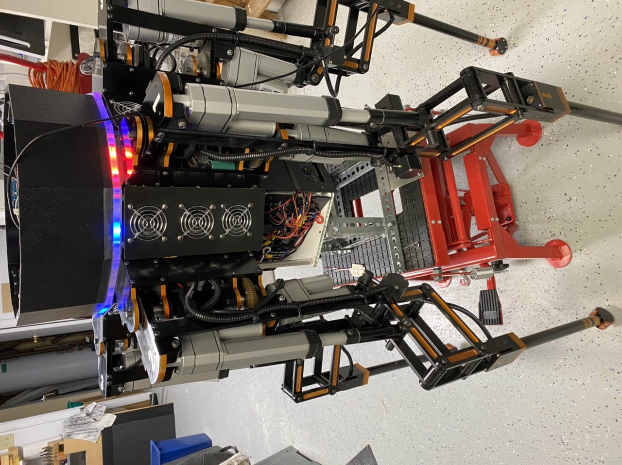
I enabled the RGB lighting on the robot to test the feedback from the individual legs to the master and found some interesting anomalies that I didn’t see when testing earlier.
From the photo you can see the red lights for the femur and tibia are lit. These are flashing on and off at a regular interval. The red indicates an error condition being transmitted by the individual leg controller, most likely it comes from the encoder not changing values as the motor is stuck in a loop but its already gotten to the requested position. The code is supposed to get out of the movement loop once its reached its position. I think the problem lays where the master is continually blasting the individual legs with commands even if the command is identical to the previous command so the leg gets thrown back into a movement cycle but no further movement is needed.
So I have changes to make to the individual leg controllers to ignore duplicate commands and change the master to reduce the number of duplicates. Then test each code change again!
Bob,
I have been following this project since the very begining. I evén considered buying your old mill, but came to my senses when I thought about transporting it from Mi to Az. Also have a user space issue with 2 Statler Stichers in finished 2 car garage. Keep up the good work, always enjoy following your posts.
Jim
DiverBob,
WOW!
As Dave Jones would say, "That is a serious bit of kit!"
Bob, not sure how far you will be taking this project, but at some point will you be implementing some AI, just to see if your "thing" can figure a way out of the basement.
Ray
LOL