Shop OBEX P1 Docs P2 Docs Learn Events
Smartpin Diagram (now with %P..P bit mode table) — Parallax Forums

Smartpin Diagram (now with %P..P bit mode table)

RaymanRayman Posts: 13,800
edited 2024-02-29 16:17 in Propeller 2
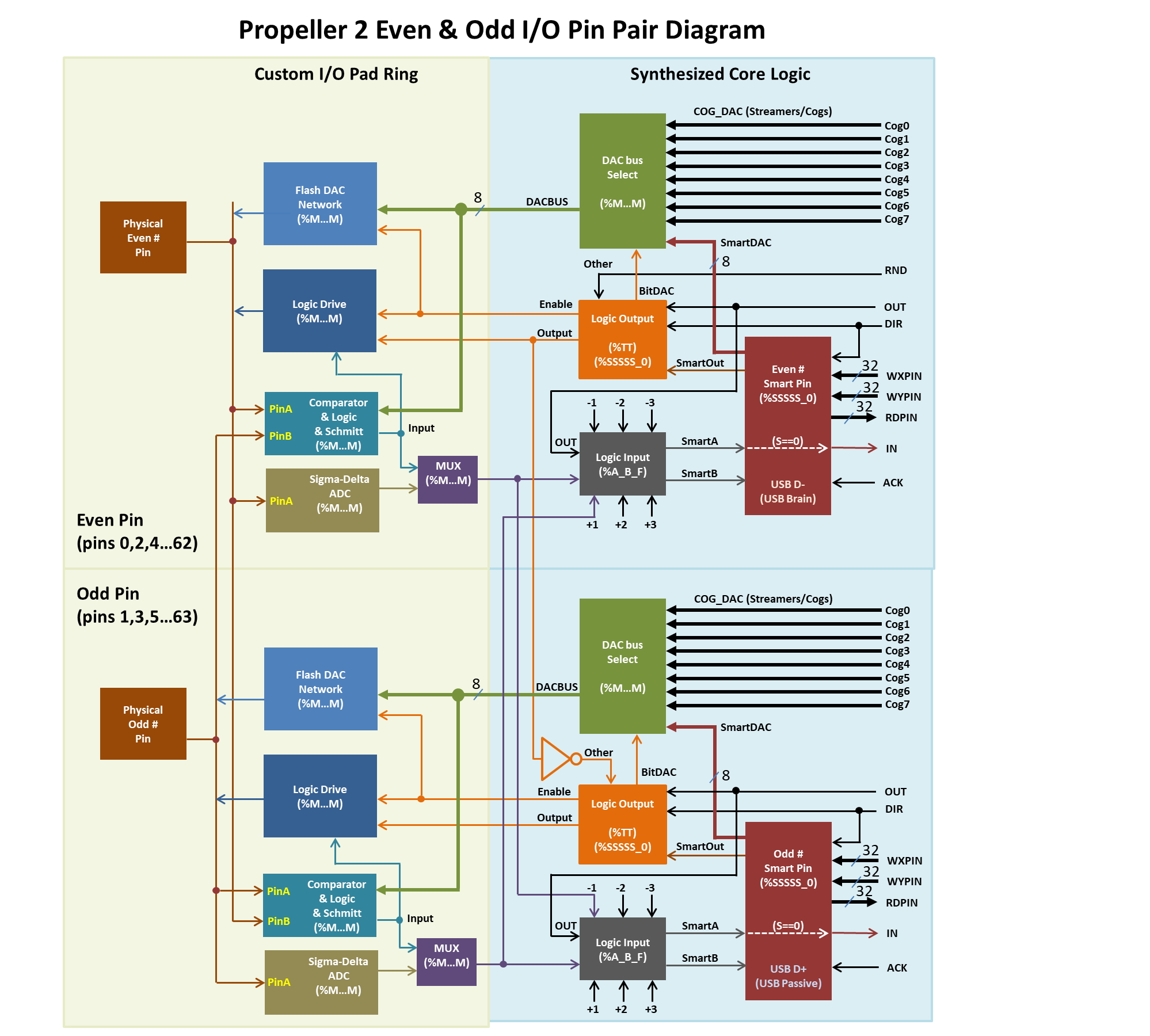
I took a stab at rendering Evanh's ascii art smartpin diagram.
Take a look. I'm open to any suggestions for improvement.
I don't fully understand it yet, but maybe this will help...

Update: Other moved and dac bus select output signals renamed
Update2: After input from Chip
Update3: Added enable for DAC output
Update4: Moved OUT back where it was and added in direct lines to +1 and -1 inputs between pins.
Update5: Added even/odd barrier and labels
Update6: Added USB notes
Update7: Changed feedback to a branch of input
Update8: Relocated "PinA" etc. and renamed Smart_A/B inputs and revised title.
Update9. Removed OutIn and split Out to take it's place.

Update10: Also have a %P..P table.
Update 11: @evanh reminded me to update the diagram here.
Get higher res version here: https://forums.parallax.com/discussion/download/137264/Slide1.PNG
«1345678

Comments

  • That's a great diagram, Ray.
  • kg1kg1 Posts: 164
    edited 2020-04-03 20:00
    It seems that attachments disappear as soon as a comment is saved?
    At first I thought the diagram was on http://www.rayslogic.com/ but no it is another of those forum tricks!
    Perhaps the words could be edited to "Take a look at the attachment below."
    Excellent diagram.
    386 x 278 - 22K
  • Thanks, Ray! It has been printed and posted on my bench!

    This needs to find its way into the "official" P2 documentation.
  • evanhevanh Posts: 15,126
    Thanks Rayman. The colour coding is a nice improvement.
  • evanhevanh Posts: 15,126
    edited 2020-04-03 20:21
    JRoark wrote: »
    This needs to find its way into the "official" P2 documentation.
    I'd love to be able to explode each of those blocks to give even more detail ... but I'd be guessing too much I think. There's already some guessing in that digram.

    EDIT: Mainly the following:
    - "Other" path, was a toss up as how it selects and routes. I've gone with within the custom I/O ring but the T block was another option.

    - OUT looped back to the F block is impacted by DIR if I remember correctly. And is independent of SMART_OUT. This is why I've got it going through the T block first. Relatedly, I've made up the terms driveH/driveL to show a distinction from OUT/DIR. I have no idea if those are representative or not.
  • evanhevanh Posts: 15,126
    Exploded, the T block will be a little spaghetti looking.
  • RaymanRayman Posts: 13,800
    I'm still figuring it out... Some of these are busses, right?
    I think cog0...cog7, RND, driveH, driveL are all busses, right?
    Maybe I should make them thicker to show this...

    I didn't remember there being a difference between even and odd pins except for stuff like USB.
    What is this RND signal that only goes to the even pin? What mode uses that?
    And, what is the purpose of the inverter that goes to the odd pin?
  • Uhmm, both smartpins are labeled as "odd".
  • RaymanRayman Posts: 13,800
    I think the idea there is that the odd smartpin's M setting controls the even pin, like in USB
  • RaymanRayman Posts: 13,800
    I'm trying to add the asci version to the Mixed Signal Scope, but seems I need a vertical scrollbar that I haven't implemented yet...
    4032 x 3024 - 2M
  • evanhevanh Posts: 15,126
    edited 2020-04-03 21:36
    Rayman wrote: »
    I'm still figuring it out... Some of these are busses, right?
    I think cog0...cog7, RND, driveH, driveL are all busses, right?
    Maybe I should make them thicker to show this...
    Only the DAC ones going to the DAC network are 8-bit. Everything else is 1-bit or analogue in the case COMP_DAC and physical pins.

    I didn't remember there being a difference between even and odd pins except for stuff like USB.
    What is this RND signal that only goes to the even pin? What mode uses that?
    And, what is the purpose of the inverter that goes to the odd pin?
    "Other" is the main difference now between odd and even pins. The ADC pairing has been removed. I've not tried to use "other" for anything yet. I'm guessing it's mainly for differential output which presumably USB mode uses.

    Using the RND bit is the alternate pin arrangement for "other". It's simply one bit of the free-running random number hardware in the hub. A different bit for each pin I think, only 32 pins need it.

    EDIT: There is also the comparator making use of pin pairs.

  • evanhevanh Posts: 15,126
    edited 2020-04-03 21:08
    Wuerfel_21 wrote: »
    Uhmm, both smartpins are labeled as "odd".
    Yeah, that was a typo for a while before I corrected it in my own versions.

    EDIT: Doh! I've not updated my forum edition ... corrected - https://forums.parallax.com/discussion/comment/1473762/#Comment_1473762

    PS: The typo was simply a result of text block copying and forgetting to edit it.
  • RaymanRayman Posts: 13,800
    edited 2020-04-03 21:10
    Ok, I can fix that.

    BTW: Isn't it %TT that selects other? Should that be included somehow?

    Update: Fixed even/odd issue
  • evanhevanh Posts: 15,126
    edited 2020-04-03 22:12
    Rayman wrote: »
    BTW: Isn't it %TT that selects other? Should that be included somehow?
    Yep. That was part of the dilemma. Do I add (%TT) to the Pin Output block as well? To be honest, "other" routing may well go through the T block as well so I kind of gave up on that one.
  • evanhevanh Posts: 15,126
    edited 2020-04-03 22:34
    Chip's PNG with the custom I/O modes table doesn't mention a thing about "other". That's sort of telling me it's all mux'd in the T block. The table may not be showing every mode though.

    On that note, DIR and OUT as listed in that table will be as presented to the custom ring rather than as they are at the cogs. So the driveH/L signals I've got will be bogus.

    PNG link - https://forums.parallax.com/discussion/169241/new-pin-instructions/p1

    EDIT: Ah! I've got "other" completely wrong. The docs say "for odd pins, ‘OTHER’ = NOT lower(even) pin’s output state (diff source)". I had took that to mean the physical pin drive but "output state" is more likely to mean the OUT at the custom pin interface. Time for a rework ...

  • evanhevanh Posts: 15,126
    edited 2020-04-18 23:35
    Out of date diagram removed, newer revision - https://forums.parallax.com/discussion/comment/1473762/#Comment_1473762

  • cgraceycgracey Posts: 14,133
    I've tried to get into the schematic for the pin, but Siemens (was Mentor, was TannerEDA before that) has me locked out of the prior versions of the chip tools that I need to open our files. I can't tell you how much I hate this kind of thing. Every time I renew our support, it seems to get more restrictive. I will download the latest version of their schematic software, but I don't think it will open our file properly. Let me see...
  • Cluso99Cluso99 Posts: 18,066
    Ray,
    Great diagram :)

    Evan,
    Is it the PinB to each comparator that has been cut in RevC silicon? If so, perhaps you and Ray can mark this on both drawings :)
  • evanhevanh Posts: 15,126
    edited 2020-04-03 23:36
    I believe it was only the ADC affected. The comparator is unaffected.
    	%100_VVV_OHHHLLL = ADC_MODE, first order sigma-delta
    		IN has bitstream, sysclock bitrate
    		OUT is PinA digital output, registered
    		DIR enables PinA digital output
    		%VVV = ADC config
    			000: GIO, 1x (~5 volt range, centred on VIO/2)
    			001: VIO, 1x       "
    			010: PinB, 1x      "     (In revC silicon this measures the zero-bias point of the ADC)
    			011: PinA, 1x      "
    			100: PinA, 3.16x (~1.58 volt range, centred on VIO/2)
    			101: PinA, 10x   (~0.5 volt range, centred on VIO/2)
    			110: PinA, 31.6x (~0.158 volt range, centred on VIO/2)
    			111: PinA, 100x  (~0.05 volt range, centred on VIO/2)
    
    Ha, an out of date comment about an associated smartpin mode there ... removed
  • evanhevanh Posts: 15,126
    cgracey wrote: »
    I've tried to get into the schematic for the pin, but Siemens (was Mentor, was TannerEDA before that) has me locked out of the prior versions of the chip tools ...
    Seimens PLC tools are similar. Luckily, they're the exception rather than the rule so there is other name brands that are much more end user (electrician) friendly.

  • cgraceycgracey Posts: 14,133
    I am downloading the latest version of the chip design tools now. Last time I tried to use a newer version, the schematic came up all jumbled. I hope they will give me access to the old versions, again. Right now, I am locked out of everything.
  • evanh wrote: »
    cgracey wrote: »
    I've tried to get into the schematic for the pin, but Siemens (was Mentor, was TannerEDA before that) has me locked out of the prior versions of the chip tools ...
    Seimens PLC tools are similar. Luckily, they're the exception rather than the rule so there is other name brands that are much more end user (electrician) friendly.

    No.
    Not true.
    Fifteen years of hearing these attacks.
    Siemens is very good about emergency license activation.

    If licenses get corrupted the machine still runs. Their software is inexpensive if you actually buy parts from them. Development software (everything) was $2000 per year to keep up to date.

    They were very good about getting out patches, and their hotline is free (unlike the other big name)

    If you buy the floating license it never expires.
  • evanhevanh Posts: 15,126
    whicker wrote: »
    ... Their software is inexpensive if you actually buy parts from them. Development software (everything) was $2000 per year to keep up to date.
    That's the inexpensive option is it? USD I presume. It should be $0.00 for the tools, the hardware is the product.
  • evanhevanh Posts: 15,126
    edited 2020-04-04 00:18
    What is an emergency license activation? Money I'm guessing. What happens to the tools if you don't maintain the license each year?
  • RaymanRayman Posts: 13,800
    edited 2020-04-04 01:20
    Used to be able to set clock back a year on pc to still use license
  • cgraceycgracey Posts: 14,133
    Rayman wrote: »
    Used to be able to set clock back a year on pc to still use license

    I might have to try that. Will install new 1GB download now and see what happens.
  • evanh wrote: »
    What is an emergency license activation? Money I'm guessing. What happens to the tools if you don't maintain the license each year?
    Emergency means you can run the development software for 14 days. No charge, just click ok.

    Nothing happens if you stop paying other than you can't use the license on the newer major version. But you never lose what you have.
  • evanhevanh Posts: 15,126
    Not as bad as I thought. The licence terms seem to be okay. I must admit I've been put off by the complexity in the past too. Particularly the opaque function blocks on the series 5, so it a while back. I've not even looked at a series 7.

  • Cluso99Cluso99 Posts: 18,066
    Rayman wrote: »
    Used to be able to set clock back a year on pc to still use license
    Now you have to be connected to the internet, and the software phones home to check.
  • Chip, I'm hoping you have the install files for the older version of tanner eda?

    I'm sure somebody help if you can define the issue a little better.

    Were there any hard copy printouts? Sometimes i'd print my schematics to pdf for review by someone else or as a sanity check.
Sign In or Register to comment.