In my own solution to the thermal challenges on the two layer board I just reverse mounted the P2ME2 board so the P2 chip top faced down, but had a fan below it on the Voyager motherboard circulating some air on top of the P2 plastic case. With this solution there is no need to mount the chip upside down, just the daughter board. I did cut out a fan pattern on the carrier board so air could be sucked in from below. This helped keep the system a lot cooler. I was going to drill holes in the back of the case if I ever found it needed more airflow.
LOL, looking at these pics I just observed I still haven't snipped off those Ethernet module header pins which I kept if the SPI bus needed probing during bringup. Thankfully there's still a bit of clearance above those bent over pins.
@rogloh said:
In my own solution to the thermal challenges on the two layer board I just reverse mounted the P2ME2 board so the P2 chip top faced down, but had a fan below it on the Voyager motherboard circulating some air on top of the P2 plastic case.
Yes, that was very nifty.
I wonder if a fan-facing P2 board like that, would benefit from carefully placed and sized holes, to allow some of the fan-air to pass thru the board ?
@jlsilicon said:
4. Mount / solder a Large Heatsink / wind-tunnel on the now Top (chip bottom Gnd plane) etc.
That doesn't work unless you take a copper heatsink. You need to connect the ground pad which is the same as the thermal pad. AND make sure that the heatsink has a low impedance path to the ground plane of the PCB. A "pig tail" connection with a wire doesn't work for high frequency.
The thing is, we do not know what the intended use is hence it is not easy to address the need properly and give advice towards the solution. I've proven myself wrong many times when doing things according to the general guidelines (they were too relaxed for the intended use case) and sometimes it is not necessary to obey them and the thing works better than expected.
@rogloh said:
In my own solution to the thermal challenges on the two layer board I just reverse mounted the P2ME2 board so the P2 chip top faced down, but had a fan below it on the Voyager motherboard circulating some air on top of the P2 plastic case. With this solution there is no need to mount the chip upside down, just the daughter board. I did cut out a fan pattern on the carrier board so air could be sucked in from below. This helped keep the system a lot cooler. I was going to drill holes in the back of the case if I ever found it needed more airflow.
Couldn't you Mount/solder a Heatsink to the Board bottomside Gnd - then use the fan ...
Good you got your boards back so quickly @jlsilicon . Was this a 4 layer board in the end or 2 layers? It will be interesting to learn the maximum frequency these boards will reach and how any supply noise / thermal limits affect things once you are up and running.
For accurate silkscreen font sizing/positioning you can use vector fonts in your layout software. It looks a bit like some labels got shifted around or made the wrong size perhaps by the PCB fab house. I think this can happen if you don't select vector fonts in the labels.
Found 1 Error : on the Dip Board : disconnected Chip Vdd from +3.3V - forgot to re-route it.
Just needed a wire to reconnect and solder across - used bottom of VRegOut connect to bottom Cap Vdd under the chip.
I wired it up according to Minimal Connect Schematic :
As Below :
The port pins travel around, starting with Pin0 at Lower Left 2nd pin , around CounterClockwise, to p63 at Upper Left last 2nd pin , (skipping 4 corner pins).
Corner pins are Lower Left corner Gnd (Brown Wire) , Lower Right corner pin VIn+ (but using 2pin VIn connector here) , Upper Right corner pin Gnd (Brown Wire), Upper Left corner pin VReg 3.3V VOut+ (not used here) .
Board also has a few 0.1uF Caps that you can't see in the photo.
( You can see at the top , that I also added a LED via 470R resistor to p56 - to test the Blink2.prop2 code )
But, running Propeller2 IDE , does not see the Device (Propeller2) ; I checked the Port, and clicked Detect repeatedly.
Prop2 IDE - sees the Ft232 port (port15), but does Not see the Prop2.
This propeller Plug was already tested successfully on the Prop1 Dip IC.
Ok, I plugged the Reset (Green Wire) in wrong place - should be on the top of 5pins SIP (actually 3pin next to 2pin Reset Btn).
A Note - for the P2 High Speed 300MHz+ power noise issues :
-- I found that in sensitive devices , projects use a large Cap (10uF - 100uF) at Board Voltage In.
-- And, dual Caps 0.1uF with 10nF paired parallel together around the device PowerIn pins - to reduce very small voltage noise.
Found 1 Error : on the Dip Board : disconnected Chip Vdd from +3.3V - forgot to re-route it.
Just needed a wire to reconnect and solder across - used bottom of VRegOut connect to bottom Cap Vdd under the chip.
You mean Vdd to 1.8v, right?
The VIO (i/o pin drivers) connect to 3.3v, the core Vdd needs 1.8v
I soldered chip to 2nd new board, and wired it up.
I switched VIn+ from FTD32 3.3V to 5V.
I tried FlexProp, and loaded Blink.prop2 , compiled and ran it.
-- The terminal first said no prop2, second run gave a "checksum error".
I tried SpinToolsIDE again, clicked Detect Device multiple times.
-- It popped up the Prop2 abount 1 out of 6 times, but could not Upload - just returned " error no Prop2 found "
So, the Boards should be successful !
... just need to get circuitry refined (Caps etc).
I was getting Detect every other click.
And I uploaded Blink to board a few times ;
-- Wrong Blink though - it used Ext Clk - so I could not see it running successfully.
I added 1uF and 0.1uF and 10uF caps across both Vdd 1.8V , and Vio 3.3V .
Now I can't Detect at all.
-
I am Confused,
I added the Caps - now I don't detect the P2 on either board at all.
Without the Caps, sometimes I could detect the P2 on both boards ... -- Does this make sense ???
Why ??
You are using a USB to serial converter of some type (like an FTDI cable) instead of a PropPlug in your breadboard picture. What is the reset circuitry path to the P2 from the converter?
Please look up "ground plane" on Wikipedia. Your ground ring with a narrow track around the board makes a good dipole antenna but is quite bad for a digital circuit running at a high frequency. This is asking for trouble and I doubt that it will ever run reliably. I don't say that it's impossible to make a working two-layer board with the P2 but it requires some experience with HF layouts.
However, the "detect" function of the Propeller Tool should work anyways because it only depends on the internal RC clock of the P2, AFAIK, and only uses P62 and P63.


Comments
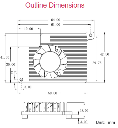
Any new P2 PCB design could also allow a couple of holes for this :: (Adafruit have this Pi5 cooler, Heatsink + fan for $5)
addit : here is an Pi5 cooler alternative from waveshare, has more dimensions
Might be a good idea. A case could also include a fan...
This is what got me thinking about different Board designs :
https://nutsvolts.com/magazine/article/an-introduction-to-the-parallax-propeller-2
In my own solution to the thermal challenges on the two layer board I just reverse mounted the P2ME2 board so the P2 chip top faced down, but had a fan below it on the Voyager motherboard circulating some air on top of the P2 plastic case. With this solution there is no need to mount the chip upside down, just the daughter board. I did cut out a fan pattern on the carrier board so air could be sucked in from below. This helped keep the system a lot cooler. I was going to drill holes in the back of the case if I ever found it needed more airflow.
LOL, looking at these pics I just observed I still haven't snipped off those Ethernet module header pins which I kept if the SPI bus needed probing during bringup. Thankfully there's still a bit of clearance above those bent over pins.
Yes, that was very nifty.
I wonder if a fan-facing P2 board like that, would benefit from carefully placed and sized holes, to allow some of the fan-air to pass thru the board ?
That doesn't work unless you take a copper heatsink. You need to connect the ground pad which is the same as the thermal pad. AND make sure that the heatsink has a low impedance path to the ground plane of the PCB. A "pig tail" connection with a wire doesn't work for high frequency.
The thing is, we do not know what the intended use is hence it is not easy to address the need properly and give advice towards the solution. I've proven myself wrong many times when doing things according to the general guidelines (they were too relaxed for the intended use case) and sometimes it is not necessary to obey them and the thing works better than expected.
Couldn't you Mount/solder a Heatsink to the Board bottomside Gnd - then use the fan ...
Yes one could do that. In my own tablet application I had clearance issues on that surface so I didn't do it like that.
Ordered both boards : P2ExpPCB & P2Dip3 .
Boards were shipped today.
Waiting on the boards to arrive.
Boards in already ! - that was fast .
I opened the package, and just had to solder one of the chips down.
Below, soldered down and mounted :
Looks great !
The separated Breadboards allow a Heatsink to project underneath the Dip Board - while mounted on the breadboards.
Next : Setting up a minimum board test ...
Good you got your boards back so quickly @jlsilicon . Was this a 4 layer board in the end or 2 layers? It will be interesting to learn the maximum frequency these boards will reach and how any supply noise / thermal limits affect things once you are up and running.
For accurate silkscreen font sizing/positioning you can use vector fonts in your layout software. It looks a bit like some labels got shifted around or made the wrong size perhaps by the PCB fab house. I think this can happen if you don't select vector fonts in the labels.
Any pictures of the underside of your boards?
Only 2-Layer.
Just needed a wire to reconnect and solder across - used bottom of VRegOut connect to bottom Cap Vdd under the chip.
I wired it up according to Minimal Connect Schematic :
As Below :
The port pins travel around, starting with Pin0 at Lower Left 2nd pin , around CounterClockwise, to p63 at Upper Left last 2nd pin , (skipping 4 corner pins).
Corner pins are Lower Left corner Gnd (Brown Wire) , Lower Right corner pin VIn+ (but using 2pin VIn connector here) , Upper Right corner pin Gnd (Brown Wire), Upper Left corner pin VReg 3.3V VOut+ (not used here) .
Board also has a few 0.1uF Caps that you can't see in the photo.
( You can see at the top , that I also added a LED via 470R resistor to p56 - to test the Blink2.prop2 code )
But, running Propeller2 IDE , does not see the Device (Propeller2) ; I checked the Port, and clicked Detect repeatedly.
Prop2 IDE - sees the Ft232 port (port15), but does Not see the Prop2.
This propeller Plug was already tested successfully on the Prop1 Dip IC.
Ok, I plugged the Reset (Green Wire) in wrong place - should be on the top of 5pins SIP (actually 3pin next to 2pin Reset Btn).
A Note - for the P2 High Speed 300MHz+ power noise issues :
-- I found that in sensitive devices , projects use a large Cap (10uF - 100uF) at Board Voltage In.
-- And, dual Caps 0.1uF with 10nF paired parallel together around the device PowerIn pins - to reduce very small voltage noise.
There is some pull-up settings that decides boot mode. Might want to make sure you have pull-up in place to say check serial for boot
Also try using FlexProp as it doesn’t need crystal to be working
The voltage regulators probably don't like the lack of capacitors. They may well be oscillating.
You mean Vdd to 1.8v, right?
The VIO (i/o pin drivers) connect to 3.3v, the core Vdd needs 1.8v
Yeah, you are right, power is connected backwards...
Hope I did not burn the chip out.
PCB Board Bare, Top and Bottom :
I am close now !
I soldered chip to 2nd new board, and wired it up.
I switched VIn+ from FTD32 3.3V to 5V.
I tried FlexProp, and loaded Blink.prop2 , compiled and ran it.
-- The terminal first said no prop2, second run gave a "checksum error".
I tried SpinToolsIDE again, clicked Detect Device multiple times.
-- It popped up the Prop2 abount 1 out of 6 times, but could not Upload - just returned " error no Prop2 found "
So, the Boards should be successful !
... just need to get circuitry refined (Caps etc).
Ok.
I built a 2nd board.
I was getting Detect every other click.
And I uploaded Blink to board a few times ;
-- Wrong Blink though - it used Ext Clk - so I could not see it running successfully.
I added 1uF and 0.1uF and 10uF caps across both Vdd 1.8V , and Vio 3.3V .
Now I can't Detect at all.
-
I am Confused,
I added the Caps - now I don't detect the P2 on either board at all.
Without the Caps, sometimes I could detect the P2 on both boards ...
-- Does this make sense ???
Why ??
You are using a USB to serial converter of some type (like an FTDI cable) instead of a PropPlug in your breadboard picture. What is the reset circuitry path to the P2 from the converter?
It works on programming the P1 DIP chips with no prob.
I tested VRegs 3.3V and 1.8V - voltages good on both boards.
Please look up "ground plane" on Wikipedia. Your ground ring with a narrow track around the board makes a good dipole antenna but is quite bad for a digital circuit running at a high frequency. This is asking for trouble and I doubt that it will ever run reliably. I don't say that it's impossible to make a working two-layer board with the P2 but it requires some experience with HF layouts.
However, the "detect" function of the Propeller Tool should work anyways because it only depends on the internal RC clock of the P2, AFAIK, and only uses P62 and P63.
I agree, I am aware of ground plane.
But I am just aiming right now to get it booting at Low CLK Speed.
I think that reset circuit is wrong…
I’ll look mine up
Think needs pull-up