@evanh said:
Might be okay for safety. But you still want an operational ability to hold position with no power right?
Yes of course, there will some method to hold the main shaft if no power. Probably redundancy. If the VFD will release this motor's brake nicely at some
low RPM and the brake plays nicely through the desired range of speeds, then the built in brake(on the splined
motor shaft - PRE-gearing) is a good thing since its holding force is quite robust POST- gears. It is a trivial matter to add a shaft brake to the main shaft that drives the 4 lifting cables. I intend to add two 72 tooth ANSI 35 sprockets to the main 1" keyed shaft just to have it there in case I want add other stuff ie brakes, dampers etc. Dropping in a different chain driven brake motor would be simple do to later with a sprocket or two already on the shaft. I'll probably have one of those inertia brakes as well, not much money around $350 would be a nice comfort level based on it's specs. Waiting to hear back from the tech guys about that concept.
It is hard to say just yet if this is viable. The motor moves fine. The brake releases at 10Hz on start, drops out around 5 on stop. After running for a full 25' cable length, the brake started some erratic behavior, random chatter. Luckily for the first test the brake behavior for releasing early on is a good sign.
I got an error message and it stopped running. But it started right back up. Runs of more than a few seconds are prone to the brake chatter but only gave the error and shut down once. There is no way to know how it will behave under load. The settings are factory. Except it came with a 10 second accel/decel setting and I changed it to 4 seconds which is still too long for my needs. It sounds like an old lawnmower, but I don't care about the sound if it will work. I need to read the manual and try to replicate the error since I didn't write it down and see what it says.
The error I have gotten a few times is OC-R. It seems the motor and brake are fine for a very short while. Then after some time maybe 30-60 seconds you hear brake chatter and things get erratic for a second and it stops. But it will start right back up and run a bit. There is not excessive heat touching the motor, warm maybe but not hot. I could raise the projector platform I estimate in 1-2 minutes 10’ most likely but this erratic behavior is not going to be acceptable. Looking online trying to find a similar size wire rope hoist with 3 phase motor. I really like the ability to ramp and decel with a knob on this vfd so this concept is the way to go.
I suppose I should remove the brake drum and see if the error persists. Then decide if an exterior brake method is the compromise. There is a splined D shaft 2” long sticking off the motor where a fan mounts. I could add the shaft brake there and maybe have an assignable relay in the vfd drive the brake when stopped. I tested it and a relay is assignable and will fire at all times when the motor is stopped.
I started working on the math for cable length and ratios. The platform will move 120". Based on the ratios of 2:1 off the hoist cable drum to the larger drum it spins, the cable drum needs to spin 12 revolutions. With no load, at 50Hz, the drum can spin 38 times in 60 seconds. This means this motor needs to run less than 15 seconds to go from up to down. I don't know how the 400lb load will affect speed going back up.
I took out the brake drum, with no load the motor runs 30 seconds before glitching, shuts off with error at 35 seconds. Same overload error as noted earlier. With brake back in, one test started glitching at 1 minute 30 seconds. Glitched over 30 seconds here and there and stopped with the same error.
Wait a while, got it to run 1 minute before first glitch. It never glitches early on, so maybe I can get by with this overload error at 60 seconds. Even the motor originally states never run more than 2 minutes On, 8 off.
Working on a way to lift 400lb 5feet to see how the vfd works with loads. If there is no errors on consistent tests moving the load, I think this is a viable solution since I really only need speed reduction near the top when it needs to slow down to line itself up with the ceiling guides and hit a limit switch.
Regardless it is a nice learning curve as it is good to finally understand what a vfd does.
In looking at other 3 phase hoists, I see 2 speed hoists, most are 1 speed. I don't see a lot of variable speeds. However, these all are getting very pricey. For system that may run once a year why spend thousands. I found some low cost green color wire rope hoists on ebay, new, that list 380V. I asked if these can be wired as a 3phase for vfd, waiting for reply.
Hmm, crappy manual. Both in Chinglish and overly cautious.
Actually, the drive seems to be missing any current limit parameters. Nor even a spec. Normally those should be obvious. The OC-R error gives no indication of how much current it is tripping at.
@"T Chap" said:
Yes I thought I had addressed that earlier. It seems exactly like that only using 2 of the 100uf caps.
The wiring, confirm the order of the wiring. Does the 200 uF capacitor actually sit across the Red and Blue motor wires. And that Red and Blue are controlled like I drew.
@"T Chap" said:
I see no method of limiting. I assume the motor starts getting warm and the controller detects an overload as current increases.
That's a good example of the poor documentation. It's not an increase in current that is tripping out, it's the thermal I2T calculation. When it says "Steady State" it is talking about a time induced trip. Those sort of parameters are normally configurable on VSDs, but they're all missing in the manual.
Ouch, seems display has no list of display items. Normally you'd expect it to be running selectable through a list of items like Set Hz, Out Hz, Current and Voltage at least. So, we can't get a reading on what the drive is doing. Not unless there is a better manual somewhere else.
By default it is showing the running freq. It may be selectable to show other parameters.
I just disconnected the caps and the motor was already disconnected from the original switching boxes. So I can do better end to end metering. They change colors from cord input to the up down buttons, e stop button, up limit switch etc so it’s a brain twister to chase this out the changing colors.
One side of the cap is permanently to attached to motor wire Red(Up). The other side of the cap(s) connects to blue when up or down is pressed.
Oddly, with no motor connected, no caps, no obvious components just switches and wire, i connect 120VAC and in the up down remote I can find 120VAC, 47VAC and 59VAC!
I am not apposed to getting a better vfd. I had no idea what to buy or look for. Just guessing. And it had a knob on front which is part of my goal to dial the speed.
The wiring, confirm the order of the wiring. Does the 200 uF capacitor actually sit across the Red and Blue motor wires. And that Red and Blue are controlled like I drew.
@"T Chap" said:
By default it is showing the running freq. It may be selectable to show other parameters.
I'm not seeing anything selectable in the manual, sadly.
One side of the cap is permanently to attached to motor wire Red(Up). The other side of the cap(s) connects to blue when up or down is pressed.
That's odd. Are you able to make a drawing?
Oddly, with no motor connected, no caps, no obvious components just switches and wire, i connect 120VAC and in the up down remote I can find 120VAC, 47VAC and 59VAC!
That'll be floating volts from stray capacitive coupling of the nearby live wires. Some multimeters have a second AC position that loads the probes so that stray voltage is drained to show there is no power.
What I said was not clear. The cap is not connected on one leg until the switch is pressed for up or down. Once you press up or down then the cap is connected to red and blue. The up and down button cuts the cap when not pressed. One leg of the cap is always connected to red. Blue gets connected while pressing either up or down button on their hand held remote. The caps are removed when using vfd. Although I read online somewhere that vfd needs caps also. But I’m not clear if they should be in or not in vfd. Doesn’t make sense they would need caps with vfd.
I understood what you said. Placing a switch in that position in the wiring is what doesn't make sense ... How about more of what you first did - Take a photo with all wires visible in the long "chocolate block" terminal. They aren't all clear in the existing photo.
Err. they are all visible. Just finish labelling them then.
After an hour of chasing down the all the crazy wiring I know what is going on. They are disconnecting one side of the cap when a button is not pressed. I removed the unnecessary wiring such as Estop, upward motion limit switch as they don't benefit for the discussion of motor windings and caps.
There is a DPDT style control, 2 buttons. Up and Down. The buttons must be pressed and held to move up and down. When the buttons are pressed, it routes 120VAC to EITHER motor RED or motor BLUE. Part of the switch also connects one side of the cap to motor RED. They apparently went to some effort to not let the cap stay in the circuit when not on.
Evanh, your circuit was technically correct, but this shows the exact function. Color coding and labeling the rats nest of wires is doable but this is much simpler to view, as you'd have to chase out multiple wires that change colors at every connection point, as route out to Estop and limit switches. Note: On the VFD, there are no caps connected now.
Thanks for the suggestions on this! Lots of fun trying to make this work. I realize I may need to look for a vfd with current control?
That's just weird. It will work but it appears pointless extra wiring and switches. Now I want to work out what the wiring is for the brake. Maybe that will shed light on why the capacitor is switched out like that.
When running does it have some DC voltage sitting on it? The motor windings would dead short the cap. Faster decel? No Idea. The red blue and black wires enter to the coil nearest the brake. Could be the wires are wound so either polarity pulls the brake drum in.
@"T Chap" said:
What if they don't want the cap to lose any charge when off? When running does it have some DC voltage sitting on it? I can check but it's wired to vfd right now. The motor windings would dead short the cap. Faster decel? No Idea.
No, the brake stops it dead anyway. There's no good reason I can think of to do that for the motor.
The red blue and black wires enter to the coil nearest the brake. Could be the wires are wound so either polarity pulls the brake drum in.
That picture doesn't show any wiring to the brake. That's just the motor windings.
There are no wires to the brake, only red blue black to the motor windings. The motor windings are pulling the brake in towards the windings, compressing a spring. The brake drum lives on a splined shaft and slides in towards the motor when the motor turns on.
Oh ... you probably could have mentioned that a little earlier. I have no idea how that'll interact, it's bound to be complicating things inductively ...
EDIT: Ah, you've had the brake out and it faulted even quicker then. Hmm.


Comments
Yes of course, there will some method to hold the main shaft if no power. Probably redundancy. If the VFD will release this motor's brake nicely at some
low RPM and the brake plays nicely through the desired range of speeds, then the built in brake(on the splined
motor shaft - PRE-gearing) is a good thing since its holding force is quite robust POST- gears. It is a trivial matter to add a shaft brake to the main shaft that drives the 4 lifting cables. I intend to add two 72 tooth ANSI 35 sprockets to the main 1" keyed shaft just to have it there in case I want add other stuff ie brakes, dampers etc. Dropping in a different chain driven brake motor would be simple do to later with a sprocket or two already on the shaft. I'll probably have one of those inertia brakes as well, not much money around $350 would be a nice comfort level based on it's specs. Waiting to hear back from the tech guys about that concept.
It is hard to say just yet if this is viable. The motor moves fine. The brake releases at 10Hz on start, drops out around 5 on stop. After running for a full 25' cable length, the brake started some erratic behavior, random chatter. Luckily for the first test the brake behavior for releasing early on is a good sign.
I got an error message and it stopped running. But it started right back up. Runs of more than a few seconds are prone to the brake chatter but only gave the error and shut down once. There is no way to know how it will behave under load. The settings are factory. Except it came with a 10 second accel/decel setting and I changed it to 4 seconds which is still too long for my needs. It sounds like an old lawnmower, but I don't care about the sound if it will work. I need to read the manual and try to replicate the error since I didn't write it down and see what it says.
The error I have gotten a few times is OC-R. It seems the motor and brake are fine for a very short while. Then after some time maybe 30-60 seconds you hear brake chatter and things get erratic for a second and it stops. But it will start right back up and run a bit. There is not excessive heat touching the motor, warm maybe but not hot. I could raise the projector platform I estimate in 1-2 minutes 10’ most likely but this erratic behavior is not going to be acceptable. Looking online trying to find a similar size wire rope hoist with 3 phase motor. I really like the ability to ramp and decel with a knob on this vfd so this concept is the way to go.
I suppose I should remove the brake drum and see if the error persists. Then decide if an exterior brake method is the compromise. There is a splined D shaft 2” long sticking off the motor where a fan mounts. I could add the shaft brake there and maybe have an assignable relay in the vfd drive the brake when stopped. I tested it and a relay is assignable and will fire at all times when the motor is stopped.
Is there a PDF manual for the drive I can look at?
Sure this is it thanks for any suggestions!
https://m.media-amazon.com/images/I/A1WMEfiE8lL.pdf
I started working on the math for cable length and ratios. The platform will move 120". Based on the ratios of 2:1 off the hoist cable drum to the larger drum it spins, the cable drum needs to spin 12 revolutions. With no load, at 50Hz, the drum can spin 38 times in 60 seconds. This means this motor needs to run less than 15 seconds to go from up to down. I don't know how the 400lb load will affect speed going back up.
I took out the brake drum, with no load the motor runs 30 seconds before glitching, shuts off with error at 35 seconds. Same overload error as noted earlier. With brake back in, one test started glitching at 1 minute 30 seconds. Glitched over 30 seconds here and there and stopped with the same error.
Wait a while, got it to run 1 minute before first glitch. It never glitches early on, so maybe I can get by with this overload error at 60 seconds. Even the motor originally states never run more than 2 minutes On, 8 off.
Working on a way to lift 400lb 5feet to see how the vfd works with loads. If there is no errors on consistent tests moving the load, I think this is a viable solution since I really only need speed reduction near the top when it needs to slow down to line itself up with the ceiling guides and hit a limit switch.
Regardless it is a nice learning curve as it is good to finally understand what a vfd does.
In looking at other 3 phase hoists, I see 2 speed hoists, most are 1 speed. I don't see a lot of variable speeds. However, these all are getting very pricey. For system that may run once a year why spend thousands. I found some low cost green color wire rope hoists on ebay, new, that list 380V. I asked if these can be wired as a 3phase for vfd, waiting for reply.
I had hoped you'd double check the original wiring was as I drew up in post #42 - https://forums.parallax.com/discussion/comment/1555381/#Comment_1555381
And requested a particular detail in post #56 - https://forums.parallax.com/discussion/comment/1555400/#Comment_1555400
Yes I thought I had addressed that earlier. It seems exactly like that only using 2 of the 100uf caps.
Hmm, crappy manual. Both in Chinglish and overly cautious.
Actually, the drive seems to be missing any current limit parameters. Nor even a spec. Normally those should be obvious. The OC-R error gives no indication of how much current it is tripping at.
I see no method of limiting. I assume the motor starts getting warm and the controller detects an overload as current increases.
The wiring, confirm the order of the wiring. Does the 200 uF capacitor actually sit across the Red and Blue motor wires. And that Red and Blue are controlled like I drew.
That's a good example of the poor documentation. It's not an increase in current that is tripping out, it's the thermal I2T calculation. When it says "Steady State" it is talking about a time induced trip. Those sort of parameters are normally configurable on VSDs, but they're all missing in the manual.
Ouch, seems display has no list of display items. Normally you'd expect it to be running selectable through a list of items like Set Hz, Out Hz, Current and Voltage at least. So, we can't get a reading on what the drive is doing. Not unless there is a better manual somewhere else.
I should have asked for the manual earlier.
By default it is showing the running freq. It may be selectable to show other parameters.
I just disconnected the caps and the motor was already disconnected from the original switching boxes. So I can do better end to end metering. They change colors from cord input to the up down buttons, e stop button, up limit switch etc so it’s a brain twister to chase this out the changing colors.
One side of the cap is permanently to attached to motor wire Red(Up). The other side of the cap(s) connects to blue when up or down is pressed.
Oddly, with no motor connected, no caps, no obvious components just switches and wire, i connect 120VAC and in the up down remote I can find 120VAC, 47VAC and 59VAC!
I am not apposed to getting a better vfd. I had no idea what to buy or look for. Just guessing. And it had a knob on front which is part of my goal to dial the speed.
Thanks for looking at the manual. This is what you see on the controller.
Yes. And yes. All the same.
I'm not seeing anything selectable in the manual, sadly.
That's odd. Are you able to make a drawing?
That'll be floating volts from stray capacitive coupling of the nearby live wires. Some multimeters have a second AC position that loads the probes so that stray voltage is drained to show there is no power.
Same as your drawing only move one end of the cap before the direction switch.
It doesn't make sense to me. You're gonna have to draw that out for me.
What I said was not clear. The cap is not connected on one leg until the switch is pressed for up or down. Once you press up or down then the cap is connected to red and blue. The up and down button cuts the cap when not pressed. One leg of the cap is always connected to red. Blue gets connected while pressing either up or down button on their hand held remote. The caps are removed when using vfd. Although I read online somewhere that vfd needs caps also. But I’m not clear if they should be in or not in vfd. Doesn’t make sense they would need caps with vfd.
I understood what you said. Placing a switch in that position in the wiring is what doesn't make sense ... How about more of what you first did - Take a photo with all wires visible in the long "chocolate block" terminal. They aren't all clear in the existing photo.
Err. they are all visible. Just finish labelling them then.
For such infrequent use, why does this thing even need to be electrically powered? Wouldn't Block and Tackle suffice?
Say what? You want people to do manual labor!!
After an hour of chasing down the all the crazy wiring I know what is going on. They are disconnecting one side of the cap when a button is not pressed. I removed the unnecessary wiring such as Estop, upward motion limit switch as they don't benefit for the discussion of motor windings and caps.
There is a DPDT style control, 2 buttons. Up and Down. The buttons must be pressed and held to move up and down. When the buttons are pressed, it routes 120VAC to EITHER motor RED or motor BLUE. Part of the switch also connects one side of the cap to motor RED. They apparently went to some effort to not let the cap stay in the circuit when not on.
Evanh, your circuit was technically correct, but this shows the exact function. Color coding and labeling the rats nest of wires is doable but this is much simpler to view, as you'd have to chase out multiple wires that change colors at every connection point, as route out to Estop and limit switches. Note: On the VFD, there are no caps connected now.
Thanks for the suggestions on this! Lots of fun trying to make this work. I realize I may need to look for a vfd with current control?
That's just weird. It will work but it appears pointless extra wiring and switches. Now I want to work out what the wiring is for the brake. Maybe that will shed light on why the capacitor is switched out like that.
When running does it have some DC voltage sitting on it? The motor windings would dead short the cap. Faster decel? No Idea. The red blue and black wires enter to the coil nearest the brake. Could be the wires are wound so either polarity pulls the brake drum in.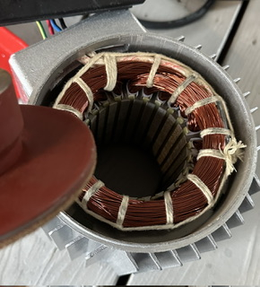
No, the brake stops it dead anyway. There's no good reason I can think of to do that for the motor.
That picture doesn't show any wiring to the brake. That's just the motor windings.
There are no wires to the brake, only red blue black to the motor windings. The motor windings are pulling the brake in towards the windings, compressing a spring. The brake drum lives on a splined shaft and slides in towards the motor when the motor turns on.
Oh ... you probably could have mentioned that a little earlier. I have no idea how that'll interact, it's bound to be complicating things inductively ...
EDIT: Ah, you've had the brake out and it faulted even quicker then. Hmm.