

Speed control for hoist?
 T Chap
Posts: 4,260
T Chap
Posts: 4,260
Hello all this is too fast for the requirement. Lifting a very expensive 350 lb film projector and need more finesse. There is a switch attached to the trip arm, if I toggle that switch fast by hand on/off I can get some PWM that kind of works, but it is also turning the brake on and off at the same time which is very loud. A worst case is connecting some optofet to the switch and setting some frequency maybe with P1 to find a good rate. I haven’t taken it apart yet to see if there is an access to control the motor separately by chopping it and not chop the brake.
Any thoughts?
PS. This only runs once or twice a year for service. I have some built in gearing with the cable system but not enough. I want 50% speed.
Comments
Of course open the control/J box up, inquiring minds want to know...Name plate photo? AC/DC, assuming AC by appearance. Probably going to use an SCR type control? Looking at 15 to 30 bucks.
I will open Sunday so the first step is to find the motor connector and see what the voltage is? After that trace those wires to where they go and see if there actually is some motor controller versus a simple relay. If the motor is AC I have done stuff before using zero crossing detector to P1 and do some slow rate PWM ie a few phases on a few phases off and find the right combo. If DC determine the voltage and amps and maybe use mosfet chopping it with a P1 as controller.
It has a electro break inside also.
It’s only wires and caps inside. Kinda narrows things down. Rated at 18 Amps. Not sure what kind of control that will need.
What about this.
https://lnztech.com/products/ac-110v-220v-25a-10000w-variable-speed-controller-scr-voltage-power-regulator?currency=USD&variant=42654825250975&utm_medium=cpc&utm_source=google&utm_campaign=Google Shopping&stkn=965b9110120a&gclid=EAIaIQobChMIpdaq4pu9ggMVjIFaBR1kYgSIEAsYAyABEgLYAvD_BwE
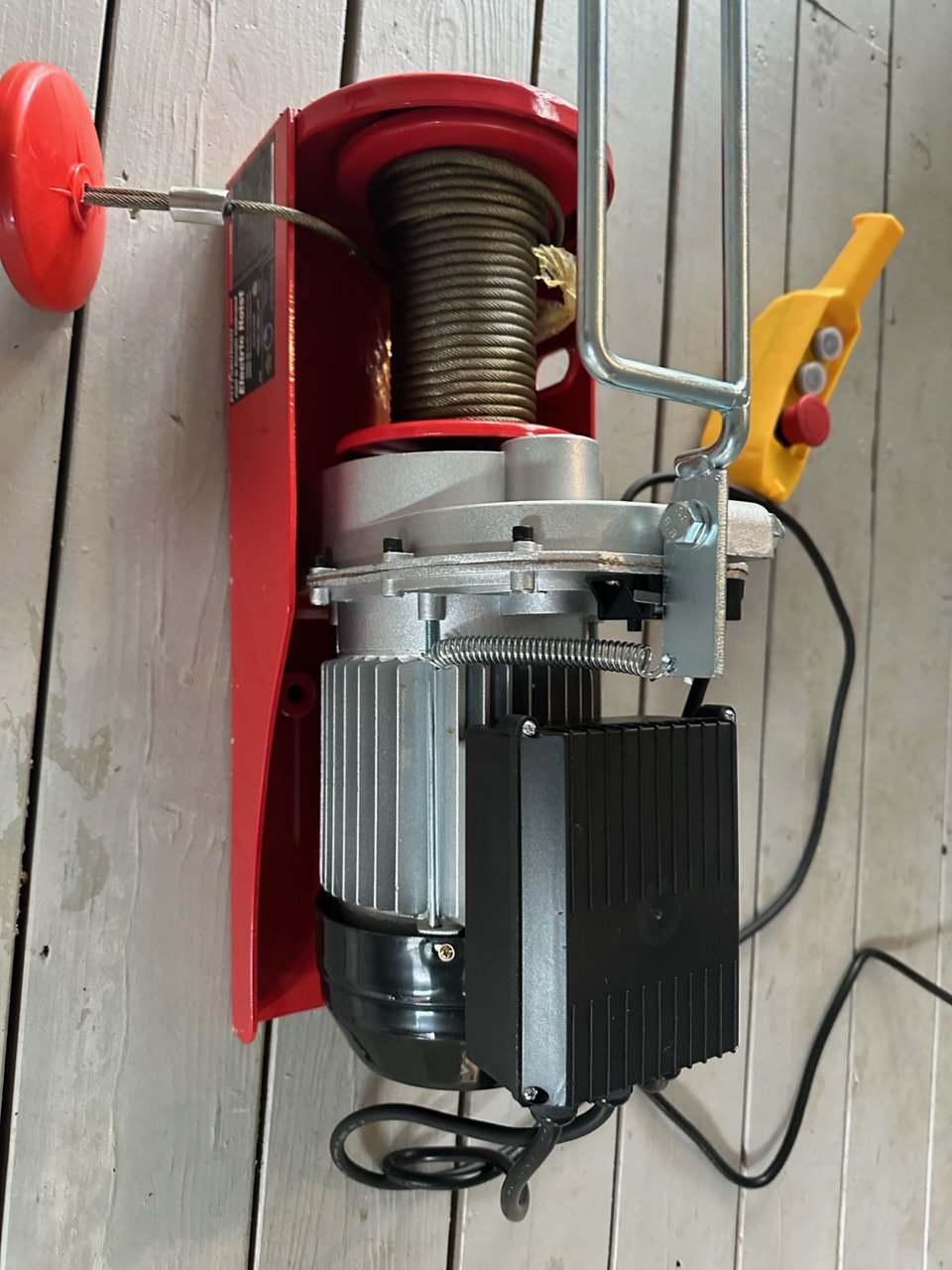
It is not as simple as I had hoped. There are no components except the 2 large caps. I don’t know these motors but just guessing one is a start cap for forward direction and the other a start cap for reverse. Going from the wiring bloc into the motor is 4 wires. Green goes to motor aluminum case. If you remove black you hear nothing. If you remove red you get the release brake noise (loud clack) but only motor hum but no turn. If you remove blue you get the loud break clack and motor hum but no turn.
It appears the power to the brake comes from the same wires to the motor. Somehow they get forward and reverse with red blue and black and also the break turns on. So without digging deeper I can’t know how the break is connected. The goal is to leave the break voltage at maximum and speed control the motor. If I can get access to the break electromagnetic wires internally then I can run them to a separate switch and the find some speed control just for the motor AC in. Trying to speed control the main AC wires in may not have full power to have the brake not operate fully to disengage when the motor should be running
Is there a model number on the motor itself? Have you ohm'd out the Red, Black, and blue wires?
I can meter it in a few. Harbor freight 2000lb. Hope to see if I can get to the brake wires internally.
Apparently the brake is held against a plate with a spring. When power is applied to the motor for either direction the brake disc gets pulled towards the motor, compressing the spring, so the motor can spin. There are not separate wires for brake and motor. This means that my only hope is if using some speed reducer controller will allow some speed reduction while still providing enough force on the brake spring to let it turn.
Yeah, schematic.
It's amazing the difference between various single phase AC motor wiring.
Shouldn't need separate caps for fwd/rev.
Thinking that one of the caps is for the brake.
There is no schematic I can find, will need to make it. The caps are wired in parallel but one is flipped polarity. There are no wires to control the brake, it’s all the same motor coils pulling the brake in towards the motor. Maybe a speed control box will give it enough power at lower speeds to pull the magnet in but that’s a guess. The hoist cable runs to a drum on a shaft. The shaft has 4 other drums / cables that do the lifting. I could put a shaft brake on the main shaft with the hoist motor cable attached and remove the brake inside the hoist motor, then do speed control to the hoist motor and not worry whether the internal brake will release.
Since you're after half speed, could you tie the end of the rope to the roof, and add a new pulley half way between to lift the projector? You'd get half the speed, but also half the height
Those type caps are non-polarised.
The brake probably has no electrical wiring at all. It'll rely on the motor torque to release it.
If you want to experiment, borrow a VSD. I haven't tried but they can probably handle having a single phase motor wired up. But then again, it may just fault out on third phase missing. Hence the borrowing.
Best way to get full control is stump up for a small 3-phase motor with similarly small VSD for reliable frequency control.
Maybe, but limited I suspect. You'll note their list doesn't include single-phase induction motors. Coarse chopping of the AC will play havoc with those capacitors.
"excitation motors" is brushed DC with field electromagnet.
"power tools" and "hand-held routers" are series-wound DC, works almost as well on AC.
"fans" tend to use shaded pole induction. They're weak but forgiving.
All the rest are resistive elements.
Thanks for the suggestions. There is probably 2:1 reduction off the hoist motor/cable to the drum it spins then to the object getting lifted so I do have around 1/2 speed built in. What I was hopping for was a graceful accel/decel moving 400LB up and down with a number of start stops. The idea was to have a knob to turn to start motion, which accelerates non abruptly. Then to stop turn the knob back down to slow the speed before stopping.
There is a chance the motor would hold the 400LB in place even without a brake due to the internal gearing plus external 2:1. Which means I am thinking to remove the brake drum and if needed add a shaft electro brake and control it separately. The projector is locked into position with other clamps when at the top so it cannot fall. This would simplifythe speed control of the hoist motor to not need to consider the brake, just need to find the method. I looked at VFD for single phase and everywhere I read said don't try it. The motor info claims 14A, but I have not checked it with a meter but I could only check it under no load. I wonder what these big variacs would do.
Again, maybe somewhat. By lowering the voltage you'll increase the inductive slip and thereby reduce speed a little but torque will probably collapse quite abruptly. I honestly don't know for sure. Single phase motors suck.
Thanks Evan, all I have to use is 120VAC. Going to some 3phase system would be a challenge.
The VSD runs from single-phase supply. It can take DC even. So electrically it's simple to go to a 3-phase motor. Just need a 3-phase induction motor rated for 200 Vac in Star (120 Vac in Delta). 240 Volt (Star) motor would also be acceptable configured as delta.
TChap - Not sure what your budget is, but a torroidal transformer would be a better option than a Variac if you just want half the output.
Just be sure you have proper mounting for the torroidal transformer... i.e. no metal loops through center and to the chassis that could form a secondary winding.
https://www.digikey.com/en/products/detail/triad-magnetics/VPT100-25000/2090171
We used a similar transformer in an industrial application where we needed 170 VAC pulling 26 Amps form a standard 110VAC outlet... In our case the secondary of the transformer (55VAC) was phase aligned and placed in series with the 110VAC mains resulting in 165VAC being delivered to a heating element. In your case the secondary 55VAC would go directly to your motor.
Thanks Beau. I will have the red Variac linked above on Wednesday. Then I’ll know how that goes. I really am hoping for some ability to accelerate and decelerate versus hard start and stops.
I'm seen a DC motor which runs on 120VAC. This motor had a "Low Speed" switch. The switch routed the AC power through a diode. It's low speed mode used half of the AC cycle for power.
I don't know if something similar would work for you or not. I haven't read the thread enough to know if your motor is the brushed DC variety.
If your motor is the right kind to use the diode hack, maybe you could place the diode to allow full power to electronics but only half power to the motor.
Duane,
That's known as a series-wound "universal" motor. Commonly used by power tools and older home appliances. Like you say, it's a brushed DC motor. The difference from a regular brushed DC motor is the field winding and armature winding are in series with each other instead of being independent. The series arrangement means that it always torques in one direction even when the current is reversed with an AC supply.
So, no, the pictured AC induction motor is not the same. It requires AC to induce a magnetic field, from the field windings, into its rotor's laminated steel plates, which replaces armature windings. And therefore is also brushless.
Hi,
I have had success using an AC drive on a capacitor motor like that. It is not ideal, and will get the motor very hot in the long run, but will provide any speed at almost full torque. After removing the capacitors, you will find 3 terminals actually go to the windings. these hook to the output of the AC drive. (Yes, the voltages/phase angle will be wrong.. but 'good enough' for intermittent use) Most AC drives have outputs that can be configured to operate the brake as well. Such drives abound on Amazon.. even with 110V single phase input.
One advantage is to set the 'ramp' to 1 second or so so you can 'bump' the control for VERY fine control.
With ramp, there will be a tendency to release the brake too soon, so the load may tend to drift down a bit before raising. this can be overcome by setting the 'Min Hz' to something like 15 or so. (1/4 speed...)
Be aware that any malfunction caused by using this suggestion.. or for that matter, any of the others may cause the load to drop in an uncontrolled manner.. For an 'expensive' projector and the sake of your appendages, I would suggest using a better hoist, or a manual chainfall, which would give perfect control..
The red variac linked about doesn't reduce speed at all. It just makes the motor hum loudly when you reduce it below half, then it stops working below half. No speed reduction at all.
Hmm, okay, that's probably the capacitors increasing the kick they give. It will be stressing them.
The motor has 3 wires. Red blue and black. Black is connected to neutral (white) on the main cord. If you connect 120AC to red you get forward. 120AC to blue you get reverse. The brake drum gets pulled in magnetically with either method. I will have 2:1 reduction anyway so maybe I can get by as is. If a vfd would work then a few hundred bucks would be worth it.
R Baggett has the info. It's not perfect but does work when not used 100% duty. Removing the capacitors and treating it as a 3-phase motor makes sense.
“Such drives abound on Amazon.. even with 110V single phase input.”
are we talking just any vfd, just select the amps similar to what this is rated at 14A? 110vac in 3 phase out.
The goal is to turn a know from the lowest possible speed to start it loving. Then ramp it back down to stop. I don’t believe that a hoist that is designed for a maximum 1000 pounds would actually allow gravity and weight too let this thing fall rapidly. I would assume the gear ratio is so high that even without a break you still wouldn’t be able to spin it. I am going to install some sprockets so I can add some chain drive to a shaft mount speed dampening device if I feel like it.
https://www.amazon.com/HKS-Variable-Frequency-Controller-Converter/dp/B09W2LVJGP
Yep, that one is fine. 3KW is way overkill but nothing wrong with overkill. I removed the tracking codes from the link - https://www.amazon.com/HKS-Variable-Frequency-Controller-Converter/dp/B09W2LVJGP
Yep, it'll do speed ramping at programmed slopes. The drive will have multiple switch/button inputs you can configure for various functions.
So I guess there is still a question mark on exactly how the brake will behave. It is needed. Without the brake, and unpowered, that gearbox will unwind with a weight on it for sure. A worm gearbox would hold against weight but this is just a couple of ordinary sprocket gears.