From a non-electronic view, what about a lift stand/crane with enough height for a pulley system plus the distance needed to lift the projector. Some have winches mounted on them, some don't. If this is not a frequent requirement, perhaps rent instead of build or buy.
@"T Chap" said:
The red variac linked about doesn't reduce speed at all. It just makes the motor hum loudly when you reduce it below half, then it stops working below half. No speed reduction at all.
Motor speed is a function of the applied line frequency in this case. Reducing the voltage will reduce the force the motor can produce. Reduce it far enough, the motor will not move and could be fried.
I can add shaft mounted electro brakes and shaft speed reducing dampening. Hopefully the brake will release with some lower speed just experiment to find the value that the brake has enough juice to release.
@"T Chap" said:
I can add shaft mounted electro brakes and shaft speed reducing dampening. Hopefully the brake will release with some lower speed just experiment to find the value that the brake has enough juice to release.
My knowledge of reactance sucks. The concern is that as the modulated frequency drops at slower speeds the DC resistance of the electromagnet will become dominant, this will create large current and large heating. The brake may have to be removed as well.
On the other hand, the drive's switching carrier frequency may play to our favour and mitigate the problem. Selecting a noisy low frequency carrier might be the solution. 4 kHz is usually an option. Worth experimenting with whatever the VSD offers.
I am building a test rig to see how it works with the right weight. I’ll get that vfd and see how it works. Thanks for the ideas, very informative. I’ve wanted to understand this stuff for a while since there are other applications for speed control or large motors. The hoist cable goes around the largest diameter drum on a shaft which spins 4 drums with the 4 cables to the platform.
The VFD is supposed to arrive tomorrow(Sat) and I am trying to understand what R Baggett is suggesting.
In the images attached, I drew the best I can understand of these windings. The motor itself has only 3 wires, not including the green wire from the outer shell to earth. Red, Blue, Black. Black is tied directly to AC IN Neutral, nothing else. Blue is UP, meaning it has 120VAC connected to it via the switch. Red is DOWN.
If Blue has 120VAC going to it, then voltage from Red to Neutral will have 160 VAC.
If Red has 120VAC going to it, then voltage from Blue to Neutral will have 160 VAC.
I assume this means there are 2 separate windings, one for up and one for down.
Both windings when energized will pull the brake rotor IN towards the motor, releasing it against the outside friction plate.
After removing the capacitors, you will find 3 terminals actually go to the windings. these hook to the output of the AC drive. (Yes, the voltages/phase angle will be wrong.. but 'good enough' for intermittent use)
So I will remove the caps! Connect only the 3 motor wires to the VFD
Intermittent for me is DOWN for a few minutes. Then later on UP for a few minutes. Rarely used meaning a few times a year.
With ramp, there will be a tendency to release the brake too soon, so the load may tend to drift down a bit before raising. this can be overcome by setting the 'Min Hz' to something like 15 or so. (1/4 speed...)
On this VFD, there are a ton of settings! "0-400HZ Output 40A Variable Frequency Drive Controller Vector Control Inverter Converter for CNC Motor and Spindle" I will try to find the minimum Hz.
In the information, it looks like I can have external inputs that can be used for UP, DOWN, and set a POT for speed using a voltage divider with 5VDC.
The goal as I see it now is to press DOWN to lower, have the POT turned to it's lowest setting. The as it starts to lower at it's lowest "workable speed" turn the speed knob up to get it going faster. Adjust the speed as desired, slowing it to a graceful slowest speed to get ready to stop. At the bottom, there will be a cable tension sensor that will press a button when cable tension becomes slack, thus telling the motor to stop. To raise, press an UP button, with the POT already at it's lowest setting, then increase the speed to the desired speed for most travel, then slowly decel as it reaches it's top position in which a limit switch will be configured to stop the motor.
Questions
How does my motor connect their wiring scheme?
What would be the ideal initial testing settings to try to avoid damage to the motor?
Touching the Black wire( neutral on motor) to red is .9ohms.
Touching the Black wire( neutral on motor) to blue is .9ohms.
Touching red on motor and blue on motor is 1.5ohms. So this is in line with what you described. There is no way to visually diagnose all the windings.
Looks like each winding is .6ohms. Combine the windings you get 1.2ohms.
@"T Chap" said:
My meter leads touching together is .3ohms.
Touching the Black wire( neutral on motor) to red is .9ohms.
Touching the Black wire( neutral on motor) to blue is .9ohms.
Touching red on motor and blue on motor is 1.5ohms. So this is in line with what you described. There is no way to visually diagnose all the windings.
Looks like each winding is .6ohms. Combine the windings you get 1.2ohms.
Looks good. Confirms black wire is the common for the two phase windings.
EDIT: Also confirms they are equal windings too.
@"T Chap" said:
If Blue has 120VAC going to it, then voltage from Red to Neutral will have 160 VAC.
If Red has 120VAC going to it, then voltage from Blue to Neutral will have 160 VAC.
I assume this means there are 2 separate windings, one for up and one for down.
Not quite. Both windings are needed. The capacitors create a leading phase shift on the alternate winding. Like stepper motors, if you lead/lag one phase over the other then you get to control the direction of rotation.
Both windings when energized will pull the brake rotor IN towards the motor, releasing it against the outside friction plate.
I'm not yet sure how the brake is activated. Have you found any wires for it?
There are no wires obvious to the brake. I can take it back apart tomorrow. I put a photo of the brake drum and the windings earlier. I don’t know if that copper winding that is near the brake rotor would be able to produce a pull or not. But when you energize the motor, it is for sure pulling the brake drum in magnetically compressing a spring that takes a good bit of force by hand to do maybe five or 10 pounds.
Actually, there is a safety concern with the 3 kW overkill of the drive. That'll have larger internal electrical storage - which means it can run on without mains supply. This needs tested to see how far and if this distance can stop without mechanically straining the obstruction cutout.
The obstruction cutout will be regarded as human safety rated. So that needs to be fool-proof and overrides anything the VSD might do. It was in series with the control switches when everything was direct wired single-phase, but with the VSD you now need to make a parallel circuit for the cutout that removes power from either the VSD or from the motor. If the motor then probably want to consider using a contactor to break all three motor wires.
Yes there will be an E Stop switch to kill everything while moving if needed. I'm adding some dampers to the shaft, one way speed reducers to limit the speed on a free fall. When up, it is locked in position with the heavy duty clamps.
Just a thought. I could put a shaft mounted encoder on the main 1” drive shaft. Check the pulses for speed with a P1 board and kill all connections and engage a shaft mount brake if speed > X.
I have this 16NM shaft brake. 24V I’m adding a large 8” chained sprocket to the main drive shaft so I have some options to attach gadgets like dampers and brakes with various gear ratios.
@"T Chap" said:
Just a thought. I could put a shaft mounted encoder on the main 1” drive shaft. Check the pulses for speed with a P1 board and kill all connections and engage a shaft mount brake if speed > X.
Anything you do with the brake has be safety rated. Using a microcontroller would need to be done using a recognised safety rated controller. Best to stick to switches and contactors ... and possibly a safety relay in the middle.
The moment the brake is separated from the direct energising of the motor then it becomes tricky to solve.
@"T Chap" said:
Any guess as to wiring the motor up?
The three motor wires go into U, V and W of the drive. Order doesn't matter, it only affects direction of rotation.
EDIT: Forward and reverse don't have much meaning but if you wanted Up = Forward and Down = Reverse and they were opposite that then swap the Red and Blue wires.
PS: There may be a convention for 3-phase motors to be wound to give a consistent direction of rotation at one end of the motor so that like for like can be exchanged and they give the same direction of rotation when wired with the same order of U, V and W. But I doubt it's something you could rely on.
Ok. I’ll put the neutral common wire to what they show as a black wire to W. Then my red to U and blue to V. First I’ll try to assign the knob to frequency. Then push the forward button and turn the knob, try for 1 second to see if there is any movement and no smoke! Experiment with frequency to see what is the min and max that makes sense. Try to get forward and reverse motion. After that do some longer runs to see what the heat is going to be like running for a few minutes.
I'd also like verification that the direction control my earlier schematic is a match. Particularly that the capacitor is across Red and Blue motor wires.
There are 2 capacitors. I posted a photo of them earlier today. Tomorrow I can check how exactly they connect to the motor. It’s tricky because things are routed around the up down buttons, estop button, upward limits button.
I found these rolling door safety brakes that lock the shaft if it exceeds a certain speed. Requiring the brake to be reset to use again. Some have my 1” keyed shaft size.
@"T Chap" said:
I found these rolling door safety brakes that lock the shaft if it exceeds a certain speed. Requiring the brake to be reset to use again. Some have my 1” keyed shaft size.
Might be okay for safety. But you still want an operational ability to hold position with no power right?
No need to reinvent the wheel. I would go with a Astro E2200 traction hoist. They use three of these to hoist the No. 2 engine down on the McDonell Douglas DC-10. I ran a single VFD in V/F mode to power all three in sync.


Comments
From a non-electronic view, what about a lift stand/crane with enough height for a pulley system plus the distance needed to lift the projector. Some have winches mounted on them, some don't. If this is not a frequent requirement, perhaps rent instead of build or buy.
Motor speed is a function of the applied line frequency in this case. Reducing the voltage will reduce the force the motor can produce. Reduce it far enough, the motor will not move and could be fried.
I can add shaft mounted electro brakes and shaft speed reducing dampening. Hopefully the brake will release with some lower speed just experiment to find the value that the brake has enough juice to release.
My knowledge of reactance sucks. The concern is that as the modulated frequency drops at slower speeds the DC resistance of the electromagnet will become dominant, this will create large current and large heating. The brake may have to be removed as well.
On the other hand, the drive's switching carrier frequency may play to our favour and mitigate the problem. Selecting a noisy low frequency carrier might be the solution. 4 kHz is usually an option. Worth experimenting with whatever the VSD offers.
I am building a test rig to see how it works with the right weight. I’ll get that vfd and see how it works. Thanks for the ideas, very informative. I’ve wanted to understand this stuff for a while since there are other applications for speed control or large motors. The hoist cable goes around the largest diameter drum on a shaft which spins 4 drums with the 4 cables to the platform.
Looks like that vfd arrives this weekend. I will need to figure out with wiring scheme.
Cool. Good luck. Yeah, I keep telling myself to read more about this too.
In my city there is an AM talk radio station with a guy advertising vfd’s all the time with zero explanation of what it does or who the end user is.
Oh, no I meant I keep meaning to read more about reactance, reluctance, impedance, that sort of stuff.
VSDs as just common as mud in industrial environments. Single phase motors got the boot decades ago.
The VFD is supposed to arrive tomorrow(Sat) and I am trying to understand what R Baggett is suggesting.
In the images attached, I drew the best I can understand of these windings. The motor itself has only 3 wires, not including the green wire from the outer shell to earth. Red, Blue, Black. Black is tied directly to AC IN Neutral, nothing else. Blue is UP, meaning it has 120VAC connected to it via the switch. Red is DOWN.
If Blue has 120VAC going to it, then voltage from Red to Neutral will have 160 VAC.
If Red has 120VAC going to it, then voltage from Blue to Neutral will have 160 VAC.
I assume this means there are 2 separate windings, one for up and one for down.
Both windings when energized will pull the brake rotor IN towards the motor, releasing it against the outside friction plate.
So I will remove the caps! Connect only the 3 motor wires to the VFD
Intermittent for me is DOWN for a few minutes. Then later on UP for a few minutes. Rarely used meaning a few times a year.
On this VFD, there are a ton of settings! "0-400HZ Output 40A Variable Frequency Drive Controller Vector Control Inverter Converter for CNC Motor and Spindle" I will try to find the minimum Hz.
In the information, it looks like I can have external inputs that can be used for UP, DOWN, and set a POT for speed using a voltage divider with 5VDC.
The goal as I see it now is to press DOWN to lower, have the POT turned to it's lowest setting. The as it starts to lower at it's lowest "workable speed" turn the speed knob up to get it going faster. Adjust the speed as desired, slowing it to a graceful slowest speed to get ready to stop. At the bottom, there will be a cable tension sensor that will press a button when cable tension becomes slack, thus telling the motor to stop. To raise, press an UP button, with the POT already at it's lowest setting, then increase the speed to the desired speed for most travel, then slowly decel as it reaches it's top position in which a limit switch will be configured to stop the motor.
Questions
Thanks for all the tips on this!
We should probably double check the existing wiring. Here's what the basic circuit of a single-phase motor should be like. See if you can match it up.
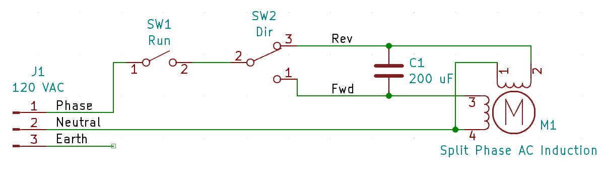
EDIT: Cleaner looking diagram
EDIT2: Typo fix.
My meter leads touching together is .3ohms.
Touching the Black wire( neutral on motor) to red is .9ohms.
Touching the Black wire( neutral on motor) to blue is .9ohms.
Touching red on motor and blue on motor is 1.5ohms. So this is in line with what you described. There is no way to visually diagnose all the windings.
Looks like each winding is .6ohms. Combine the windings you get 1.2ohms.
Looks good. Confirms black wire is the common for the two phase windings.
EDIT: Also confirms they are equal windings too.
Not quite. Both windings are needed. The capacitors create a leading phase shift on the alternate winding. Like stepper motors, if you lead/lag one phase over the other then you get to control the direction of rotation.
I'm not yet sure how the brake is activated. Have you found any wires for it?
There are no wires obvious to the brake. I can take it back apart tomorrow. I put a photo of the brake drum and the windings earlier. I don’t know if that copper winding that is near the brake rotor would be able to produce a pull or not. But when you energize the motor, it is for sure pulling the brake drum in magnetically compressing a spring that takes a good bit of force by hand to do maybe five or 10 pounds.
Actually, there is a safety concern with the 3 kW overkill of the drive. That'll have larger internal electrical storage - which means it can run on without mains supply. This needs tested to see how far and if this distance can stop without mechanically straining the obstruction cutout.
The obstruction cutout will be regarded as human safety rated. So that needs to be fool-proof and overrides anything the VSD might do. It was in series with the control switches when everything was direct wired single-phase, but with the VSD you now need to make a parallel circuit for the cutout that removes power from either the VSD or from the motor. If the motor then probably want to consider using a contactor to break all three motor wires.
Yes there will be an E Stop switch to kill everything while moving if needed. I'm adding some dampers to the shaft, one way speed reducers to limit the speed on a free fall. When up, it is locked in position with the heavy duty clamps.
Okay, cool. For testing the red hoist assembly, just remove the rope so it can spin without potential for obstruction.
Just a thought. I could put a shaft mounted encoder on the main 1” drive shaft. Check the pulses for speed with a P1 board and kill all connections and engage a shaft mount brake if speed > X.
I have this 16NM shaft brake. 24V I’m adding a large 8” chained sprocket to the main drive shaft so I have some options to attach gadgets like dampers and brakes with various gear ratios.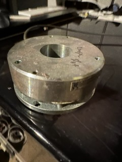
Anything you do with the brake has be safety rated. Using a microcontroller would need to be done using a recognised safety rated controller. Best to stick to switches and contactors ... and possibly a safety relay in the middle.
The moment the brake is separated from the direct energising of the motor then it becomes tricky to solve.
Any guess as to wiring the motor up?
The three motor wires go into U, V and W of the drive. Order doesn't matter, it only affects direction of rotation.
EDIT: Forward and reverse don't have much meaning but if you wanted Up = Forward and Down = Reverse and they were opposite that then swap the Red and Blue wires.
PS: There may be a convention for 3-phase motors to be wound to give a consistent direction of rotation at one end of the motor so that like for like can be exchanged and they give the same direction of rotation when wired with the same order of U, V and W. But I doubt it's something you could rely on.
Ok. I’ll put the neutral common wire to what they show as a black wire to W. Then my red to U and blue to V. First I’ll try to assign the knob to frequency. Then push the forward button and turn the knob, try for 1 second to see if there is any movement and no smoke! Experiment with frequency to see what is the min and max that makes sense. Try to get forward and reverse motion. After that do some longer runs to see what the heat is going to be like running for a few minutes.
I'd also like verification that the direction control my earlier schematic is a match. Particularly that the capacitor is across Red and Blue motor wires.
There are 2 capacitors. I posted a photo of them earlier today. Tomorrow I can check how exactly they connect to the motor. It’s tricky because things are routed around the up down buttons, estop button, upward limits button.
I found these rolling door safety brakes that lock the shaft if it exceeds a certain speed. Requiring the brake to be reset to use again. Some have my 1” keyed shaft size.
I can see they are wired in parallel with each other. 100 uF each. So they act as one 200 uF capacitor.
Might be okay for safety. But you still want an operational ability to hold position with no power right?
No need to reinvent the wheel. I would go with a Astro E2200 traction hoist. They use three of these to hoist the No. 2 engine down on the McDonell Douglas DC-10. I ran a single VFD in V/F mode to power all three in sync.