@rogloh said:
Here's the test code I used for the above:
Ah, that's only one of the four combinations of clock/data pin registration.
It's the one I use for writes, and the address phase for reads. For data reads, I can select registered/unregistered data. I'm not going to bother with supporting unregistered clocks for PSRAM. It was only experimentally added to mess about with HyperRAM at sysclk/1. Registered clock outputs are far more constrained and better to use in general, rather that have some arbitrary internal P2 delay added to the clock.
In order to further explore the "meanders" of such "marriage", between P2 abilities and PSRams, without needing a full-fledged (bandwidth), highly-depth-memory-equipped logic analyzer, it would be good to be able to sync two Cogs and their Streamers, so as to "craft" both the "stable" data, and corresponding (someway "temptative") CE#/CLK-sequencing.
The main burden would be ensure both Streamers are ever (and exactly) synchronized to the same Sysclk, but CT and the Attention/Event system would turn this task a little "easier".
I'm sure that it'll really ease things, since one would be ever sure of what's going on, at least from P2's I/O data and CE#/CLK-output pins standpoint.
After extracting all pertinent information, reducing the knowledge to simpler (but still synced) Streamer/Smart Pins ops would be kind of some "finishing" operation (cosmetic, if it's ever possible to call it this way)...
@Yanomani said:
In order to further explore the "meanders" of such "marriage", between P2 abilities and PSRams, without needing a full-fledged (bandwidth), highly-depth-memory-equipped logic analyzer, it would be good to be able to sync two Cogs and their Streamers, so as to "craft" both the "stable" data, and corresponding (someway "temptative") CE#/CLK-sequencing.
In many cases I find running the P2 slow at 4MHz and using a simple slow logic analyzer is okay. I've done most of my driver work so far with that. Rarely do I need a proper high-speed scope, although it would be nice to have one when you do. It is sometimes hard to have some timing reference in the code to compare along with what you are doing, however, especially if that reference output pulse itself gets delayed through to the pins..
Doh! Just worked out that one of my headaches came from setq ##($8000_0000 +/ CLK_RATIO) ... might be in for some long retesting using setq ##($8000_0001 +/ CLK_RATIO), or more universally setq ##(($8000_0000+CLK_RATIO>>1) +/ CLK_RATIO), instead ...
In many cases I find running the P2 slow at 4MHz and using a simple slow logic analyzer is okay. I've done most of my driver work so far with that. Rarely do I need a proper high-speed scope, although it would be nice to have one when you do. It is sometimes hard to have some timing reference in the code to compare along with what you are doing, however, especially if that reference output pulse itself gets delayed through to the pins..
Being able to achieve those results under such "non-ideal conditions" (just to say the least), is an even bigger achievement by itself.
I sincerely hope you all would never mind being compared to Ehrich Weiss and his peers, at the time:
@Yanomani said:
To be "Crystal Clear" (and in the sake of any minor sanity, still resting inside my own brain): Command Termination not only means the end of current operation (in progress), but also means PSRam's internal state machine will not try to continue the ongoing operation, "internally", e.g., understanding a burst as crossing actual row address limits.
I've got to the point where I'm looking at the terminations now. And funny thing is, on reads I'm seeing all zeros when clocking beyond 1024 bytes. It seems the APS6404L's internal state machine just stops fetching/sending after one page until a new command is issued.
EDIT: Of course, I am operating at 4 MHz sysclock (2 MHz SPI clock) still. That's already about 1.1 ms per CE low. Just a little over the spec'd 8 us. Maybe that's a factor, dunno.
Despite being able to cross page boundaries, these devices "simply lack" a suitable "configuration register", which would prove very useful, when it comes to "enforce" such pre conditionings; then, it must do what you wanna do, and you can "convince" it to do whatever you wanna do.
So, it rests to us rely on some "grave-digger's"-methods:
(be sure to follow datasheet-prescribed actions (except for the maximum CLK frequency, of course, or, IOW, can be there any fun in doing everything right???) ( ))
Wait tCPH (18nS, Min);
Issue a "Reset Enable"-command ('h66) in QPI-mode;
Wait tCPH;
Issue a "Reset"-command ('h99) in QPI-mode;
Wait tRST (50nS, Min);
Issue a "Wrap Boundary Toggle"-command ('hC0) in QPI-mode;
Wait tCPH;
If properly conducted, now you'll be rewarded by receiving/re-reading the same data sequence twice, only because the PSRam will wrap within the same row forever, untill receiving another valid command sequence, either to advance/skip to another row, or by executing an extra step:
Issue a "Wrap Boundary Toggle"-comand ('hC0) again (preceeded and followed by "Wait tCPH").
or even two extra steps (if it totally looses sync with "controler's darn intentions":
Issue a "Reset Enable"-command ('h66);
Issue a "Reset"-command ('h99), (sure, the whole sequence, from "Wait tCPH", thru "Wait tRST").
Note: I simply hate "command-toggling"!!!
One easily runs out of sync, simply because any "hicup" can turn a fully functional controller into a "fully-havoc-prone"-beast...
P.S. just as a complement: despite longer than recommended, 1.1mS tCEM would still perform well, just because you're yelding to the same row, so, at the end, there's some kind of "hammered-refresh", at least.
P.S. II ... after lunch time, (and also some rest, just to "sharpen-up" my mind (La Siesta ))...
A bit more time spent studying the datasheet just revealed another "possible caveat":
tRST, wich is an extra Reset-Command_Induced "rest-time" (while CE# = "High", so, to be forcefully respected), of 50nS (Min) that must happen, while PSRam does all of its "internal housekeeping", before any other command can be sent-to/interpreted-by its state-machine.
it's advisable to respect a tCPH of 18nS (Min) of CE# = "High", between the completion of any previously active command, before starting any new one, so must be enforced just before "Reset Enable", and also between it and the "forcefully"-forthcoming "Reset"-command.
I'd adjusted the above sequence (in bold), in order to help clarify those constraints.
I'm more than happy with single pages. If I've got the observations right though, that means the APS6404L is probably enforcing a convenient refresh protection. I can't accidentally consume two page fetches when I'm only wanting the one.
On that note. I'll leave the excess clocking present for reads. Still working on getting the writes exact while still using smartpin PWM Mode for the clock gen. I have a solution.
EDIT: Huh, maybe I don't need to do that either. Might be time to test out the writing of beyond one page as well ...
PS: Here's my init sequence:
' Clear any prior unintended state, like wrapping mode
    tx_cmd4( CMD_EXIT_QPI )
    tx_cmd1( CMD_RESET_EN )
    tx_cmd1( CMD_RESET )

    rx_bytes1( CMD_READ_ID, 0, @rxdata, 8 )
    send( 13,10,"Chip ID is: " )
    repeat idx from 0 to 7
        send( " ",lib.hex(rxdata[idx],2) )
    send(13,10)

    tx_cmd1( CMD_ENTER_QPI )    ' Set QPI mode
PS: Here's my init sequence:
```
' Clear any prior unintended state, like wrapping mode
tx_cmd4( CMD_EXIT_QPI )
tx_cmd1( CMD_RESET_EN )
tx_cmd1( CMD_RESET )
The above codepiece is an example of some possible "pesky trap", as follows;
(as for the following steps, please consider a "rest"-period from any eventual previous operation, of at least 18nS with CE# = High, and all other consequent setup and hold times satisfied.)
the "tx_cmd4( CMD_EXIT_QPI )"-part is intended to be issued/intertpreted towards/by a device that is already/still running under "QPI-mode"-rules;
if, due any reason, it was "irresponsive" at the time of First High-going CLK pulse of the command/address phase, it can play havoc at PSRam's "internals" (it's simply tagged as N/A, at the "Command/Address Latching Truth Table ");
since the same first High-going CLK pulse ensures all other SIO[3:1] are tristated (or at Input-mode, which has the same effect), it's ever safe to issue a "simple" "Reset Enable"/"Reset"-command-sequence in QPI-mode, in order to ensure the device is left at a known "SPI-Mode"**, afterwards**.
Trading eggs for mushrooms, if one ever feels some "rotten" smell coming from such kind of command-sequences, do simply call a "Reset-sequence", and you're safe to go on.
It also has the side effect of lefting the device at a know "SPI-Mode", which effectivelly "Rules Out" any need of ever issuing an "Exit Quad Mode ('hF5)"-command, unless one is in a hurry, and completelly sure about the synchronous operation of both state-machines (hard & soft).
I also adjusted post (#429), in order to show the "inter-command"-rest timings.
There is no ability to detect existing bus mode that I know of. Reset command in QPI mode needs to be as a QPI sequence. If QPI mode is already engaged then exiting it is the quickest way to equalise modes for remainder of init.
So I blindly issue an Exit QPI command first. If that causes an unintended state change because SPI mode was already operating, then the subsequently issued reset will clear it.
@evanh said:
There is no ability to detect existing bus mode that I know of. Reset command in QPI mode needs to be as a QPI sequence. If QPI mode is already engaged then exiting it is the quickest way to equalise modes for remainder of init.
So I blindly issue an Exit QPI command first. If that causes an unintended state change because SPI mode was already operating, then the subsequently issued reset will clear it.
You have a good point here. Hope it ever works, in any situation, because it seems one of those cases of "marginal' interpretation (or whichever makes sense, in english).
@evanh said:
There is no ability to detect existing bus mode that I know of. Reset command in QPI mode needs to be as a QPI sequence. If QPI mode is already engaged then exiting it is the quickest way to equalise modes for remainder of init.
So I blindly issue an Exit QPI command first. If that causes an unintended state change because SPI mode was already operating, then the subsequently issued reset will clear it.
Yes, that follows the same as I do in my driver's init sequence.
hwinit                      setxfrq xfreq2
                            pollxfi
                            mov     pa, #$5F                '$F5 - exit QSPI mode if we were in this mode
                            call    #sendqspi
                            mov     pa, ##$0FF00FF0         '$66 - reset enable
                            call    #sendspi
                            mov     pa, ##$F00FF00F         '$99 - reset
                            call    #sendspi
                            mov     pa, ##$F0F0FF00         '$35 - enter quad spi mode
                            call    #sendspi
                            ret
Hey @evanh, @rogloh (alphabetical order), et, al., YES, there's a way to detect at wich mode those "karma-alike" things are running:
Reserve at least the Last Row of memory to do it, and fully initialize it with known (and not-any-continous-'hFF)-data sequence, just after "Reset", so while the device is known to be still at SPI-Mode Addit: can be done whith the "Quad Write Cmd", even in SPI-mode, but need to check if any termination would need to be enforced when doing it;
Do it by following all required timings (don't hurry, just let it "flow");
Whenever in doubt, issue a "Fast Read Quad ('hEB) in Quad-mode, with all required timing-concerning preambles and postambles;
Check received data (perhaps needs to "create" a special operation for the correct termination of SIO[3:1], if not all four lanes; it can be reprogrammed to "normal", afterwards;
If there are only "Ones" at those three bits, now you know where you're stepping (over)
Yeah PWM makes it nasty and you need to fiddle with the timing and you have those extra AUGDs as well... this is how easy it is with PULSE mode in comparison.
wxpin #1, #PSRAM_CLK_PIN ' adjust timing to one P2 clock per update for fast adjustment
drvl #PSRAM_CE_PIN ' activate chip select
drvl #PSRAM_DATA_PINS ' enable the data bus
wxpin divider, #PSRAM_CLK_PIN ' restart pulse mode divider
waitx #0 ' delay
xinit ximm8, cmdaddr ' send 8 nibbles of address and command via LUT translation
wypin wrclks, #PSRAM_CLK_PIN ' start memory clock output
xcont xsendimm, hubdata ' send immediate data as nibbles
waitxfi ' wait for streamer to end
fltl #PSRAM_DATA_PINS ' tri-state DATA bus
drvh #PSRAM_CE_PIN ' de-assert chip select
The AUGs are that way for educational ease ... that and inline Pasm is tricky to have persistent static variables [in register space]. Your driver is full of those.
@evanh said:
Got it sorted now but with this PWM smartpin for clocking the smallest write is currently at two consecutive bytes.
Inspite any total timing penalty, it's not that bad; even when one needs to add a single new byte to an existing dataset, only the first operation would forcefully need to follow a read-modify-write procedure.
All the forthcoming additions would leverage the fact that copies of the last sequence can be kept under local (to the proccess) memory control, so, despite progressing in pairs, just a single new element would be added, preserving the one that preceeds it (sequentially-addressed-wise).
Can be a good goal/strategy to pursuit, when it'll come to control Hypers and Octos, so as to get some "relief" on the need to keep strict control over DQSM/RWDS during write.
The PWM mode eliminates the hand crafted timing for each clock divider that is absolutely required otherwise ... err, well, I still need to double back and check using setxfrq ##(($8000_0000+CLK_RATIO>>1) +/ CLK_RATIO)
Huh, seems I was mistaken earlier about no data beyond a page. I'm able to set more than a page length for each block of the read/write tester and it correctly copies the random data in and out of the RAM chip every time. Hadn't really tried to now.
@evanh said:
Huh, seems I was mistaken earlier about no data beyond a page. I'm able to set more than a page length for each block of the read/write tester and it correctly copies the random data in and out of the RAM chip every time. Hadn't really tried to now.
8.2 Page Size Page size is 1K (CA[9:0]). Default burst setting is Linear Bursting that crosses page boundary in a continuous manner. Note however that burst operations which cross page boundary have a lower max input clock frequency of 84MHz, and it can cross page boundary one time only in a burst. Optionally the device can also be set to wrap 32 (CA[4:0]) via the Wrap Boundary Toggle command and is not allowed to cross page boundary in this configuration.
8
Would you expect anyone to want to clock PSRAMs less than sysclk/4?
Here's my (untested) version of what you had above...it might be optimal in terms of cycles to transfer blocks in nibble mode up to 1kB in size that don't cross the boundary. Is it safe to use the streamer in the middle of an ORG block like this I wonder?
CON
SYSCLK_DIV = 2 ' 2,3,4,5
NCO = ($80000000+/SYSCLK_DIV) + (($80000000+//SYSCLK_DIV) ? 1 : 0)
DUTY = (((SYSCLK_DIV+1)/2) << 16) + SYSCLK_DIV
CMD_WRITE4 = 2
PSRAM_DATA_PINS = 0 + (3<<6)
PSRAM_CLK_PIN = 4
PSRAM_CE_PIN = 5
XIMM8 = X_IMM_8X4_4DAC1 | (PSRAM_DATA_PINS & $3c)<<17 | X_PINS_ON | X_ALT_ON | 8
XHUB = X_RFBYTE_4P_1DAC4 | (PSRAM_DATA_PINS & $3c)<<17 | X_PINS_ON
PUB tx_bytes4( paddr, haddr, len ) | wrclks
org
setxfrq ##NCO ' set streamer rate (will this ever change in SPIN2 - maybe just set once)
rdfast ##$8000_0000, haddr ' non-blocking FIFO prefetch from haddr (byte granular)
shl len, #1 ' convert to nibbles
mov wrclks, #8 ' compute clocks for address phase
add wrclks, len ' include clocks for data phase
add len, ##XHUB ' create streamer command for transferring the length
movbyts paddr, #%%0123 ' big-endian
setbyte paddr, #CMD_WRITE4, #0 ' insert Command into CA word
wxpin #1, #PSRAM_CLK_PIN ' adjust timing to one P2 clock per update for fast adjustment
drvl #PSRAM_CE_PIN ' activate chip select
drvl #PSRAM_DATA_PINS ' enable the data bus
wxpin ##DUTY, #PSRAM_CLK_PIN ' restart pulse mode divider
xinit ##XIMM8, paddr ' send 8 nibbles of address and command
wypin wrclks, #PSRAM_CLK_PIN ' start memory clock output
xcont len, #0 ' send data from HUB
waitxfi ' wait for streamer to end
fltl #PSRAM_DATA_PINS ' tri-state DATA bus
drvh #PSRAM_CE_PIN ' de-assert chip select
end
@evanh said:
I know. But what I thought I'd found earlier was a limit to burst length. Turns out I got that one wrong. I was observing only a few extra read clocks at the time. Obviously wasn't enough.
Even at 180MHz (Sysclk/2) it would yeld less than ~1400700 bytes a burst**, per 4-bit device. Not that bad, but still not reaching two full rows...


Comments
It's the one I use for writes, and the address phase for reads. For data reads, I can select registered/unregistered data. I'm not going to bother with supporting unregistered clocks for PSRAM. It was only experimentally added to mess about with HyperRAM at sysclk/1. Registered clock outputs are far more constrained and better to use in general, rather that have some arbitrary internal P2 delay added to the clock.
In order to further explore the "meanders" of such "marriage", between P2 abilities and PSRams, without needing a full-fledged (bandwidth), highly-depth-memory-equipped logic analyzer, it would be good to be able to sync two Cogs and their Streamers, so as to "craft" both the "stable" data, and corresponding (someway "temptative") CE#/CLK-sequencing.
The main burden would be ensure both Streamers are ever (and exactly) synchronized to the same Sysclk, but CT and the Attention/Event system would turn this task a little "easier".
I'm sure that it'll really ease things, since one would be ever sure of what's going on, at least from P2's I/O data and CE#/CLK-output pins standpoint.
After extracting all pertinent information, reducing the knowledge to simpler (but still synced) Streamer/Smart Pins ops would be kind of some "finishing" operation (cosmetic, if it's ever possible to call it this way)...
It's a guaranteed delay though. And just the right amount. You could say I'm using that luck too.")
In many cases I find running the P2 slow at 4MHz and using a simple slow logic analyzer is okay. I've done most of my driver work so far with that. Rarely do I need a proper high-speed scope, although it would be nice to have one when you do. It is sometimes hard to have some timing reference in the code to compare along with what you are doing, however, especially if that reference output pulse itself gets delayed through to the pins..
Doh! Just worked out that one of my headaches came from ... might be in for some long retesting using
setq ##($8000_0000 +/ CLK_RATIO)setq ##($8000_0001 +/ CLK_RATIO), or more universallysetq ##(($8000_0000+CLK_RATIO>>1) +/ CLK_RATIO), instead ...Being able to achieve those results under such "non-ideal conditions" (just to say the least), is an even bigger achievement by itself.
I sincerely hope you all would never mind being compared to Ehrich Weiss and his peers, at the time:
https://sl.nsw.gov.au/stories/aviation-australia/our-first-aviators
I've got to the point where I'm looking at the terminations now. And funny thing is, on reads I'm seeing all zeros when clocking beyond 1024 bytes. It seems the APS6404L's internal state machine just stops fetching/sending after one page until a new command is issued.
EDIT: Of course, I am operating at 4 MHz sysclock (2 MHz SPI clock) still. That's already about 1.1 ms per CE low. Just a little over the spec'd 8 us. Maybe that's a factor, dunno.
Despite being able to cross page boundaries, these devices "simply lack" a suitable "configuration register", which would prove very useful, when it comes to "enforce" such pre conditionings; then, it must do what you wanna do, and you can "convince" it to do whatever you wanna do.
So, it rests to us rely on some "grave-digger's"-methods:
(be sure to follow datasheet-prescribed actions (except for the maximum CLK frequency, of course, or, IOW, can be there any fun in doing everything right???) ( ))
))
If properly conducted, now you'll be rewarded by receiving/re-reading the same data sequence twice, only because the PSRam will wrap within the same row forever, untill receiving another valid command sequence, either to advance/skip to another row, or by executing an extra step:
or even two extra steps (if it totally looses sync with "controler's darn intentions":
Note: I simply hate "command-toggling"!!!
One easily runs out of sync, simply because any "hicup" can turn a fully functional controller into a "fully-havoc-prone"-beast...
P.S. just as a complement: despite longer than recommended, 1.1mS tCEM would still perform well, just because you're yelding to the same row, so, at the end, there's some kind of "hammered-refresh", at least.
P.S. II ... after lunch time, (and also some rest, just to "sharpen-up" my mind (La Siesta ))...
))...
A bit more time spent studying the datasheet just revealed another "possible caveat":
tRST, wich is an extra Reset-Command_Induced "rest-time" (while CE# = "High", so, to be forcefully respected), of 50nS (Min) that must happen, while PSRam does all of its "internal housekeeping", before any other command can be sent-to/interpreted-by its state-machine.
it's advisable to respect a tCPH of 18nS (Min) of CE# = "High", between the completion of any previously active command, before starting any new one, so must be enforced just before "Reset Enable", and also between it and the "forcefully"-forthcoming "Reset"-command.
I'd adjusted the above sequence (in bold), in order to help clarify those constraints.
I'm more than happy with single pages. If I've got the observations right though, that means the APS6404L is probably enforcing a convenient refresh protection. I can't accidentally consume two page fetches when I'm only wanting the one.
On that note. I'll leave the excess clocking present for reads. Still working on getting the writes exact while still using smartpin PWM Mode for the clock gen. I have a solution.
EDIT: Huh, maybe I don't need to do that either. Might be time to test out the writing of beyond one page as well ...
PS: Here's my init sequence:
' Clear any prior unintended state, like wrapping mode tx_cmd4( CMD_EXIT_QPI ) tx_cmd1( CMD_RESET_EN ) tx_cmd1( CMD_RESET ) rx_bytes1( CMD_READ_ID, 0, @rxdata, 8 ) send( 13,10,"Chip ID is: " ) repeat idx from 0 to 7 send( " ",lib.hex(rxdata[idx],2) ) send(13,10) tx_cmd1( CMD_ENTER_QPI ) ' Set QPI modeThe above codepiece is an example of some possible "pesky trap", as follows;
(as for the following steps, please consider a "rest"-period from any eventual previous operation, of at least 18nS with CE# = High, and all other consequent setup and hold times satisfied.)
the "tx_cmd4( CMD_EXIT_QPI )"-part is intended to be issued/intertpreted towards/by a device that is already/still running under "QPI-mode"-rules;
if, due any reason, it was "irresponsive" at the time of First High-going CLK pulse of the command/address phase, it can play havoc at PSRam's "internals" (it's simply tagged as N/A, at the "Command/Address Latching Truth Table ");
since the same first High-going CLK pulse ensures all other SIO[3:1] are tristated (or at Input-mode, which has the same effect), it's ever safe to issue a "simple" "Reset Enable"/"Reset"-command-sequence in QPI-mode, in order to ensure the device is left at a known "SPI-Mode"**, afterwards**.
Trading eggs for mushrooms, if one ever feels some "rotten" smell coming from such kind of command-sequences, do simply call a "Reset-sequence", and you're safe to go on.
It also has the side effect of lefting the device at a know "SPI-Mode", which effectivelly "Rules Out" any need of ever issuing an "Exit Quad Mode ('hF5)"-command, unless one is in a hurry, and completelly sure about the synchronous operation of both state-machines (hard & soft).
I also adjusted post (#429), in order to show the "inter-command"-rest timings.
There is no ability to detect existing bus mode that I know of. Reset command in QPI mode needs to be as a QPI sequence. If QPI mode is already engaged then exiting it is the quickest way to equalise modes for remainder of init.
So I blindly issue an Exit QPI command first. If that causes an unintended state change because SPI mode was already operating, then the subsequently issued reset will clear it.
You have a good point here. Hope it ever works, in any situation, because it seems one of those cases of "marginal' interpretation (or whichever makes sense, in english).
Yes, that follows the same as I do in my driver's init sequence.
hwinit setxfrq xfreq2 pollxfi mov pa, #$5F '$F5 - exit QSPI mode if we were in this mode call #sendqspi mov pa, ##$0FF00FF0 '$66 - reset enable call #sendspi mov pa, ##$F00FF00F '$99 - reset call #sendspi mov pa, ##$F0F0FF00 '$35 - enter quad spi mode call #sendspi retEveryone got out of bed at the same time.")
Hey @evanh, @rogloh (alphabetical order), et, al., YES, there's a way to detect at wich mode those "karma-alike" things are running:
Problem is, if it's in the other mode then going through all those steps is just adding fuel to the fire.
Please, check "8.5 Command/Address Latching Truth Table" at the datasheet.
Yep, when in QPI mode, those commands require QPI bus protocol. When in SPI mode, those commands requires SPI bus protocol.
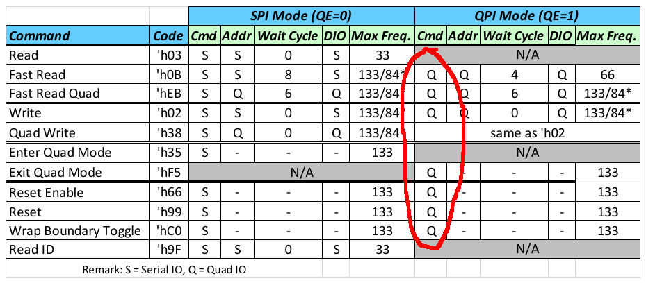
You're absolutelly right! I failled in observing the bus protocol (number of required CLK cycles)...
P.S. My "executioners"...
Got it sorted now but with this PWM smartpin for clocking the smallest write is currently at two consecutive bytes.
PUB  tx_bytes4( paddr, haddr, len ) | m_dat, m_dat2

    m_dat := X_RFBYTE_4P_1DAC4 | (PSRAM_DATA_PINS & $3c)<<17 | X_PINS_ON | X_ALT_ON | len<<1 - 4

    org
                setxfrq ##$8000_0000        ' set sysclock/1 for lead in timing
                rdfast  ##$8000_0000, haddr ' non-blocking FIFO prefetch from haddr (byte granular)
                movbyts paddr, #$1b         ' big-endian
                setbyte paddr, #CMD_WRITE4, #0      ' insert Command into CA word
                drvl    #PSRAM_DATA_PINS    ' active for tx CA phase
                drvl    #PSRAM_CE_PIN

                xinit   ##M_LEADIN, #0      ' lead-in timing, at sysclock/1
                setq    ##($8000_0000 + CLK_DIV>>1) +/ CLK_DIV    ' streamer transfer rate
                xcont   ##M_CA4, paddr      ' tx Command and Address (byte granular address)
                dirh    #PSRAM_CLK_PIN      ' start SPI clock pulses, PWM smartpin

                xcont   m_dat, #0           ' tx data from FIFO
                setword m_dat, #4, #0
                xcont   m_dat, #0           ' tx last four nibbles
                waitxmt                     ' early event so as to allow exact timing on clock cancelling
                waitx   #4 * CLK_DIV - 7 + DAT_REGD - CLK_REGD    ' #1 for sysclk/2, #4..6 for sysclk/3   #7..9 for sysclk/4
                dirl    #PSRAM_CLK_PIN      ' reset smartpin, just the right number of clock pulses
                dirl    #PSRAM_DATA_PINS    ' tristate the databus upon completion
                drvh    #PSRAM_CE_PIN
    end
EDIT: Removed the defunct
cmdparameter and locked it to the one CMD_WRITE4 command.Yeah PWM makes it nasty and you need to fiddle with the timing and you have those extra AUGDs as well... this is how easy it is with PULSE mode in comparison.
wxpin #1, #PSRAM_CLK_PIN ' adjust timing to one P2 clock per update for fast adjustment drvl #PSRAM_CE_PIN ' activate chip select drvl #PSRAM_DATA_PINS ' enable the data bus wxpin divider, #PSRAM_CLK_PIN ' restart pulse mode divider waitx #0 ' delay xinit ximm8, cmdaddr ' send 8 nibbles of address and command via LUT translation wypin wrclks, #PSRAM_CLK_PIN ' start memory clock output xcont xsendimm, hubdata ' send immediate data as nibbles waitxfi ' wait for streamer to end fltl #PSRAM_DATA_PINS ' tri-state DATA bus drvh #PSRAM_CE_PIN ' de-assert chip selectThe AUGs are that way for educational ease ... that and inline Pasm is tricky to have persistent static variables [in register space]. Your driver is full of those.
Inspite any total timing penalty, it's not that bad; even when one needs to add a single new byte to an existing dataset, only the first operation would forcefully need to follow a read-modify-write procedure.
All the forthcoming additions would leverage the fact that copies of the last sequence can be kept under local (to the proccess) memory control, so, despite progressing in pairs, just a single new element would be added, preserving the one that preceeds it (sequentially-addressed-wise).
Can be a good goal/strategy to pursuit, when it'll come to control Hypers and Octos, so as to get some "relief" on the need to keep strict control over DQSM/RWDS during write.
The PWM mode eliminates the hand crafted timing for each clock divider that is absolutely required otherwise ... err, well, I still need to double back and check using
setxfrq ##(($8000_0000+CLK_RATIO>>1) +/ CLK_RATIO)Huh, seems I was mistaken earlier about no data beyond a page. I'm able to set more than a page length for each block of the read/write tester and it correctly copies the random data in and out of the RAM chip every time. Hadn't really tried to now.
8.2 Page Size Page size is 1K (CA[9:0]). Default burst setting is Linear Bursting that crosses page boundary in a continuous manner. Note however that burst operations which cross page boundary have a lower max input clock frequency of 84MHz, and it can cross page boundary one time only in a burst. Optionally the device can also be set to wrap 32 (CA[4:0]) via the Wrap Boundary Toggle command and is not allowed to cross page boundary in this configuration.
8
I know. But what I thought I'd found earlier was a limit to burst length. Turns out I got that one wrong. I was observing only a few extra read clocks at the time. Obviously wasn't enough for proof: https://forums.parallax.com/discussion/comment/1541226/#Comment_1541226
Would you expect anyone to want to clock PSRAMs less than sysclk/4?
Here's my (untested) version of what you had above...it might be optimal in terms of cycles to transfer blocks in nibble mode up to 1kB in size that don't cross the boundary. Is it safe to use the streamer in the middle of an ORG block like this I wonder?
CON SYSCLK_DIV = 2 ' 2,3,4,5 NCO = ($80000000+/SYSCLK_DIV) + (($80000000+//SYSCLK_DIV) ? 1 : 0) DUTY = (((SYSCLK_DIV+1)/2) << 16) + SYSCLK_DIV CMD_WRITE4 = 2 PSRAM_DATA_PINS = 0 + (3<<6) PSRAM_CLK_PIN = 4 PSRAM_CE_PIN = 5 XIMM8 = X_IMM_8X4_4DAC1 | (PSRAM_DATA_PINS & $3c)<<17 | X_PINS_ON | X_ALT_ON | 8 XHUB = X_RFBYTE_4P_1DAC4 | (PSRAM_DATA_PINS & $3c)<<17 | X_PINS_ON PUB tx_bytes4( paddr, haddr, len ) | wrclks org setxfrq ##NCO ' set streamer rate (will this ever change in SPIN2 - maybe just set once) rdfast ##$8000_0000, haddr ' non-blocking FIFO prefetch from haddr (byte granular) shl len, #1 ' convert to nibbles mov wrclks, #8 ' compute clocks for address phase add wrclks, len ' include clocks for data phase add len, ##XHUB ' create streamer command for transferring the length movbyts paddr, #%%0123 ' big-endian setbyte paddr, #CMD_WRITE4, #0 ' insert Command into CA word wxpin #1, #PSRAM_CLK_PIN ' adjust timing to one P2 clock per update for fast adjustment drvl #PSRAM_CE_PIN ' activate chip select drvl #PSRAM_DATA_PINS ' enable the data bus wxpin ##DUTY, #PSRAM_CLK_PIN ' restart pulse mode divider xinit ##XIMM8, paddr ' send 8 nibbles of address and command wypin wrclks, #PSRAM_CLK_PIN ' start memory clock output xcont len, #0 ' send data from HUB waitxfi ' wait for streamer to end fltl #PSRAM_DATA_PINS ' tri-state DATA bus drvh #PSRAM_CE_PIN ' de-assert chip select endEven at 180MHz (Sysclk/2) it would yeld less than ~1400 700 bytes a burst**, per 4-bit device. Not that bad, but still not reaching two full rows...
huh? I'm testing double that length at 4 MHz sysclock.