Yes very nice outcome. I think 4 small rare earth magnet pairs should very easily hold that light screen panel in place. Those magnets are really strong, in fact I use a one inch diameter one to hold a beer cooler (aka stubby holder) to a camping chair frame and that supports a full (not for long ) 375ml/12oz glass bottle - works well. However if you make it too strong you might even find it hard to remove if there is no way to grip the panel from the front side. Might need a push rod from the back or something then, a screen eject button LOL.
@rogloh said:
Yes very nice outcome. I think 4 small rare earth magnet pairs should very easily hold that light screen panel in place. Those magnets are really strong, in fact I use a one inch diameter one to hold a beer cooler (aka stubby holder) to a camping chair frame and that supports a full (not for long ) 375ml/12oz glass bottle - works well. However if you make it too strong you might even find it hard to remove if there is no way to grip the panel from the front side. Might need a push rod from the back or something then, a screen eject button LOL.
I've used 8 x 6mm neodymium magnets, I started off with 10mm but they were WAY too strong. I think I've found a good balance now...
@potatohead said:
Those magnets are plenty strong. If there is any gap between screen cover and cabinet, I would just 3d print a tool to lift the glass up.
Big day today, production of the cabinets has finally started.
I finally managed to get hold of some transfer paper (like masking tape) big enough to cover the plywood I have.
(It took me a while to find some that didn't have any PVC in it, a big nono when it comes to laser cutters)
I need the transfer paper to stop the soot and scorch marks that are a by product of burning through the wood with a laser.
Here you can see scorch and soot marks around the cut edges, they can be sanded or scrubbed off but that seems like a lot of extra work.
And here I have covered the piece in transfer tape before cutting, much better as you can see.
So I cover the whole of one side in the tape, trim as required and then use a brayer to ensure adequate adhesion.
Then I started cutting, this is about a third of the material required for the 8 cabs I am making on this run, the work continues......
@Publison said:
Looks great! This will a good push for the P2.
That's the general idea!
@Cluso99 said:
Looking good Graham!
Personally, I don’t mind the scorch marks as I think it’s part of the design and looks nice.
It's my OCD kicking in, they drive me daft
@cgracey said:
That is great. How about the decals?
I will get a sample done this week with a bit of luck, a friend of mine has a sign making shop so he can print them for me. I'm more worried about how they will stick, I may have to lacquer the panels beforehand.
That's part of the finishing touches so not too concerned right now.
@"Ken Gracey" said:
What are the Parallax parts needed for the P2ARC8DE?
Displays? How about these boards?
Ken Gracey
Yes, those boards are fine but the PCB on the left is more for a standalone version connected to a display and audio amp rather than what we will use in the cabinets.
A P2 Edge is also needed of course and for displays I have allowed for the same size as your 7" LCD display, the design can handle various thickness types.
I have two different types that work well, the only mod I had to make to the Parallax supplied LCD was to remove the driver PCB that is stuck onto the rear so it can be mounted on a frame.
I've cut out all of the parts required to start building but before I do I wanted to sort out what we are doing with the two side panels and the joystick area.
We thought it would be neat to put a vinyl print on these faces but the reality is that self adhesive vinyl needs a non porous and shiny surface to adhere to.
I've spent most of my time this week on different finishes, testing lacquer and varnish for which is best.
Well the answer is spray lacquer gives by far the best results but comes at a cost, the labour element to spray, sand, spray, sand etc.. is too high.
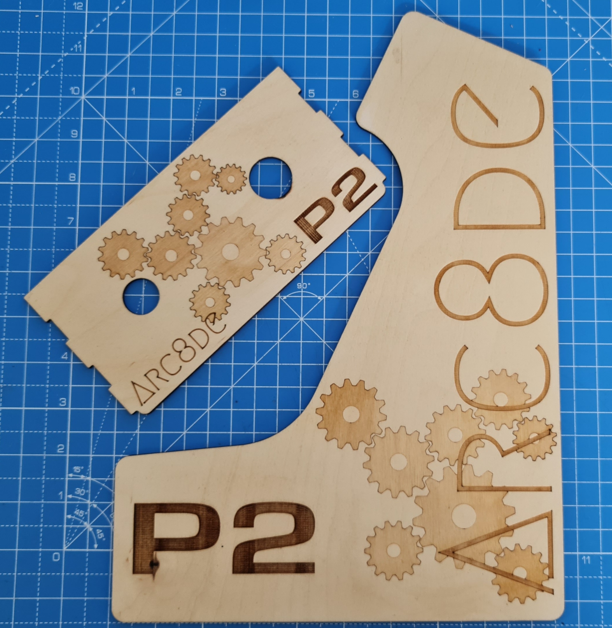
That made me rethink the whole vinyl print idea and instead I have redrawn the graphics in CAD and engraved them onto the side panel and joystick area.
What do you think?
Looks great @coley!
To keep the cost down right now, I would stick to the laser engraving right now.
If you can post the vinyl file, users can print their own later on.
Hi,
As you asked for feedback.
This is impressing work!
Beeing a mechanics engineer I cannot avoid to say, that such pictures of gears make feel me very sick, because these will never work. Meshing gears have to have the same module, which describes the size of the teeth. If you turn one wheel, the next tooth of this wheel has to fit into the next clearance between teeth of the other wheel.
Of course only a problem for some people...
Christof
The guy who did the design isn't a mechanical engineer, and so didn't think that by scaling the image, to make more he'd also have to scale the teeth to compensate the difference in speed moving around the wheel.
@"Christof Eb." said:
Hi,
As you asked for feedback.
This is impressing work!
Beeing a mechanics engineer I cannot avoid to say, that such pictures of gears make feel me very sick, because these will never work. Meshing gears have to have the same module, which describes the size of the teeth. If you turn one wheel, the next tooth of this wheel has to fit into the next clearance between teeth of the other wheel.
Of course only a problem for some people...
Christof


Comments
Look great, Coley!
Looks great!
Yes very nice outcome. I think 4 small rare earth magnet pairs should very easily hold that light screen panel in place. Those magnets are really strong, in fact I use a one inch diameter one to hold a beer cooler (aka stubby holder) to a camping chair frame and that supports a full (not for long ) 375ml/12oz glass bottle - works well. However if you make it too strong you might even find it hard to remove if there is no way to grip the panel from the front side. Might need a push rod from the back or something then, a screen eject button LOL.
Those magnets are plenty strong. If there is any gap between screen cover and cabinet, I would just 3d print a tool to lift the glass up.
Cheers guys, nearly there now!
I've used 8 x 6mm neodymium magnets, I started off with 10mm but they were WAY too strong. I think I've found a good balance now...
There are no gaps, it's a push out from the back")
No worries. The whole thing is not big. Easy to do.
Big day today, production of the cabinets has finally started.
I finally managed to get hold of some transfer paper (like masking tape) big enough to cover the plywood I have.
(It took me a while to find some that didn't have any PVC in it, a big nono when it comes to laser cutters)
I need the transfer paper to stop the soot and scorch marks that are a by product of burning through the wood with a laser.
Here you can see scorch and soot marks around the cut edges, they can be sanded or scrubbed off but that seems like a lot of extra work.
And here I have covered the piece in transfer tape before cutting, much better as you can see.
So I cover the whole of one side in the tape, trim as required and then use a brayer to ensure adequate adhesion.
Then I started cutting, this is about a third of the material required for the 8 cabs I am making on this run, the work continues......
Looks great! This will a good push for the P2.
Looking good Graham!
Personally, I don’t mind the scorch marks as I think it’s part of the design and looks nice.
That is great. How about the decals?
That's the general idea!
It's my OCD kicking in, they drive me daft")
I will get a sample done this week with a bit of luck, a friend of mine has a sign making shop so he can print them for me. I'm more worried about how they will stick, I may have to lacquer the panels beforehand.
That's part of the finishing touches so not too concerned right now.
What are the Parallax parts needed for the P2ARC8DE?
Displays? How about these boards?
Ken Gracey
Yes, those boards are fine but the PCB on the left is more for a standalone version connected to a display and audio amp rather than what we will use in the cabinets.
A P2 Edge is also needed of course and for displays I have allowed for the same size as your 7" LCD display, the design can handle various thickness types.
I have two different types that work well, the only mod I had to make to the Parallax supplied LCD was to remove the driver PCB that is stuck onto the rear so it can be mounted on a frame.
It's been a very busy week but managed to get some more time on the laser.")
Much better now I've added a chiller unit so I can cut for longer periods
Great Output! Thanks for pushing forward.
Thank you, I wish I had more time to spend on this but at least it's inching forward.
I've cut out all of the parts required to start building but before I do I wanted to sort out what we are doing with the two side panels and the joystick area.
We thought it would be neat to put a vinyl print on these faces but the reality is that self adhesive vinyl needs a non porous and shiny surface to adhere to.
I've spent most of my time this week on different finishes, testing lacquer and varnish for which is best.
Well the answer is spray lacquer gives by far the best results but comes at a cost, the labour element to spray, sand, spray, sand etc.. is too high.
That made me rethink the whole vinyl print idea and instead I have redrawn the graphics in CAD and engraved them onto the side panel and joystick area.
What do you think?
Looks great @coley!
To keep the cost down right now, I would stick to the laser engraving right now.
If you can post the vinyl file, users can print their own later on.
I wondered about that Coley
First, I love the engraving. Always thought it was a killer look, and those can be painted.
Second, others could make it out of polycarb, or other materials and the vinyl will stick.
Love it!
Always thought the burn marks that you get from the laser cut ply looks good and the laser decal adds to this look.
Looks great Coley
What thickness ply are you using?
Thanks all.
3mm Birch Ply, it's really easy to work with, nice and stable.
I will also be making some out of 3mm clear/smoked Acrylic when time permits...
I love this project!
Have you run Phoenix on it yet?!
😁 Not yet but I definitely will, great work on the sounds by the way!
I can't wait for it to be ready to run Phoenix on it!
Almost there
Hi,
As you asked for feedback.
This is impressing work!
Beeing a mechanics engineer I cannot avoid to say, that such pictures of gears make feel me very sick, because these will never work. Meshing gears have to have the same module, which describes the size of the teeth. If you turn one wheel, the next tooth of this wheel has to fit into the next clearance between teeth of the other wheel.
Of course only a problem for some people...
Christof
Very true and well spotted.
The guy who did the design isn't a mechanical engineer, and so didn't think that by scaling the image, to make more he'd also have to scale the teeth to compensate the difference in speed moving around the wheel.
Thanks Christof.
I knew it would 'grind your gears'")
I didn't realise there were so many component parts....