@evanh said:
The only way to use a SD card, and not be constantly removing it, and also develop new code via serial booting is to have a loader in the EEPROM. Thereby entirely bypassing the ROM's SD boot solution.
I usually just set the pullup for the long serial window. Forget which one that was. That will never auto-boot anything, but that's usually desireable.
P59 pull-up forces serial only booting. P59 pull-down forces no serial booting.
Yeah, I suppose that is an option: Boot from serial as a loader until happy with finished product, then put the loader on the SD card and make it bootable.
You do know that's a work-around, right? It overpowers the incorrectly wired R24 pull-down on P58 that should be a pull-up. I expect you to correct the schematic and fix the already made modules in the medium term.
PS: The only reason, I think, that FSRW works for you is because you're using the broken sdspi_bashed2.spin2 driver that doesn't ever do a card busy check. Which is also why FSRW needs multiple attempts to get anything done.
The fact that the Eval and Edge boards have no pull-up resistor present on P58 means you can remove the Swap's R24 and be reasonably confident of future drivers always handling it.
Pull-ups on the LEDs don't matter but I have no idea what the PGOODx pins will do from that regulator. One hopes they go hi-Z when good. My gut reaction is cut those tracks so that P58/P59 no longer reach the regulator chip.
I'd ditch both the LEDs and change the PGLED1/PGLED2 module pins into extra GND pins. If you want power indicator LEDs then they can go on the carrier board.
EDIT: Actually, the biggest design improvement would be to remove the P46..P56 HyperRAM signals from the module's pinout. That then frees up eleven module pins to be made into GND contacts.
Ok, removed R24 from 14 of the completed modules that were packaged up to go.
Also, updated the flash.
Thanks @evanh for your help with this. Good to have this change made now as they are going on sale today.
Hopefully, remember to do this for the other ones still in production.
Just making the test with shell.c, as was done for these, will catch an mistakes.
@Rayman said:
@evanh There's a pin that disables the HyperRam, allowing use of these pins for something else.
I'd remove all those tinylogic chips too. Go back to the dip switches, or use bridgeable pads. Do the EdgeCard way of having two models. One model with added RAM and one without.
Finishing some more SWaP modules and ran out of 10k 0402 resistors
Very frustrating that something so cheap can mess this up...
Just ordered 1000 or more each of all the resistors needed.
Also, 100+ of all the caps and other tiny parts.
This should help keep production on schedule...
Finished 5 new SWaP modules today. One of them seems to have a bad HyperRam interface though...
Hard to diagnose without a simple code to read something like the chip ID.
I have such a code, but it is very ancient, before Spin2 and such...
Trying to polish it up now so can figure out if it's a bad bit or something else...
Rayman,
I've added the hyperRAM object from the same era as the QPI object in the other EC32MB topic. I would've added it some hours ago but my revA Stamp/Swap module was randomly giving 1% memory errors that I thought must have been a timing issue in the software. Turns out it must have been some dirt, presumably metallic, on the module. After some blowing and a re-socket it came right. The Prop2 pins are like a fine mesh, they'll collect anything.
There is two top level programs - The tester and the calibrator.
PS: I've added the QPI object here too. All in one place now.


Comments
P59 pull-up forces serial only booting. P59 pull-down forces no serial booting.
Yeah, I suppose that is an option: Boot from serial as a loader until happy with finished product, then put the loader on the SD card and make it bootable.
@evanh Looks like that was it...
FatFS works from boot with this change to line 550 in sdmm.cc:
//spm_rx |= P_SYNC_RX | P_OE | P_INVERT_OUTPUT | P_HIGH_15K | P_LOW_15K; // rx smartpin mode, with 15 k pull-up spm_rx |= P_SYNC_RX | P_OE | P_INVERT_OUTPUT | P_HIGH_1MA | P_LOW_FLOAT; // pull-upYou do know that's a work-around, right? It overpowers the incorrectly wired R24 pull-down on P58 that should be a pull-up. I expect you to correct the schematic and fix the already made modules in the medium term.
PS: The only reason, I think, that FSRW works for you is because you're using the broken sdspi_bashed2.spin2 driver that doesn't ever do a card busy check. Which is also why FSRW needs multiple attempts to get anything done.
@evanh what’s wrong with the work around?
Not sure how changing the pulldown would affect other parts sharing that pin…
It ain't gonna be standard issue for a starters. It'll be up to you to add the workaround each time there is an update to
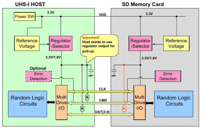
includes.The pull-down is a mistake. A tad surprisingly, the Parallax board have no resistor at all. So my programmed pull-up is actually needed.
Everything except the CLK requires a pull-up.
The fact that the Eval and Edge boards have no pull-up resistor present on P58 means you can remove the Swap's R24 and be reasonably confident of future drivers always handling it.
@evanh Have to see how that would affect the behavior of the PowerGood1 LED...
Pull-ups on the LEDs don't matter but I have no idea what the PGOODx pins will do from that regulator. One hopes they go hi-Z when good. My gut reaction is cut those tracks so that P58/P59 no longer reach the regulator chip.
@evanh Don't think I'll be cutting any traces..
R24 is in an easy place to remove though. I'll try that.
Goes without saying that future board production runs should be changed to fix these issues.
Removing R24 seems to make FatFS happy. But, it turns off the associated LED that was kind of using as power LED.
Tried flashing this to get it back:
But, this seems to have the effect of erasing the uSD. So, not doing that...
I'd ditch both the LEDs and change the PGLED1/PGLED2 module pins into extra GND pins. If you want power indicator LEDs then they can go on the carrier board.
EDIT: Actually, the biggest design improvement would be to remove the P46..P56 HyperRAM signals from the module's pinout. That then frees up eleven module pins to be made into GND contacts.
@evanh There's a pin that disables the HyperRam, allowing use of these pins for something else.
Flashing with a program the lights the P59 LED doesn't seem to break anything.
This might be the new default flash for these units:
Ok, removed R24 from 14 of the completed modules that were packaged up to go.
Also, updated the flash.
Thanks @evanh for your help with this. Good to have this change made now as they are going on sale today.
Hopefully, remember to do this for the other ones still in production.
Just making the test with shell.c, as was done for these, will catch an mistakes.
I'd remove all those tinylogic chips too. Go back to the dip switches, or use bridgeable pads. Do the EdgeCard way of having two models. One model with added RAM and one without.
Has the mythical 512MBit (=64MB) HyperRAM been tried by anyone yet?
Maybe something for next run.
Not a fan of dip switches…
Think SWaP module is just about perfect now.
The nice thing with bridgeable pads is they don't have any assembly so can easily be on the underside of the PCB.
Finishing some more SWaP modules and ran out of 10k 0402 resistors
Very frustrating that something so cheap can mess this up...
Just ordered 1000 or more each of all the resistors needed.
Also, 100+ of all the caps and other tiny parts.
This should help keep production on schedule...
Think the problem was trying to use the PandaPlacer's feeders to do 0402 parts. It just doesn't work for me. Lost a lot of parts...
But, the strip feeders work great. Should be all good now... Just a learning curve...
Haven't thought it through, but appears SWaP module PLCC-84 socket can fit reasonably well onto an Arduino Mega type board...
Finished 5 new SWaP modules today. One of them seems to have a bad HyperRam interface though...
Hard to diagnose without a simple code to read something like the chip ID.
I have such a code, but it is very ancient, before Spin2 and such...
Trying to polish it up now so can figure out if it's a bad bit or something else...
Rayman,
I've added the hyperRAM object from the same era as the QPI object in the other EC32MB topic. I would've added it some hours ago but my revA Stamp/Swap module was randomly giving 1% memory errors that I thought must have been a timing issue in the software. Turns out it must have been some dirt, presumably metallic, on the module. After some blowing and a re-socket it came right. The Prop2 pins are like a fine mesh, they'll collect anything.
There is two top level programs - The tester and the calibrator.")
PS: I've added the QPI object here too. All in one place now.