Instrumentation - I need a word that means GND-VIO-registered.
Internally referenced?
My first attempt at precise ADC with air quality detectors probably suffered from having VIO on a switched mode power supply.
I can see now that that was definitely a bad idea... Have to try again with pins on LDO regulator...
Presumably the LDO is not sensitive to temperature, but probably need to check that...
Now I'm wondering if there'd be any benefit at all to using one pin with an external reference...
Maybe an external reference would be more stable than VIO?
But, the results shown above look very impressive, so perhaps that'd be overkill...
@evanh said:
Huh, Chip, this problem seems to have gone away on me - https://forums.parallax.com/discussion/comment/1552065/#Comment_1552065
Given you're now happily using exactly what I'd complained about I'm now guessing I was triggering a Flexspin compiler bug back then. I'm now using a newer version of Flexspin, and presumably you never struck any such problem using Pnut in the interim?
Yes, when you do the WXPIN, the four LSBs set a frame time of power(2, D.[3..0]) clocks.
@TonyB_ said:
On a related ADC matter, I've been thinking about scope data. Oversampling could be done with the down ramp of the previous Hann/Tukey window coinciding exactly with the up ramp of the next one. If overlap is perfect then all ADC bits will have equal weight. For Hann window I think successive samples must be taken every 15 cycles. If four samples were done then the window would look like a 70-tap Tukey. Whether the results would be better than the inbuilt 68-tap Tukey I don't know.
How would we control the up and down ramp, since the bits flow through the window at the same time? The filter stays still and the data stream goes through it. We would have to stall the data stream, then?
But a particular ADC bit takes a certain time to pass through and the time between oversamples must be less than this propagation time. Either it will work or I'm talking nonsense.
I can't picture how it would work.
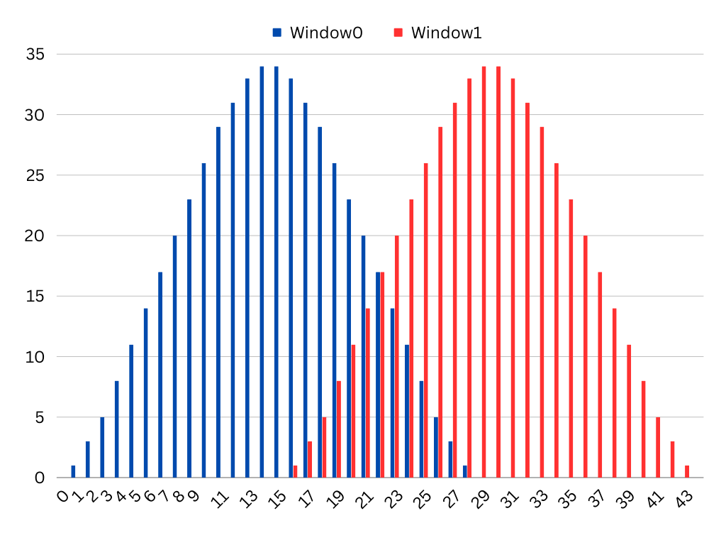
Here are two 28-tap Hann windows overlapped:
X-axis shows time in cycles. Values for the two windows sum to the max value where they overlap. The next GETSCP must be executed exactly 15 or 30 or 51 cycles after the previous one for 22-tap Hann or 45-tap Tukey or 68-tap Tukey, respectively.
@TonyB_ said:
On a related ADC matter, I've been thinking about scope data. Oversampling could be done with the down ramp of the previous Hann/Tukey window coinciding exactly with the up ramp of the next one. If overlap is perfect then all ADC bits will have equal weight. For Hann window I think successive samples must be taken every 15 cycles. If four samples were done then the window would look like a 70-tap Tukey. Whether the results would be better than the inbuilt 68-tap Tukey I don't know.
How would we control the up and down ramp, since the bits flow through the window at the same time? The filter stays still and the data stream goes through it. We would have to stall the data stream, then?
But a particular ADC bit takes a certain time to pass through and the time between oversamples must be less than this propagation time. Either it will work or I'm talking nonsense.
I can't picture how it would work.
Here are two 28-tap Hann windows overlapped:
X-axis shows time in cycles. Values for the two windows sum to the max value where they overlap. The next GETSCP must be executed exactly 15 or 30 or 51 cycles after the previous one for 22-tap Hann or 45-tap Tukey or 68-tap Tukey, respectively.
Can you explain what the objective is, again? There's something I am not understanding. You are not thinking about a delayed bit stream going into one pin, while the other pin gets the live stream, right?
I think Tony is just talking about how often decimations occur. I've not tried to understand what that hardware is doing so have tried not to butted in here.
@cgracey Ok, just downloaded the code and about the first thing I see is this:
con _clkfreq = 320_000_000
So, this seems very odd to me. All the Parallax docs say 300 MHz is max for P2, so this is what I'd call the "overclocked" realm.
Does it work at a lower clock frequency or is 320 MHz required?
@TonyB_ said:
On a related ADC matter, I've been thinking about scope data. Oversampling could be done with the down ramp of the previous Hann/Tukey window coinciding exactly with the up ramp of the next one. If overlap is perfect then all ADC bits will have equal weight. For Hann window I think successive samples must be taken every 15 cycles. If four samples were done then the window would look like a 70-tap Tukey. Whether the results would be better than the inbuilt 68-tap Tukey I don't know.
How would we control the up and down ramp, since the bits flow through the window at the same time? The filter stays still and the data stream goes through it. We would have to stall the data stream, then?
But a particular ADC bit takes a certain time to pass through and the time between oversamples must be less than this propagation time. Either it will work or I'm talking nonsense.
I can't picture how it would work.
Here are two 28-tap Hann windows overlapped:
X-axis shows time in cycles. Values for the two windows sum to the max value where they overlap. The next GETSCP must be executed exactly 15 or 30 or 51 cycles after the previous one for 22-tap Hann or 45-tap Tukey or 68-tap Tukey, respectively.
Can you explain what the objective is, again? There's something I am not understanding. You are not thinking about a delayed bit stream going into one pin, while the other pin gets the live stream, right?
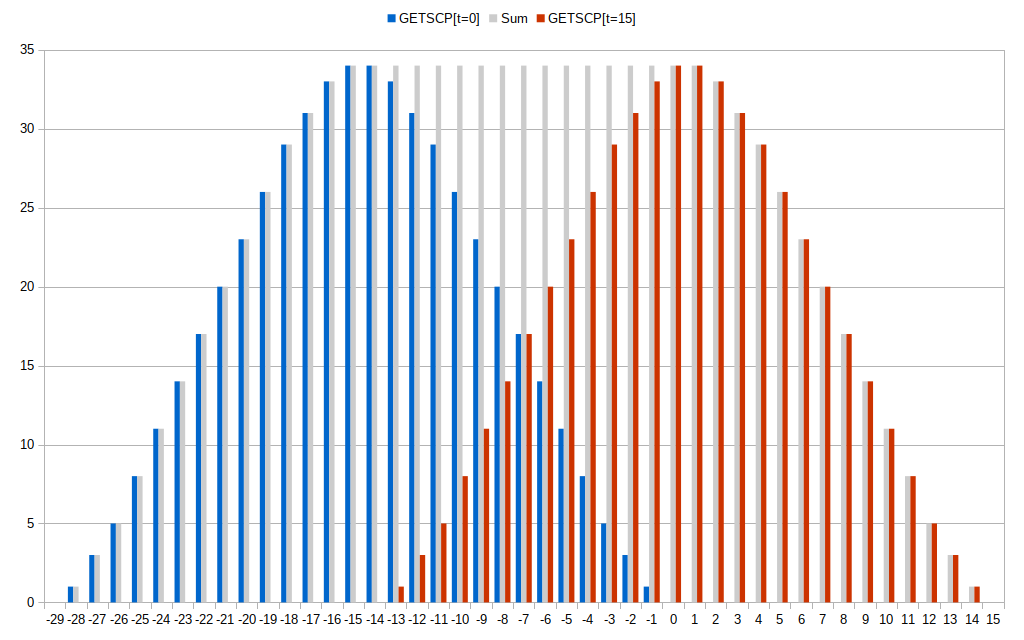
Chip, this is about GETSCP and how to increase ENOB by oversampling. ADC-related so I thought it was worth mentioning here. The idea is to increase the length of the contiguous bitstream by overlapping the Hann and Tukey windows in a precise way. This converts the Hann into a Tukey by creating a plateau and extends the plateaus for the Tukeys.
For example, in the chart shown above for the Hann a GETSCP at t = 0 and another at t = 15 cycles increases the bitstream length from 28 to 43 with a plateau 17 bits long, 13 of which result from summing the red and blue overlap. In effect, a 43-tap Tukey has been created by precise 2X oversampling. Theoretically 2X increases the EONB by 0.5 and 4X by 1. If four GETSCP's were done for the 68-tap Tukey at t = 0, 51, 102 and 153 cycles then the bitstream length would be 51 x 3 + 68 = 221 which should be enough for EONB = 7.
(The 28-tap Hann has a don't care config bit. Perhaps this could be used in the future for 8 pins x 4-bit scope data. I doubt the Hann ENOB is much more than 4.)
@Rayman said:
@cgracey Ok, just downloaded the code and about the first thing I see is this:
con _clkfreq = 320_000_000
So, this seems very odd to me. All the Parallax docs say 300 MHz is max for P2, so this is what I'd call the "overclocked" realm.
Does it work at a lower clock frequency or is 320 MHz required?
It works at any frequency >= 10MHz. I just like to go fast.
@TonyB_ said:
On a related ADC matter, I've been thinking about scope data. Oversampling could be done with the down ramp of the previous Hann/Tukey window coinciding exactly with the up ramp of the next one. If overlap is perfect then all ADC bits will have equal weight. For Hann window I think successive samples must be taken every 15 cycles. If four samples were done then the window would look like a 70-tap Tukey. Whether the results would be better than the inbuilt 68-tap Tukey I don't know.
How would we control the up and down ramp, since the bits flow through the window at the same time? The filter stays still and the data stream goes through it. We would have to stall the data stream, then?
But a particular ADC bit takes a certain time to pass through and the time between oversamples must be less than this propagation time. Either it will work or I'm talking nonsense.
I can't picture how it would work.
Here are two 28-tap Hann windows overlapped:
X-axis shows time in cycles. Values for the two windows sum to the max value where they overlap. The next GETSCP must be executed exactly 15 or 30 or 51 cycles after the previous one for 22-tap Hann or 45-tap Tukey or 68-tap Tukey, respectively.
Can you explain what the objective is, again? There's something I am not understanding. You are not thinking about a delayed bit stream going into one pin, while the other pin gets the live stream, right?
Chip, this is about GETSCP and how to increase ENOB by oversampling. ADC-related so I thought it was worth mentioning here. The idea is to increase the length of the contiguous bitstream by overlapping the Hann and Tukey windows in a precise way. This converts the Hann into a Tukey by creating a plateau and extends the plateaus for the Tukeys.
For example, in the chart shown above for the Hann a GETSCP at t = 0 and another at t = 15 cycles increases the bitstream length from 28 to 43 with a plateau 17 bits long, 13 of which result from summing the red and blue overlap. In effect, a 43-tap Tukey has been created by precise 2X oversampling. Theoretically 2X increases the EONB by 0.5 and 4X by 1. If four GETSCP's were done for the 68-tap Tukey at t = 0, 51, 102 and 153 cycles then the bitstream length would be 51 x 3 + 68 = 221 which should be enough for EONB = 7.
(The 28-tap Hann has a don't care config bit. Perhaps this could be used in the future for 8 pins x 4-bit scope data. I doubt the Hann ENOB is much more than 4.)
Okay. I think I see what you are saying. I need to think about it more. That's a pretty clever way to get more resolution. I wonder how far it can be taken? What the scope modes give is very high phase resolution, but it would be good to increase ENOB, too.
I found a better way to do the sample computation.
Here is what I had yesterday:
ComputeSample   mov     pa,Vio                  'compute (Vio - Gio)
                sub     pa,Gio
                encod   shift,pa                'msb justify
                subr    shift,#31
                shl     pa,shift
                qfrac   ##3_300_000<<9,pa       'compute (3_300_000 / (Vio - Gio)) to 32-bit precision
                getqx   pb
                mov     pa,Sig                  'compute (Sig - Gio)
                sub     pa,Gio          wc
        if_c    neg     pa                      'if negative, make positive for QMUL
                qmul    pa,pb                   'compute (Sig - Gio) * (3_300_000 / (Vio - Gio))
                getqx   pa
                getqy   pb
        if_c    not     pa                      'negate product? NOT is sufficient
        if_c    not     pb
                subr    shift,#9        wcz     'determine shift needed, if any
  if_nz_and_nc  sar     pb,shift                'shift right?
  if_nz_and_c   shr     pa,shift                'shift left?
  if_nz_and_c   subr    shift,#32
  if_nz_and_c   shl     pb,shift
  if_nz_and_c   or      pb,pa
        _ret_   mov     sample,pb
I spent a lot of effort and code maximizing the math precision above, but I found a better way. Rather than pre- and post-shift values, let the CORDIC divider handle the scaling automatically. I rearranged the equation so that you just compute (Sig-Gio)/(Vio-Gio) using QFRAC to give you a 32-bit-quality ratio which can then be scaled to 3_300_000 uV:
ComputeSample   mov     pa,Sig                  'compute ABS(Sig - Gio)
                sub     pa,Gio
                abs     pa              wc
                mov     pb,Vio                  'compute (Vio - Gio) << 1   (<< 1 allows Sig > Vio for QFRAC)
                sub     pb,Gio
                shl     pb,#1
                qfrac   pa,pb                   'compute r = (ABS(Sig - Gio) << 32) / ((Vio - Gio)  << 1)
                getqx   pa
                qmul    pa,##3_300_000<<1       'compute (r * (3_300_000 << 1)) >> 32
                getqy   pa
        if_c    neg     pa                      'need to negate result?
        _ret_   mov     sample,pa
I've made the 3-pin ADC work at exactly 60Hz to filter out AC noise that is all around.
It can now resolve 100uV p-p signals:
Here is the noise floor:
Here is the noise floor without averaging:
I thought I'd use the FFT debug display to see if there is any pattern to this noise:
Since these spikes are at power-of-two sample intervals, I believe they are due to finite numerical values of raw sub-samples being over-summed within each final sample. I think their prominence creates digital artifacts at these conspicuous intervals.
I am wondering if noise can be used to dither the sub-samples in some way to make them noisier in the short term, but more informational, on average.
Well, I've injected electrical noise by enabling the 4th pin (which shares the on-chip power bus) as a DAC noise output. That didn't do much, but shifted the DC level because of the internal power draw. Then, I coupled that noise pin to the ADC pins via resistor and then capacitor, and it made things noisier, but the FFT remained the same.
I am pretty much convinced that the problem is there's not a continuous range of sub-sample conversion values, but sparse discrete values which come up over and over again, undermining the summing process. I am not sure how to get around this. I did try dithering the sample period by one to several clocks and the SINC2 filter absolutely hates that. It goes crazy and outputs wild values. I might try using highs-counting mode, foregoing the SINC2 filter, but my experience with that has been poor, so far. I know I could randomly dither the sampling time that way without blowing things up. I'll try that.
I changed it to highs-counting mode (%01111) and it's worse, as I expected, but I dithered the sample time to mix things up a bit. That just made things even worse and didn't change the FFT, at all.
Now, I've substituted range-bound random numbers for the final samples and the FFT is still the same! So, I now think the FFT is the way it is because it is fed with a narrow band of numbers (the samples), maybe varying by 50 p-p, and these intervals are always going to occur in the same proportions because of the limited range of values. To be sure, I jacked the numerical range up to 64k and those FFT peaks disappeared down into the noise. So, these FFT peaks are due to the samples occuring within a small range of random integer values. There is nothing deeper going on to explain the FFT pattern.
So, I'm not thinking we have numerical sparseness in the sub-samples, anymore. Maybe we are just at an impassable noise floor for the ADC. I will still think more about this, though, because there may be some other way to improve it, yet.
Chip,
I think that being able to do an EKG sounds very interesting and cool! especially if you don't need any special circuitry.
I was wondering if something like this was possible, I have Afib and would like to make something to monitor my heart rate.
@HydraHacker said:
Chip,
I think that being able to do an EKG sounds very interesting and cool! especially if you don't need any special circuitry.
I was wondering if something like this was possible, I have Afib and would like to make something to monitor my heart rate.
HydraHacker
I will see today if I can read anything from my skin.
Here's a bar chart of two overlapped Hann windows with x-axis starting at time t = -29 cycles.
Each division on the X-axis represents a clock cycle and a unique 1-bit ADC value. A GETSCP is executed at time t = 0 (shown in blue). The Hann shift register is 30 bits long but the oldest and newest ADC bits have tap co-efficients of zero so that only 28 bits contribute to the byte result. Another GETSCP is executed at t = 15 (red). As 15 < 28 some bits contribute to both GETSCP results and these are the ones that overlap in the chart. E.g. if set the t = -13 bit adds 33 and 1 which sum to the maximum co-efficient of 34, as do all the overlapped bits thus creating a plateau. If N GETSCPs are overlapped sum the byte values and divide them by N. Execute GETSCP every 15 or 30 or 51 cycles for 28-tap Hann or 45-tap Tukey or 68-tap Tukey, respectively.
@TonyB_ said:
Here's a bar chart of two overlapped Hann windows with x-axis starting at time t = -29 cycles.
Each division on the X-axis represents a clock cycle and a unique 1-bit ADC value. A GETSCP is executed at time t = 0 (shown in blue). The Hann shift register is 30 bits long but the oldest and newest ADC bits have tap co-efficients of zero so that only 28 bits contribute to the byte result. Another GETSCP is executed at t = 15 (red). As 15 < 28 some bits contribute to both GETSCP results and these are the ones that overlap in the chart. E.g. if set the t = -13 bit adds 33 and 1 which sum to the maximum co-efficient of 34, as do all the overlapped bits thus creating a plateau. If N GETSCPs are overlapped sum the byte values and divide them by N. Execute GETSCP every 15 or 30 or 51 cycles for 28-tap Hann or 45-tap Tukey or 68-tap Tukey, respectively.
I finally get it!
The sum of the red and the blue (shown by gray lines) can create a sustained filter if polled at exact intervals.
I set up a spreadsheet to look at Gio and Vio readings, along with Float readings (the ADC can be switched to floating input). Float readings are within 0.5% of being half-way between Gio and Vio readings.
My hope was that instead of reading both Gio and Vio, in addition to the external pin, I could just read Float and the external pin and make things more efficient. The trouble is that it doesn't keep things very tight. In my experiments, I'm seeing about 1000uV of noise, which is a lot worse than the 50uV I can get by measuring Gio, Vio, and the external pin. I was really hoping this would allow a shortcut, but it doesn't work nearly well enough. There's no substitute for reading all three: Gio, Vio, and the external pin.
One thing I noticed is that GIO and VIO are fairly well correlated. If GIO is higher than average for a particular pin, chances are that its VIO is higher too. It seemed like that span (VIO-GIO) was more consistent than individual GIO or VIO values. So, knowing either one well, and applying expectations/calculations to the other, might be "almost as good" as spending more time to study both.
In our testing VIO was more stable than GIO, so it may work better to lean more heavily on the VIO reading and established span, than VIO and GIO.
Also, during our testing we switched from spending equal time on GIO-Ext Pin-VIO, to GIO-ExtPin-VIO-ExtPin...
The other thing to note is that some pins are more stable wrt temperature than others. Whether this also applies to your noise amount, I don't know but it would be good to find out. The general rule is that pins whose GIO and VIO are closer to 'average' (across all pins) tend to be more stable. Pins that have GIO and VIO that are more 'outliers' tend to have larger excursions. You can see this as longer excursions in the lower left corner of the following graph courtesy of evanh
Each of those trails represents how one pins VIO and GIO move with respect to temperature (in turn generated by frequency stepping from 80 to 320 MHz or so). You can see how the outlier pins with lower or higher VIO/GIO pairings tend to have a large excursion as the chip was heated and cooled due to changing frequency.
I haven't repeated this on a second IC, so I don't know whether these characteristics are typical across ICs, or not. If its different on different ICs, then we have some kind of unique ID, i guess.
One thing I've wondered is whether we could generate heat within each pin pad, by (eg) outputting a 75 ohm dac to mid level. If that technique self-heats enough, then it might be possible to build a model for how each pin behaves, and apply that to improve accuracy. Is there another way to self-heat you can think of?
With the noise you're seeing, how much is contributed from the GIO and VIO and calculations, vs the pin measurement itself? If you hold GIO and VIO constant for a while, as well as the pin input to a constant level (eg 1.5v battery), is the noise half? quarter? three quarters?
@Tubular said:
I haven't repeated this on a second IC, so I don't know whether these characteristics are typical across ICs, or not. If its different on different ICs, then we have some kind of unique ID, i guess.
I never tried replicating that on any of my chips either.
I can't see it helping instrumentation but it might show up some commonalities. Or, alternately, as you say, produce a repeatable unique ID.
One thing I've wondered is whether we could generate heat within each pin pad, by (eg) outputting a 75 ohm dac to mid level. If that technique self-heats enough, then it might be possible to build a model for how each pin behaves, and apply that to improve accuracy. Is there another way to self-heat you can think of?
Need to work out how varied the behaviour is under test first. Decide on a useful direction before hunting for ways to get there.
@Tubular said:
One thing I noticed is that GIO and VIO are fairly well correlated. If GIO is higher than average for a particular pin, chances are that its VIO is higher too. It seemed like that span (VIO-GIO) was more consistent than individual GIO or VIO values. So, knowing either one well, and applying expectations/calculations to the other, might be "almost as good" as spending more time to study both.
In our testing VIO was more stable than GIO, so it may work better to lean more heavily on the VIO reading and established span, than VIO and GIO.
Also, during our testing we switched from spending equal time on GIO-Ext Pin-VIO, to GIO-ExtPin-VIO-ExtPin...
The other thing to note is that some pins are more stable wrt temperature than others. Whether this also applies to your noise amount, I don't know but it would be good to find out. The general rule is that pins whose GIO and VIO are closer to 'average' (across all pins) tend to be more stable. Pins that have GIO and VIO that are more 'outliers' tend to have larger excursions. You can see this as longer excursions in the lower left corner of the following graph courtesy of evanh
Each of those trails represents how one pins VIO and GIO move with respect to temperature (in turn generated by frequency stepping from 80 to 320 MHz or so). You can see how the outlier pins with lower or higher VIO/GIO pairings tend to have a large excursion as the chip was heated and cooled due to changing frequency.
I haven't repeated this on a second IC, so I don't know whether these characteristics are typical across ICs, or not. If its different on different ICs, then we have some kind of unique ID, i guess.
One thing I've wondered is whether we could generate heat within each pin pad, by (eg) outputting a 75 ohm dac to mid level. If that technique self-heats enough, then it might be possible to build a model for how each pin behaves, and apply that to improve accuracy. Is there another way to self-heat you can think of?
With the noise you're seeing, how much is contributed from the GIO and VIO and calculations, vs the pin measurement itself? If you hold GIO and VIO constant for a while, as well as the pin input to a constant level (eg 1.5v battery), is the noise half? quarter? three quarters?
It's been my experience that all three need routine measurement: VIO, GIO, and the pin.
I was doing what you were talking about above, where you measure:
VIO
pin
GIO
pin
VIO
pin
GIO
pin
(etc)
This way, you can output a sample after every GIO and VIO measurement, because you have a fresh history of either GIO,pin,VIO or VIO,pin,GIO. You get to use each VIO and GIO measurement twice.
You can then use a second pin to interleave its measurements with the first pin's measurements:
This way, on each cycle you are measuring one of the tied-together pins, which keeps the impedance constant for the analog source.
One way I found to correlate the two overall (GIO,VIO,pin) measurements in this dual-pin approach was to average the last two computed samples together. This cuts the Nyquist performance, but gets the pins working together.
Another way to do it might be to take the last four double measurements after each discrete set and separately sum the two GIOs << 1, the two VIOs << 1, and all four pin measurements, then do the math to produce a sample. That would further erode the Nyquist performance, though.
I do appreciate very much, that we shall have some sort of receipt for improved ADC performance, because I had to replace sigma delta ADC with a method that uses the 8 bit DAC and comparator and which gave better performance! Performance was also inconsistent between two builds before.
It is necessary to have a definition for "ENOB". I strongly suggest to use ENOB= log2( 3.3V/Std(measurements) ). Std = standard deviation. https://en.wikipedia.org/wiki/Standard_deviation. The reason to use this, is that the standard deviation is a very commonly used tool to evaluate data of measurements and it's formula is the same as RMS, only it takes into account an average other than zero. Of course, ENOB cannot be better than resolution.
When we consider, that most sensors will have an output impedance in the order of magnitude of 2k and the sigma delta ADC has an input impedance of 450k then it is clear, that precision will be limited. If we compare P2 with other microcontrollers than we see, that 10...12 bit is state of the art for standard microcontrollers. So I think, it would be good to have a reliable method to achieve ENOB=11.0 . This should be valid at clock rate 180Mhz and in a reasonable temperature range 0...60°C of the PCB. So, what is necessary to achieve a standard deviation of 3.3V/2048= 1.6mV in 0...3300mV over a temperature range of 0...60°C and between the pins and between many P2s?
If external components are necessary or if multiple pins are necessary, then it's probably better anyways to use an external specialised precision ADC. So the method should preferably use only one pin and we neither want to spend much processor time nor large buffers.
I wrote this to emphasise to have something "basic" but dependable.
A question about this circuit:
What is the size of these capacitors "C"? As far as I understand, this together with R=450k gives the answer to the question, how long you have to wait after switching the input?


Comments
Internally referenced?
My first attempt at precise ADC with air quality detectors probably suffered from having VIO on a switched mode power supply.
I can see now that that was definitely a bad idea... Have to try again with pins on LDO regulator...
Presumably the LDO is not sensitive to temperature, but probably need to check that...
Now I'm wondering if there'd be any benefit at all to using one pin with an external reference...
Maybe an external reference would be more stable than VIO?
But, the results shown above look very impressive, so perhaps that'd be overkill...
Yes, when you do the WXPIN, the four LSBs set a frame time of power(2, D.[3..0]) clocks.
I will check that today.
Here are two 28-tap Hann windows overlapped:
X-axis shows time in cycles. Values for the two windows sum to the max value where they overlap. The next GETSCP must be executed exactly 15 or 30 or 51 cycles after the previous one for 22-tap Hann or 45-tap Tukey or 68-tap Tukey, respectively.
Doing that caused weird Smile to happen back then. But I guess now, since I can't replicate it any longer, it was a bug in the Flexspin compiler.
Can you explain what the objective is, again? There's something I am not understanding. You are not thinking about a delayed bit stream going into one pin, while the other pin gets the live stream, right?
I think Tony is just talking about how often decimations occur. I've not tried to understand what that hardware is doing so have tried not to butted in here.
Thanks for sharing!
Have you tried to average exactly over the length of one cycle of the mains frequency? Sometimes this nicely brings down noise.
I haven't tried that in this case, but I did that with the Goertzel circuit and it definitely brought the noise WAY down.
@cgracey Ok, just downloaded the code and about the first thing I see is this:
con _clkfreq = 320_000_000
So, this seems very odd to me. All the Parallax docs say 300 MHz is max for P2, so this is what I'd call the "overclocked" realm.
Does it work at a lower clock frequency or is 320 MHz required?
Chip, this is about GETSCP and how to increase ENOB by oversampling. ADC-related so I thought it was worth mentioning here. The idea is to increase the length of the contiguous bitstream by overlapping the Hann and Tukey windows in a precise way. This converts the Hann into a Tukey by creating a plateau and extends the plateaus for the Tukeys.
For example, in the chart shown above for the Hann a GETSCP at t = 0 and another at t = 15 cycles increases the bitstream length from 28 to 43 with a plateau 17 bits long, 13 of which result from summing the red and blue overlap. In effect, a 43-tap Tukey has been created by precise 2X oversampling. Theoretically 2X increases the EONB by 0.5 and 4X by 1. If four GETSCP's were done for the 68-tap Tukey at t = 0, 51, 102 and 153 cycles then the bitstream length would be 51 x 3 + 68 = 221 which should be enough for EONB = 7.
(The 28-tap Hann has a don't care config bit. Perhaps this could be used in the future for 8 pins x 4-bit scope data. I doubt the Hann ENOB is much more than 4.)
It works at any frequency >= 10MHz. I just like to go fast.
Okay. I think I see what you are saying. I need to think about it more. That's a pretty clever way to get more resolution. I wonder how far it can be taken? What the scope modes give is very high phase resolution, but it would be good to increase ENOB, too.
I found a better way to do the sample computation.
Here is what I had yesterday:
ComputeSample mov pa,Vio 'compute (Vio - Gio) sub pa,Gio encod shift,pa 'msb justify subr shift,#31 shl pa,shift qfrac ##3_300_000<<9,pa 'compute (3_300_000 / (Vio - Gio)) to 32-bit precision getqx pb mov pa,Sig 'compute (Sig - Gio) sub pa,Gio wc if_c neg pa 'if negative, make positive for QMUL qmul pa,pb 'compute (Sig - Gio) * (3_300_000 / (Vio - Gio)) getqx pa getqy pb if_c not pa 'negate product? NOT is sufficient if_c not pb subr shift,#9 wcz 'determine shift needed, if any if_nz_and_nc sar pb,shift 'shift right? if_nz_and_c shr pa,shift 'shift left? if_nz_and_c subr shift,#32 if_nz_and_c shl pb,shift if_nz_and_c or pb,pa _ret_ mov sample,pbI spent a lot of effort and code maximizing the math precision above, but I found a better way. Rather than pre- and post-shift values, let the CORDIC divider handle the scaling automatically. I rearranged the equation so that you just compute (Sig-Gio)/(Vio-Gio) using QFRAC to give you a 32-bit-quality ratio which can then be scaled to 3_300_000 uV:
ComputeSample mov pa,Sig 'compute ABS(Sig - Gio) sub pa,Gio abs pa wc mov pb,Vio 'compute (Vio - Gio) << 1 (<< 1 allows Sig > Vio for QFRAC) sub pb,Gio shl pb,#1 qfrac pa,pb 'compute r = (ABS(Sig - Gio) << 32) / ((Vio - Gio) << 1) getqx pa qmul pa,##3_300_000<<1 'compute (r * (3_300_000 << 1)) >> 32 getqy pa if_c neg pa 'need to negate result? _ret_ mov sample,paI've made the 3-pin ADC work at exactly 60Hz to filter out AC noise that is all around.
It can now resolve 100uV p-p signals:
Here is the noise floor:
Here is the noise floor without averaging:
I thought I'd use the FFT debug display to see if there is any pattern to this noise:
Since these spikes are at power-of-two sample intervals, I believe they are due to finite numerical values of raw sub-samples being over-summed within each final sample. I think their prominence creates digital artifacts at these conspicuous intervals.
I am wondering if noise can be used to dither the sub-samples in some way to make them noisier in the short term, but more informational, on average.
Do you all have any other ideas?
Well, I've injected electrical noise by enabling the 4th pin (which shares the on-chip power bus) as a DAC noise output. That didn't do much, but shifted the DC level because of the internal power draw. Then, I coupled that noise pin to the ADC pins via resistor and then capacitor, and it made things noisier, but the FFT remained the same.
I am pretty much convinced that the problem is there's not a continuous range of sub-sample conversion values, but sparse discrete values which come up over and over again, undermining the summing process. I am not sure how to get around this. I did try dithering the sample period by one to several clocks and the SINC2 filter absolutely hates that. It goes crazy and outputs wild values. I might try using highs-counting mode, foregoing the SINC2 filter, but my experience with that has been poor, so far. I know I could randomly dither the sampling time that way without blowing things up. I'll try that.
I changed it to highs-counting mode (%01111) and it's worse, as I expected, but I dithered the sample time to mix things up a bit. That just made things even worse and didn't change the FFT, at all.
Now, I've substituted range-bound random numbers for the final samples and the FFT is still the same! So, I now think the FFT is the way it is because it is fed with a narrow band of numbers (the samples), maybe varying by 50 p-p, and these intervals are always going to occur in the same proportions because of the limited range of values. To be sure, I jacked the numerical range up to 64k and those FFT peaks disappeared down into the noise. So, these FFT peaks are due to the samples occuring within a small range of random integer values. There is nothing deeper going on to explain the FFT pattern.
So, I'm not thinking we have numerical sparseness in the sub-samples, anymore. Maybe we are just at an impassable noise floor for the ADC. I will still think more about this, though, because there may be some other way to improve it, yet.
Chip,
I think that being able to do an EKG sounds very interesting and cool! especially if you don't need any special circuitry.
I was wondering if something like this was possible, I have Afib and would like to make something to monitor my heart rate.
HydraHacker
I will see today if I can read anything from my skin.
Chip,
Thank you! I am mainly a software guy, I have very little experience with electronics.
HydraHacker
Here's a bar chart of two overlapped Hann windows with x-axis starting at time t = -29 cycles.
Each division on the X-axis represents a clock cycle and a unique 1-bit ADC value. A GETSCP is executed at time t = 0 (shown in blue). The Hann shift register is 30 bits long but the oldest and newest ADC bits have tap co-efficients of zero so that only 28 bits contribute to the byte result. Another GETSCP is executed at t = 15 (red). As 15 < 28 some bits contribute to both GETSCP results and these are the ones that overlap in the chart. E.g. if set the t = -13 bit adds 33 and 1 which sum to the maximum co-efficient of 34, as do all the overlapped bits thus creating a plateau. If N GETSCPs are overlapped sum the byte values and divide them by N. Execute GETSCP every 15 or 30 or 51 cycles for 28-tap Hann or 45-tap Tukey or 68-tap Tukey, respectively.
I finally get it!
The sum of the red and the blue (shown by gray lines) can create a sustained filter if polled at exact intervals.
I set up a spreadsheet to look at Gio and Vio readings, along with Float readings (the ADC can be switched to floating input). Float readings are within 0.5% of being half-way between Gio and Vio readings.
My hope was that instead of reading both Gio and Vio, in addition to the external pin, I could just read Float and the external pin and make things more efficient. The trouble is that it doesn't keep things very tight. In my experiments, I'm seeing about 1000uV of noise, which is a lot worse than the 50uV I can get by measuring Gio, Vio, and the external pin. I was really hoping this would allow a shortcut, but it doesn't work nearly well enough. There's no substitute for reading all three: Gio, Vio, and the external pin.
Yep, I think everyone doing instrumentation has rid that merry-go-round at some point.
One thing I noticed is that GIO and VIO are fairly well correlated. If GIO is higher than average for a particular pin, chances are that its VIO is higher too. It seemed like that span (VIO-GIO) was more consistent than individual GIO or VIO values. So, knowing either one well, and applying expectations/calculations to the other, might be "almost as good" as spending more time to study both.
In our testing VIO was more stable than GIO, so it may work better to lean more heavily on the VIO reading and established span, than VIO and GIO.
Also, during our testing we switched from spending equal time on GIO-Ext Pin-VIO, to GIO-ExtPin-VIO-ExtPin...
The other thing to note is that some pins are more stable wrt temperature than others. Whether this also applies to your noise amount, I don't know but it would be good to find out. The general rule is that pins whose GIO and VIO are closer to 'average' (across all pins) tend to be more stable. Pins that have GIO and VIO that are more 'outliers' tend to have larger excursions. You can see this as longer excursions in the lower left corner of the following graph courtesy of evanh
Each of those trails represents how one pins VIO and GIO move with respect to temperature (in turn generated by frequency stepping from 80 to 320 MHz or so). You can see how the outlier pins with lower or higher VIO/GIO pairings tend to have a large excursion as the chip was heated and cooled due to changing frequency.
I haven't repeated this on a second IC, so I don't know whether these characteristics are typical across ICs, or not. If its different on different ICs, then we have some kind of unique ID, i guess.
One thing I've wondered is whether we could generate heat within each pin pad, by (eg) outputting a 75 ohm dac to mid level. If that technique self-heats enough, then it might be possible to build a model for how each pin behaves, and apply that to improve accuracy. Is there another way to self-heat you can think of?
With the noise you're seeing, how much is contributed from the GIO and VIO and calculations, vs the pin measurement itself? If you hold GIO and VIO constant for a while, as well as the pin input to a constant level (eg 1.5v battery), is the noise half? quarter? three quarters?
I never tried replicating that on any of my chips either.
I can't see it helping instrumentation but it might show up some commonalities. Or, alternately, as you say, produce a repeatable unique ID.
Need to work out how varied the behaviour is under test first. Decide on a useful direction before hunting for ways to get there.
It's been my experience that all three need routine measurement: VIO, GIO, and the pin.
I was doing what you were talking about above, where you measure:
This way, you can output a sample after every GIO and VIO measurement, because you have a fresh history of either GIO,pin,VIO or VIO,pin,GIO. You get to use each VIO and GIO measurement twice.
You can then use a second pin to interleave its measurements with the first pin's measurements:
This way, on each cycle you are measuring one of the tied-together pins, which keeps the impedance constant for the analog source.
One way I found to correlate the two overall (GIO,VIO,pin) measurements in this dual-pin approach was to average the last two computed samples together. This cuts the Nyquist performance, but gets the pins working together.
Another way to do it might be to take the last four double measurements after each discrete set and separately sum the two GIOs << 1, the two VIOs << 1, and all four pin measurements, then do the math to produce a sample. That would further erode the Nyquist performance, though.
Lots to think about.
Some thoughts about this effort here:
I do appreciate very much, that we shall have some sort of receipt for improved ADC performance, because I had to replace sigma delta ADC with a method that uses the 8 bit DAC and comparator and which gave better performance! Performance was also inconsistent between two builds before.
It is necessary to have a definition for "ENOB". I strongly suggest to use ENOB= log2( 3.3V/Std(measurements) ). Std = standard deviation.
https://en.wikipedia.org/wiki/Standard_deviation. The reason to use this, is that the standard deviation is a very commonly used tool to evaluate data of measurements and it's formula is the same as RMS, only it takes into account an average other than zero. Of course, ENOB cannot be better than resolution.
When we consider, that most sensors will have an output impedance in the order of magnitude of 2k and the sigma delta ADC has an input impedance of 450k then it is clear, that precision will be limited. If we compare P2 with other microcontrollers than we see, that 10...12 bit is state of the art for standard microcontrollers. So I think, it would be good to have a reliable method to achieve ENOB=11.0 . This should be valid at clock rate 180Mhz and in a reasonable temperature range 0...60°C of the PCB. So, what is necessary to achieve a standard deviation of 3.3V/2048= 1.6mV in 0...3300mV over a temperature range of 0...60°C and between the pins and between many P2s?
If external components are necessary or if multiple pins are necessary, then it's probably better anyways to use an external specialised precision ADC. So the method should preferably use only one pin and we neither want to spend much processor time nor large buffers.
The method should be included into the document https://docs.google.com/document/d/1gn6oaT5Ib7CytvlZHacmrSbVBJsD9t_-kmvjd7nUR6o/edit#heading=h.cxfnzj6uh092 .
I wrote this to emphasise to have something "basic" but dependable.
A question about this circuit:
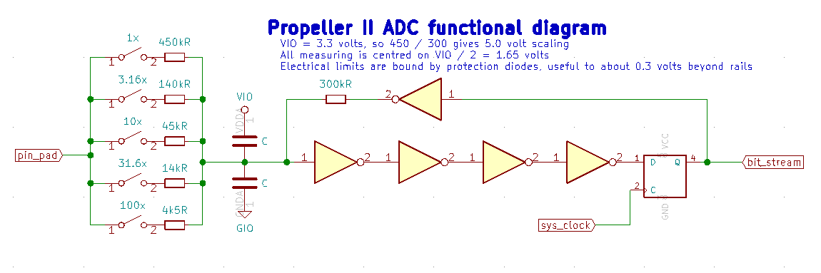
What is the size of these capacitors "C"? As far as I understand, this together with R=450k gives the answer to the question, how long you have to wait after switching the input?
Christof