

Improved ADC Pin Techniques
 cgracey
Posts: 14,323
cgracey
Posts: 14,323
I have been on a detour from USB stuff to work out some software techniques for improving instrumentation ADC performance on single I/O pins.
It turns out that SINC2 manual mode in the smart pin can be exploited for making accumulated measurements which integrate many short, interleaved GND, VIO, and pin measurements. This takes very little software and we can get to 16 bits, at least, with long sample times.
Tomorrow, I will post some example code here. This has been very exciting to work on. Every day, I have been able to find ways to realize big improvements, after I thought I had hit hard limits the day before.
Here are some pictures of captured waveforms that are only 1 mV peak-to-peak, across the entire -200mV to +3.5V range, and are 1 Hz, to allow for long sampling times. Samples are reported in microvolts!
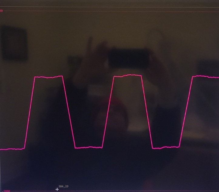
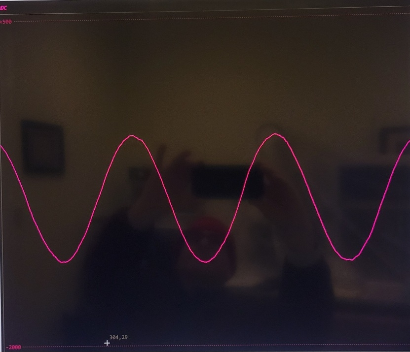
You could use this directly for EKG, for example. No special low-voltage analog circuitry needed.
These techniques can also yield 10-bit instrumentation samples at 250 KHz. By instrumentation, I mean absolute voltage registration, not AC measurements.
Comments
Its great that you're looking at this again, Chip. Richard has also done some more work in this area.
Have you had a look at feeding the same signal into multiple adjacent pins, such as the 4 in a VIO block? I'm curious whether those small ripples in the waveform would be common, or not
This is the idea I also thought of, that can help to limit the ADC input noise... so instead of trying it myself in a more or less distant future now I am waiting for the result
may help or may not help. If the noise source is external (eg. power supply for the pin bank) it will not help at all. If the noise is independent for every ADC (eg. its input amplifier) you will get 3 dB of SNR for every doubling of ADCs used.
I don't know exactly what technique Chip designed. What I thought of was to set short sample period (eg. 512 samples) and then measure VIO,GND,signal... so the accoustic band and lower frequencies noise is measured on the fly and can be substracted from the signal.
So, is there a multi-meter addon board that we can use or some simple circuit that can be put together to play with this. I'm a little hesitant to apply voltage to a pin only to see smoke.
Mike
How about feeding an input signal to a resistor followed up with a 3.6V Zener diode to ground and taking the signal to the P2 from in between the two ? For slow changing signals that should do the trick at almost no cost.
This would be great for these low cost air quality sensors ... Gives analog signal output...
@Maciek,
I was thinking more of a programmable unit where it could read voltages from 0 - 1, 0 - 10, 0 - 20, 0 - 30 volts and maybe had a shunt resister to measure current. There is a programmable resister that could be used as a voltage divider and maybe provide this type of function.
AD5220.
Mike
@iseries,
I get the idea now. My simple solution would only aply to the lowest part of your proposed range so clearly not what you're after.
I thought you just needed to utilize the available ADC range without blowing up the pin.
I don't think I can squeeze any more performance out now, except by lengthening the sample period.
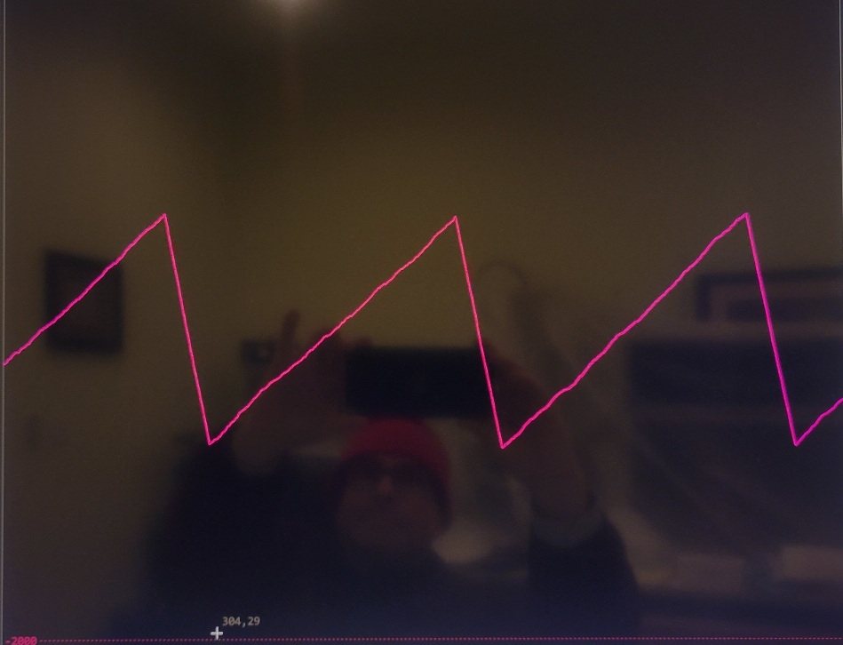
Check this out. This is a 1 mv 20-second sawtooth digitized using three P2 pins. These are the raw sample points:
Hi,
Dump question. Where can this be checked out?
Thanks, Christof
I will post the code today with some explanation. I meant to do it yesterday, but didn't get it done.
I am trying to figure out why I'm getting differing DC levels at different sample resolutions. It's very precise, but has an accuracy issue.
Turns out you need to ignore the first three samples after switching ADC input sources among GIO, VIO, and the external pin, before the SINC2 filter is completely rid of the prior input voltage's effect. So, the fourth sample is the first one you can use that has a pure reading.
There are three things that need to be measured:
1) GIO (internal)
2) VIO (internal)
3) the pin (external)
Once you have those three measurements, you can compute the actual voltage:
uV = (3_300_000 / (VIO - GIO)) * (pin - GIO)
There are some implementation details to optimize the math, like normalizing the (3_300_000 / (VIO - GIO)) term to 32 bits so that the QMUL can be maximum precision, with the product just needing to be shifted by some amount to get the final result.
Anyway, because there are three measurements to be taken, it's nice to use three pins tied together, so that each pin can be measuring either GIO, VIO, or its external pin, which keeps the combined pin impedance constant at about 430k ohms, since one of those three pins will be measuring its external pin at any time. Keeping the impedance constant has the nice effect of not yanking the voltage around that's being measured.
There's no need to determine differences between each pin's GIO, VIO, and external pin reading, because all GIO readings are summed together, all VIO readings are summed together, and all external pin readings are summed together. After some number of measurements are made, you do the math equation on the three accumulators and get your result. The three pins working together yield three times the conversion accuracy of a single pin in the same time span.
I am thinking that audio quality may be improved by making instrumentation readings, since there is some wavy phenomena in raw ADC readings.
I've found that to get good instrumentation readings, you need to spend equal time measuring GIO, VIO, and the external pin. If you try to skimp on the GIO and VIO measurements, thinking that it should be okay, since they don't change that much, the quality of the final result will suffer.
It does take three samples to flush the SINC2 filter in the smart pin from the prior voltage it was connected to. There might even be some residual after three samples, but it seems probably negligible to me, at this point. Anway, by using SINC2 in manual mode, where you compute the differential with two instructions after each sample period, you get many LSBs that contain signal that can be summed. If you tried to sum full-SINC2-conversion-mode samples that didn't have all those LSBs, you would not get much precision gain.
I also experimented with the SINC3 filter mode, but the improvement was very slight, if any, and the bit growth was so rapid that large accumulations for precision measurements were not practical. SINC2 in manual mode is the sweet spot for these kinds of conversions.
Neat idea using the 3 pins to rotate like that, fantastic
One extension of that concept might be to "output low" a ground signal on the 4th pin in that group, and use that as the signal ground (or even as a driven shield).
The trouble with having that one single common ground (albeit solid) is that other cogs and connected I/O share the same current path, outside of the pin pad.
The other thing we noticed back in glob top ADC testing was that the VIO calibration data seemed to have less noise (less variation in readings) than GND. I've always wanted to revisit that, because for some circuits like microphones you could potentially bias from the VIO rail.
I concur. And I'd say you're getting a leg up by keeping the pin impedance steady.
Two full decimations are needed for a step change to flow through the filter. But that's assuming a perfectly synchronised and instant square edge. So an extra decimation is used to allow for the switching of the frontend analogue source to settle out. If settling takes longer than that then it'll still need extra decimations, above three, before beginning of valid samples from the decimator.
That's music to my ears. I never did find out how you computed the ENOB in the Silicon Doc.
That fits the recommendation, that I read about, that states the Sinc filter's order should be chosen as ADC modulator's order + 1.
Nice. I pondering doing exactly that, okay not three pins though, but never stayed focused and never wrote it down so it got lost in attention of other activities.
EDIT: Err, no, having read the code now, the critical part is the 8-sample accumulation between source selects. I hadn't pondered it like that at all. This also explains the importance of the strict 3-source cycle.
I’d personally like to use just one pin even if update rate is reduced 3X
Also I think the word “instrumentation” often implies differential measurements…
You can strip this down to make it one pin. I'll do that tomorrow.
Instrumentation - I need a word that means GND-VIO-registered.
Makes sense about modulator's-order-plus-one.
The place where I saw SINC3 shine was in the Goertzel circuit. It really improves selectivity.
I think that optimistic doubling of ENOB would only be if we had a second-order analog modulator. Need to change the docs.
I think you are right about the pin not changing exactly on the timing boundary, causing messiness in the decimator. Really, it can't change so cleanly, ever, because there is some charge sharing going on whenever it switches sources and, being analog, it must internally settle over a small fraction of a microsecond. That's got to be why we need three whole cycles. The first one is messy and the other two clean up.
On a related ADC matter, I've been thinking about scope data. Oversampling could be done with the down ramp of the previous Hann/Tukey window coinciding exactly with the up ramp of the next one. If overlap is perfect then all ADC bits will have equal weight. For Hann window I think successive samples must be taken every 15 cycles. If four samples were done then the window would look like a 70-tap Tukey. Whether the results would be better than the inbuilt 68-tap Tukey I don't know.
Here is the code for the three-pin ADC with accurate calibration and maximized math.
How would we control the up and down ramp, since the bits flow through the window at the same time? The filter stays still and the data stream goes through it. We would have to stall the data stream, then?
But a particular ADC bit takes a certain time to pass through and the time between oversamples must be less than this propagation time. Either it will work or I'm talking nonsense.
I can't picture how it would work.
Here is a single-pin version of the ADC program.
I guess a usual question with precise adc is how well it reacts to temperature changes…
The 28-tap Hann window is actually 30-tap, with a zero tap at either end. Imagine at time t = 0 a particular ADC bit coincides with the zero at the bottom of the up ramp. At t = 15 cycles this bit will coincide with the max value at the top of the down ramp. The bit that was at the top of the up ramp at t = 0 will coincide will the zero at the bottom of the down ramp at t = 15. All other bits that were on the down ramp at t = 0 will have been shifted out completely at t = 15. The t = 0 and t = 15 values sum to the max value for all bits, resulting in equal weighting.
Huh, Chip, this problem seems to have gone away on me - https://forums.parallax.com/discussion/comment/1552065/#Comment_1552065
Given you're now happily using exactly what I'd complained about I'm now guessing I was triggering a Flexspin compiler bug back then. I'm now using a newer version of Flexspin, and presumably you never struck any such problem using Pnut in the interim?