@chintan_joshi said:
oh Yes , thank you. with this update i am getting 25 c temperature. But after removing Temp_pin also i am getting same temperature so how this is possible?
Not sure exactly what removing means but an unconnected pin ADC will be at VIO/2. 25 C beta reference is also at VIO/2 (where Rt == R0).
That's why I used the 150 kR internal bias resistor in my testing. I didn't have a real thermistor so imagined one with the bias. EDIT: I probably should have called it a simulated thermistor rather than just a bland bias.
@evanh I have tried two different thermistors with P2. One is cartridge internal thermistor and another one is used for room temperature. Both thermistor showing temperature as 25 c. So looks like issue with our Analog read using P2.
Because one thermistor used for room temperature showing proper room temperature with Arduino interfacing.
Are we missing any setup for analogread using P2? Let me create new thread for Analog read using P2. So it will be proper reference for other developers.
Hmm, hang-on, there is something weird going on when I change things. It might be a C optimiser issue ....
EDIT: Okay, no, that was me.
Separately, and more relevant, I've found that the quantity of decimations for settling weren't even close to enough. Dunno how it was working actually.
I've added a settling parameter to pinwait() and made it a single loop. My testing requires 10 or 11 decimations until settled - which is a lot! Must be something to do with the high input impedance. You may find a different value is better with a real thermistor. The test code tries settling values of 3 to 19.
PS: Settling of 11 means a longer 25 microseconds per sample.
@evanh said:
Hmm, hang-on, there is something weird going on when I change things. It might be a C optimiser issue ....
EDIT: Okay, no, that was me.
Separately, and more relevant, I've found that the quantity of decimations for settling weren't even close to enough. Dunno how it was working actually.
I've added a settling parameter to pinwait() and made it a single loop. My testing requires 10 or 11 decimations until settled - which is a lot! Must be something to do with the high input impedance. You may find a different value is better with a real thermistor. The test code tries settling values of 3 to 19.
PS: Settling of 11 means a longer 25 microseconds per sample.
Still its giving same output with thermistor.
( Entering terminal mode.  Press Ctrl-] or Ctrl-Z to exit. )

   clkfreq = 100000000   clkmode = 0x100090b
      pin P14
duration = 1433  gio = 11807  vio = 55176  value = 32625  Temperature = 22.91177
3  Ratio = 1.083245  rln = 0.079961
duration = 1546  gio = 11818  vio = 55200  value = 33543  Temperature = 25.08248
8  Ratio = 0.996870  rln = -0.003135
duration = 1618  gio = 11819  vio = 55212  value = 33553  Temperature = 25.09094
2  Ratio = 0.996549  rln = -0.003457
duration = 1738  gio = 11808  vio = 55192  value = 33552  Temperature = 25.12612
8  Ratio = 0.995217  rln = -0.004794
duration = 1986  gio = 11820  vio = 55205  value = 33547  Temperature = 25.08368
0  Ratio = 0.996824  rln = -0.003181
duration = 1994  gio = 11818  vio = 55213  value = 33550  Temperature = 25.08368
0  Ratio = 0.996825  rln = -0.003180
duration = 2122  gio = 11813  vio = 55197  value = 33553  Temperature = 25.11645
6  Ratio = 0.995584  rln = -0.004426
duration = 2258  gio = 11814  vio = 55219  value = 33570  Temperature = 25.12973
1  Ratio = 0.995082  rln = -0.004930
duration = 2386  gio = 11812  vio = 55210  value = 33564  Temperature = 25.12854
1  Ratio = 0.995127  rln = -0.004885
duration = 2514  gio = 11805  vio = 55196  value = 33550  Temperature = 25.12005
6  Ratio = 0.995447  rln = -0.004563
@evanh said:
Ha, need to invert to match your voltages ... bias now at 0.352 V with inverted calculation:
      pin P8
duration = 1425  gio = 12838  vio = 55880  value = 14306  Temperature = 149.719940  Ratio = 0.035311  rln = -3.343575
duration = 1602  gio = 12809  vio = 55879  value = 15536  Temperature = 117.946900  Ratio = 0.067595  rln = -2.694216
duration = 1642  gio = 12804  vio = 55870  value = 16255  Temperature = 106.794640  Ratio = 0.087114  rln = -2.440543
duration = 1770  gio = 12796  vio = 55870  value = 16674  Temperature = 101.434930  Ratio = 0.098939  rln = -2.313255
duration = 1906  gio = 12818  vio = 55876  value = 16939  Temperature = 98.657500  Ratio = 0.105838  rln = -2.245850
duration = 2074  gio = 12834  vio = 55893  value = 17125  Temperature = 96.835200  Ratio = 0.110684  rln = -2.201076
duration = 2194  gio = 12804  vio = 55875  value = 17230  Temperature = 95.457120  Ratio = 0.114530  rln = -2.166921
duration = 2330  gio = 12818  vio = 55872  value = 17276  Temperature = 95.116880  Ratio = 0.115504  rln = -2.158449
duration = 2450  gio = 12794  vio = 55869  value = 17324  Temperature = 94.422250  Ratio = 0.117525  rln = -2.141104
duration = 2586  gio = 12798  vio = 55889  value = 17380  Temperature = 93.929290  Ratio = 0.118985  rln = -2.128756
duration = 2698  gio = 12794  vio = 55891  value = 17380  Temperature = 93.896610  Ratio = 0.119083  rln = -2.127936
duration = 2842  gio = 12817  vio = 55875  value = 17390  Temperature = 93.982850  Ratio = 0.118826  rln = -2.130099
duration = 2978  gio = 12802  vio = 55880  value = 17389  Temperature = 93.867220  Ratio = 0.119171  rln = -2.127199
duration = 3106  gio = 12816  vio = 55875  value = 17402  Temperature = 93.857300  Ratio = 0.119200  rln = -2.126949
duration = 3226  gio = 12812  vio = 55866  value = 17416  Temperature = 93.677430  Ratio = 0.119740  rln = -2.122433
duration = 3354  gio = 12803  vio = 55882  value = 17413  Temperature = 93.645230  Ratio = 0.119837  rln = -2.121624
duration = 3482  gio = 12814  vio = 55875  value = 17418  Temperature = 93.684690  Ratio = 0.119718  rln = -2.122616
Oh god, issue was the pin i was using. If i changed pin from 14 to 55 then its showing proper temperature of cartridge thermistor as well of room temp thermistor. Thank you very much for your help.
Even if i use below code i am getting proper temperature. Also able to get proper temperature with your code as well.
The pin group P12..P15, and however many pins are on the same VIO regulator, will all be suspect. Presumably they have been over-voltaged at some time. I have two groups of eight failed pins on my older "glob-top" Eval Board.
If you want to write the timer code in C then just poll the smartpin to detect next period. Eric has stated there is no attempt to make the FlexC's compiled code interrupt safe. So no support for hooking an ISR.
The quadrature counter smartpin mode can be configured to generate deltas on a metronomic period. All you do is set X to the period, in sysclock ticks, then IN flags high when the period expires. And reading IN automatically clears the flag each time. So each time you get a high you know the next delta count has been produced by the smartpin.
@evanh said:
If you want to write the timer code in C then just poll the smartpin to detect next period. Eric has stated there is no attempt to make the FlexC's compiled code interrupt safe. So no support for hooking an ISR.
The quadrature counter smartpin mode can be configured to generate deltas on a metronomic period. All you do is set X to the period, in sysclock ticks, then IN flags high when the period expires. And reading IN automatically clears the flag each time. So each time you get a high you know the next delta count has been produced by the smartpin.
Yes Thank you, but is there any reference or document or code available for P2 to do PID control ? final outcome we want is to control the Dc motor in closed loop based on encoder readings.
@chintan_joshi said:
Only difference is we can use encoder readings and adjust PWM duty cycle of Dc motor.
Is the PWM direct to the power transistors? Or is it for effective torque? If the latter then PDM (NCO Duty mode) is more responsive option than PWM.
PS: I'm assuming you have an opto-coupler in between and thereby need it pulsed rather than using a DAC.
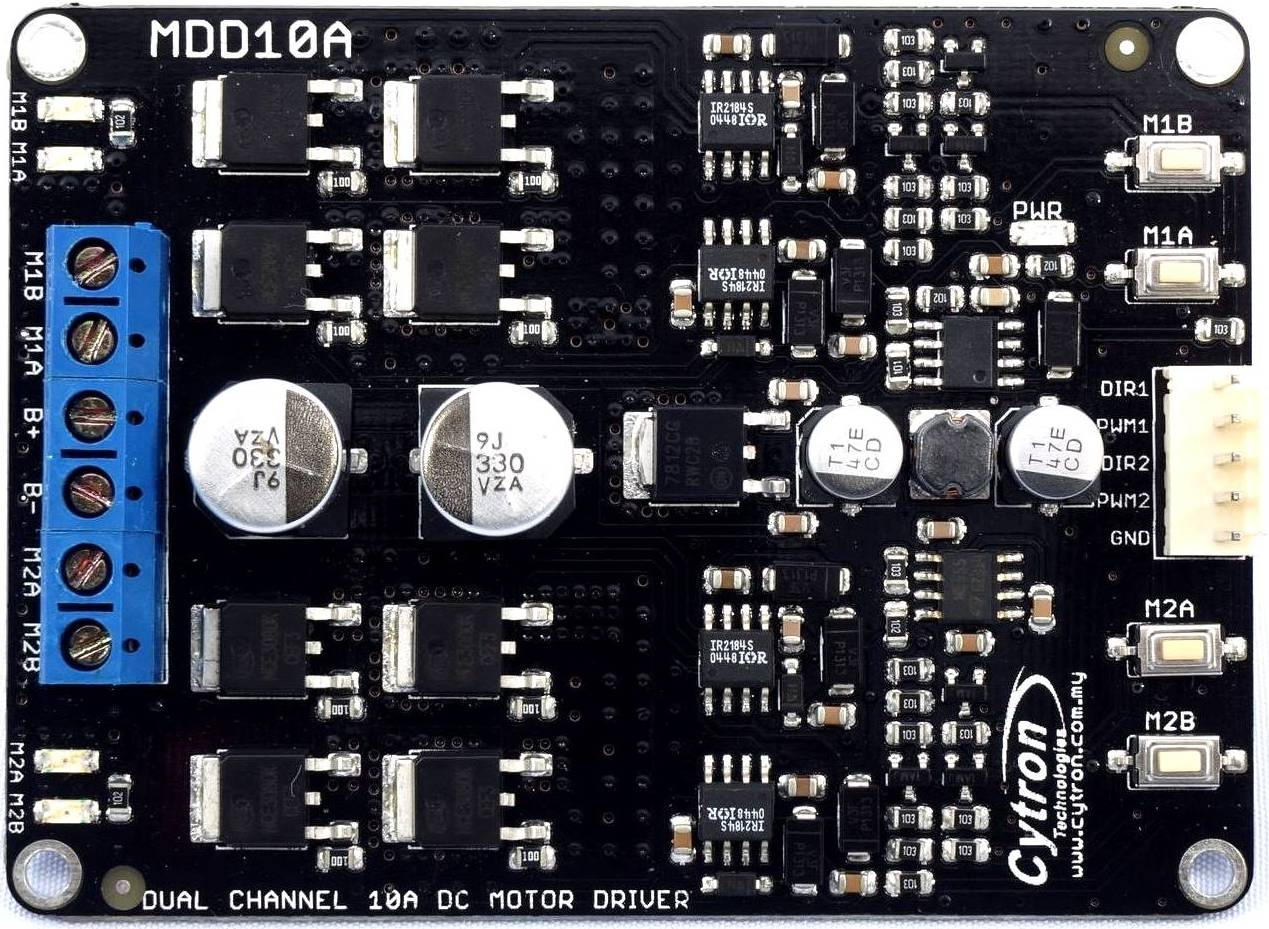
No, i am using cytron Driver(https://robu.in/product/dual-channel-enhanced-13amp-dc-motor-driver-30a-peak/) to drive the DC motor which is attached to the printer cartridge. To drive the DC motor with cytron driver i need two pins 1. Direction and 2. PWM , with PWM pin i can set require speed of the motor. So on normal operation i can drive the Cartridge motor with PWM duty cycle. in this scenario there is no real time checking for cartridge position.
Now i need to update speed(PWM duty ) in closed loop to check in real time for cartridge position using encoder, So need to check cartridge position every 2 ms and update Speed to make it equal distance travel for every 2 ms.
For arduino there is one PID library which can continuously check Encoder position and update PWM duty appropriately, so looking for similar solution for P2.
To use this file i have to call MAIN() of Demo_PILoop.spin2 from c++ code, but before that i have to change pins for 1 motor in spin2 code. and not able to understand What this pin offset and app io pins are declared for?
@whicker , i am trying to update code for single motor and encoder.
i have made below changes , but not able to understand where is motor DIR and PWM pins declared in spin2 code, where can i modify motor DIR and PWM pins to 28 and 29? I have changed Encoder pins in code and changed AXIS_COUNT to 1 and commented out other 3 motors code . can you please help to make this code for single motor and encoder?
''01/17/2022
''rewired to use adafruit DRV8833
''for what it's worth, it's now much less sample time dependent.
''mess with PILOOP_SAMPLES_Hz and speed setpoint
''speed command target_speed_f is now in [motor revolutions per second]
''re-enabled tracking time constant after bug discovered by setting a negative literal value in a pub section.
''as workaround, use the constant "TARGET_SPEED_FLOAT" to change desired motor speed.
''ramp up and down. encoder has more smoothing (at the cost of lag)
''create a PILoop object
''run all 4 motors at the same time
CON { timing }
CLK_FREQ = 200_000_000 ' system freq as a constant
BR_TERM = 230_400 ' terminal baud rate
_clkfreq = CLK_FREQ ' set system clock
CON { fixed io pins }
RX1 = 63 { I } ' programming / debug
TX1 = 62 { O }
SF_CS = 61 { O } ' serial flash
SF_SCK = 60 { O }
SF_SDO = 59 { O }
SF_SDI = 58 { I }
SD_SCK = 61 { O } ' sd card
SD_CS = 60 { O }
SD_SDI = 59 { O }
SD_SDO = 58 { I }
'SDA1 = 57 { IO } ' i2c (optional)
'SCL1 = 56 { IO }
LED_user2 = 57
LED_user1 = 56
CON { pin offsets }
HBRIDGE_NFault = 0 { IO } 'open drain pulls down when fault
HBRIDGE_Enable = 1 { O }
HBRIDGE_AIN_1 = 2 { O }
HBRIDGE_AIN_2 = 3 { O }
HBRIDGE_BIN_2 = 4 { O }
HBRIDGE_BIN_1 = 5 { O }
RIGHT_MOTORS = 0
LEFT_MOTORS = 16
CON { app io pins }
LEFT_MOTORS_FAULT = LEFT_MOTORS + HBRIDGE_NFault
LEFT_MOTORS_ENABLE = LEFT_MOTORS + HBRIDGE_Enable
LEFT_REAR_FWD = LEFT_MOTORS + HBRIDGE_AIN_1
LEFT_REAR_REV = LEFT_MOTORS + HBRIDGE_AIN_2
LEFT_REAR_ENCA = 42
LEFT_REAR_ENCB = 43
''LEFT_FRONT_FWD = LEFT_MOTORS + HBRIDGE_BIN_1
''LEFT_FRONT_REV = LEFT_MOTORS + HBRIDGE_BIN_2
''LEFT_FRONT_ENCA = 10
''LEFT_FRONT_ENCB = 11
''RIGHT_MOTORS_FAULT = RIGHT_MOTORS + HBRIDGE_NFault
''RIGHT_MOTORS_ENABLE = RIGHT_MOTORS + HBRIDGE_Enable
''RIGHT_REAR_FWD = RIGHT_MOTORS + HBRIDGE_AIN_2
''RIGHT_REAR_REV = RIGHT_MOTORS + HBRIDGE_AIN_1
''RIGHT_REAR_ENCB = 12
''RIGHT_REAR_ENCA = 13
''RIGHT_FRONT_FWD = RIGHT_MOTORS + HBRIDGE_BIN_2
''RIGHT_FRONT_REV = RIGHT_MOTORS + HBRIDGE_BIN_1
''RIGHT_FRONT_ENCB = 14
''RIGHT_FRONT_ENCA = 15
CON { user }
AXIS_COUNT = 1 'number of motors
MOTORS_PWM_Hz = 5000 'the pwm motor frequency
PILOOP_SAMPLES_Hz = 20 'TRY 5, 10, 20, 50. it should be better behaved.
PILOOP_WAIT_COUNT = CLK_FREQ / PILOOP_SAMPLES_Hz
SPEED_AT_FULL_PWM = 160 'motor conversion factor speed command to PWM (Make it a speed reachable at 100% PWM in practice. Reduce from measured freewheel speed somewhat to include some expected load.)
K_Val = 2.5 'Increasing this Proportional value pushes back harder and harder against error. 1.0 is unity, so one unit of error produces one unit of pushback.
P_Weight = 0.55 'Optional Weighting value, leave at 1.0 for normal PID overshoot type behavior. A value like 0.5 significantly reduces initial overshoot, but only after correct tuning of K and I.
I_Val = 2.0 'Increasing this value makes the Integration effect stronger, but more likely to cause oscillation. Too small and you never reach setpoint. This is technically 1/I from textbook definition.
TrackTC = 2.0 'Anti-windup filter "time constant" to saturate Integrator . It is the same time unit as your process value (seconds). Higher values allow more Integrator windup (which is bad).
CON {settings}
TARGET_SPEED_FLOAT = 100.0 'motor [rev/sec] SPEED SETPOINT. Ranges from about -20.0 to -160.0 and 20.0 to 160.0 (static friction break requires some deadzone, it'll be start-stop below 20.0).
OBJ
MOT[AXIS_COUNT] : "Motor_DRV8833.spin2"
ENC[AXIS_COUNT] : "Motor_ABEncoder3.spin2"
PID[AXIS_COUNT] : "Motor_PILoop.spin2"
PUB MAIN() | waitForCnt, add_f, target_speed_f, actual_speed_f[4], command_pwm[4]
pinlow(LED_user1)
''Initialization of the motors and encoders:
pullup(LEFT_MOTORS_FAULT, P_HIGH_15K)
''pullup(RIGHT_MOTORS_FAULT, P_HIGH_15K)
waitms(100)
pinhigh(LED_user1)
MOT[0].start(LEFT_REAR_FWD, LEFT_REAR_REV, MOTORS_PWM_Hz)
''MOT[1].start(LEFT_FRONT_FWD, LEFT_FRONT_REV, MOTORS_PWM_Hz)
''MOT[2].start(RIGHT_REAR_FWD, RIGHT_REAR_REV, MOTORS_PWM_Hz)
''MOT[3].start(RIGHT_FRONT_FWD, RIGHT_FRONT_REV, MOTORS_PWM_Hz)
ENC[0].start(LEFT_REAR_ENCA, LEFT_REAR_ENCB, 4, CLK_FREQ)
''ENC[1].start(LEFT_FRONT_ENCA, LEFT_FRONT_ENCB, 4, CLK_FREQ)
''ENC[2].start(RIGHT_REAR_ENCA, RIGHT_REAR_ENCB, 4, CLK_FREQ)
''ENC[3].start(RIGHT_FRONT_ENCA, RIGHT_FRONT_ENCB, 4, CLK_FREQ)
PID[0].start(PILOOP_SAMPLES_Hz, MOT.PWM_REF_MAX, SPEED_AT_FULL_PWM)
''PID[1].start(PILOOP_SAMPLES_Hz, MOT.PWM_REF_MAX, SPEED_AT_FULL_PWM)
''PID[2].start(PILOOP_SAMPLES_Hz, MOT.PWM_REF_MAX, SPEED_AT_FULL_PWM)
''PID[3].start(PILOOP_SAMPLES_Hz, MOT.PWM_REF_MAX, SPEED_AT_FULL_PWM)
waitms(100)
pinlow(LED_user1)
pinhigh(LEFT_MOTORS_ENABLE)
''pinhigh(RIGHT_MOTORS_ENABLE)
''Some commented out code here for open-loop speed measurement:
'target_pwm := -MOT1.PWM_REF_MAX / 2 '50 percent
'MOT1.setpwm(target_pwm)
'waitms(100)
'openloop()
'debug(`SCOPE MyScope SIZE 800 600 SAMPLES 128)
'debug(`MyScope 'PWM' 0 10000 500 10 %1111)
'debug(`MyScope 'Speed' 0 160 500 20 %1111)
'debug(`MyScope 'Setpoint' 0 160 500 20 %1111)
''PI Controller Loop Initialization:
waitForCnt := getct() + PILOOP_WAIT_COUNT
actual_speed_f[0] := ENC[0].update()
''actual_speed_f[1] := ENC[1].update()
''actual_speed_f[2] := ENC[2].update()
''actual_speed_f[3] := ENC[3].update()
target_speed_f := TARGET_SPEED_FLOAT
add_f := 0.75
repeat
''Ramp speed up and down (just as a test)
target_speed_f := target_speed_f +. add_f
if target_speed_f >. 150.0
add_f := 0.0 -. add_f
elseif target_speed_f <. -.150.0
add_f := 0.0 -. add_f
''wait until next loop update
waitct(waitForCnt += PILOOP_WAIT_COUNT)
actual_speed_f[0] := ENC[0].update()
''actual_speed_f[1] := ENC[1].update()
''actual_speed_f[2] := ENC[2].update()
''actual_speed_f[3] := ENC[3].update()
command_pwm[0] := PID[0].update(target_speed_f, actual_speed_f[0] )
''command_pwm[1] := PID[1].update(target_speed_f, actual_speed_f[1] )
''command_pwm[2] := PID[2].update(target_speed_f, actual_speed_f[2] )
''command_pwm[3] := PID[3].update(target_speed_f, actual_speed_f[3] )
MOT[0].setpwm(command_pwm[0] )
''MOT[1].setpwm(command_pwm[1] )
''MOT[2].setpwm(command_pwm[2] )
''MOT[3].setpwm(command_pwm[3] )
PUB openloop(MY_AXIS) | waitForCnt, actual_speed_f, debug1
''this just reports the current speed in a loop
waitForCnt := getct() + PILOOP_WAIT_COUNT
repeat
actual_speed_f := ENC[MY_AXIS].update()
debug1 := round(actual_speed_f)
debug(sdec(debug1))
waitct(waitForCnt += PILOOP_WAIT_COUNT)
PUB pullup(pinfield, type)
''pinfield = just a single pin number, or the field of pins which is a starting pin and the quantity of pins after it.
''type = [P_HIGH_FAST, P_HIGH_1K5, P_HIGH_15K, P_HIGH_150K, P_HIGH_1MA, P_HIGH_100UA, P_HIGH_10UA, P_HIGH_FLOAT]
wrpin(pinfield, type)
pinhigh(pinfield)
@evanh said:
Is the PWM direct to the power transistors? Or is it for effective torque? If the latter then PDM (NCO Duty mode) is more responsive option than PWM.
@chintan_joshi said:
For arduino there is one PID library which can continuously check Encoder position and update PWM duty appropriately, so looking for similar solution for P2.
@chintan_joshi said:
For arduino there is one PID library which can continuously check Encoder position and update PWM duty appropriately, so looking for similar solution for P2.
We can probably use a lot of it. Is there a link?
This is closed match for PID control what @whicker suggested. But its in spin2. Let me check for Arduino Link.
@evanh said:
I just looked at Whicker's code. It is a velocity control loop rather than positional. I suspect you'll be wanting positional control loop.
Yes but he is controlling velocity based on encoder readings, so i thought its same. Because if we can run motor on constant velocity based on encoder readings, then it will do the job to run the cartridge at constant speed.
@chintan_joshi said:
... then it will do the job to run the cartridge at constant speed.
You'll be wanting to know the location of the printhead too I suspect. The usual way is to have a profile generator ramp up from an exact start position, reaching traverse speed, then do print, possibly also at exact locations, then ramp back down to an exact end position.
So the PID function is just a small part of the servo.
The attached C isn't useable by itself but compiles without error and should work when the rest is done. I've converted all the .h C++ privates into equivalent .c statics and replaced the millisecond function call with same flexC function: _getms().


Comments
Not sure exactly what removing means but an unconnected pin ADC will be at VIO/2. 25 C beta reference is also at VIO/2 (where Rt == R0).
That's why I used the 150 kR internal bias resistor in my testing. I didn't have a real thermistor so imagined one with the bias. EDIT: I probably should have called it a simulated thermistor rather than just a bland bias.
@evanh I have tried two different thermistors with P2. One is cartridge internal thermistor and another one is used for room temperature. Both thermistor showing temperature as 25 c. So looks like issue with our Analog read using P2.
Because one thermistor used for room temperature showing proper room temperature with Arduino interfacing.
Are we missing any setup for analogread using P2? Let me create new thread for Analog read using P2. So it will be proper reference for other developers.
More likely you're using the wrong pin. The fact that applying the bias resistor changes the reading also tells you the ADC is working.
@evanh i am using pin 14 as Temp_pin. Yes but with original Thermistor i am not getting proper values.
Hmm, hang-on, there is something weird going on when I change things. It might be a C optimiser issue ....
EDIT: Okay, no, that was me.
Separately, and more relevant, I've found that the quantity of decimations for settling weren't even close to enough. Dunno how it was working actually.
I've added a settling parameter to
pinwait()and made it a single loop. My testing requires 10 or 11 decimations until settled - which is a lot! Must be something to do with the high input impedance. You may find a different value is better with a real thermistor. The test code tries settling values of 3 to 19.PS: Settling of 11 means a longer 25 microseconds per sample.
Still its giving same output with thermistor.
( Entering terminal mode. Press Ctrl-] or Ctrl-Z to exit. ) clkfreq = 100000000 clkmode = 0x100090b pin P14 duration = 1433 gio = 11807 vio = 55176 value = 32625 Temperature = 22.91177 3 Ratio = 1.083245 rln = 0.079961 duration = 1546 gio = 11818 vio = 55200 value = 33543 Temperature = 25.08248 8 Ratio = 0.996870 rln = -0.003135 duration = 1618 gio = 11819 vio = 55212 value = 33553 Temperature = 25.09094 2 Ratio = 0.996549 rln = -0.003457 duration = 1738 gio = 11808 vio = 55192 value = 33552 Temperature = 25.12612 8 Ratio = 0.995217 rln = -0.004794 duration = 1986 gio = 11820 vio = 55205 value = 33547 Temperature = 25.08368 0 Ratio = 0.996824 rln = -0.003181 duration = 1994 gio = 11818 vio = 55213 value = 33550 Temperature = 25.08368 0 Ratio = 0.996825 rln = -0.003180 duration = 2122 gio = 11813 vio = 55197 value = 33553 Temperature = 25.11645 6 Ratio = 0.995584 rln = -0.004426 duration = 2258 gio = 11814 vio = 55219 value = 33570 Temperature = 25.12973 1 Ratio = 0.995082 rln = -0.004930 duration = 2386 gio = 11812 vio = 55210 value = 33564 Temperature = 25.12854 1 Ratio = 0.995127 rln = -0.004885 duration = 2514 gio = 11805 vio = 55196 value = 33550 Temperature = 25.12005 6 Ratio = 0.995447 rln = -0.004563It's a rather strong argument to use a timer to sample after a millisecond instead of iterating on decimations.
Time to use a multimeter to measure the voltage at the pin.
Yes i can able to see voltage starts from 2.5 v, and when i increase room temperature voltage dropping to 1.9v, but still P2 showing 25c
Oh, maybe because pin P14 is package pin 24?
EDIT: I'm definitely getting voltage swing on the assigned pin and a reading change to match. Eg: with bias at 2.926 V
Ha, need to invert to match your voltages ... bias now at 0.352 V with inverted calculation:
Oh god, issue was the pin i was using. If i changed pin from 14 to 55 then its showing proper temperature of cartridge thermistor as well of room temp thermistor. Thank you very much for your help.
Even if i use below code i am getting proper temperature. Also able to get proper temperature with your code as well.
void tsr_thread() { while(true) { float samples[5]; unsigned int beta = 3380; for (int i=0; i< 5; i++) { samples[i] = (uint32_t)_rdpin(Temp_pin); _waitms(300); } double average = 0; for (int i=0; i< 5; i++) { average += samples[i]; printf("\n%d> %f\n",i,samples[i]); } average /= 5; printf("average = %f\n",average); average = ((16383 / average) - 1); //printf("average = %f\n",average); average = 10000 / average; float steinhart; steinhart = average / 10000; // (R/Ro) steinhart = log(steinhart); // ln(R/Ro) steinhart /= beta; // 1/B * ln(R/Ro) steinhart += 1.0 / (25 + 273.15); // + (1/To) steinhart = 1.0 / steinhart; // Invert steinhart -= 273.15; //if(steinhart<25) //enable_substrate(); printf("Temperature = %f\n",steinhart); } }Cool, mystery solved at least.
The pin group P12..P15, and however many pins are on the same VIO regulator, will all be suspect. Presumably they have been over-voltaged at some time. I have two groups of eight failed pins on my older "glob-top" Eval Board.
Hello @evanh i am trying to get quadrature Encoder readings in every 2 ms, to adjust the DC motor Duty cycle.
I am able to get quadrature encoder readings by this setup
Now is there any timer interrupt/ Method available for P2 using c++ to get encoder readings on every 2 ms?
i am thinking to implement this as below.
void get_position() { int count_pos = 0; while(_pollatn()==0); while(true) { buf_pos[count_pos] = getPulses();// get Quadrature encoder readings count_pos = count_pos + 1; _waitms(2); } }If you want to write the timer code in C then just poll the smartpin to detect next period. Eric has stated there is no attempt to make the FlexC's compiled code interrupt safe. So no support for hooking an ISR.
The quadrature counter smartpin mode can be configured to generate deltas on a metronomic period. All you do is set X to the period, in sysclock ticks, then IN flags high when the period expires. And reading IN automatically clears the flag each time. So each time you get a high you know the next delta count has been produced by the smartpin.
Yes Thank you, but is there any reference or document or code available for P2 to do PID control ? final outcome we want is to control the Dc motor in closed loop based on encoder readings.
it is similar to this link, https://learn.parallax.com/tutorials/language/pbasic/pid-control/proportional-integral-and-derivative
Only difference is we can use encoder readings and adjust PWM duty cycle of Dc motor.
ah, that's kind of a whole program thing.
Here's a quick demo of just using the smartpin to time a polling loop (for delta accumulation to 64-bit, and a second smartpin for absolute count):
PS: And the pins are config'd with pull-ups for use with open-collector NPN wired encoder.
Is the PWM direct to the power transistors? Or is it for effective torque? If the latter then PDM (NCO Duty mode) is more responsive option than PWM.
PS: I'm assuming you have an opto-coupler in between and thereby need it pulsed rather than using a DAC.
Here is a closed-loop DC brushed motor project I made that can be used as a starting point.
https://github.com/Haggarman/Demo_PID_Loop
No, i am using cytron Driver(https://robu.in/product/dual-channel-enhanced-13amp-dc-motor-driver-30a-peak/) to drive the DC motor which is attached to the printer cartridge. To drive the DC motor with cytron driver i need two pins 1. Direction and 2. PWM , with PWM pin i can set require speed of the motor. So on normal operation i can drive the Cartridge motor with PWM duty cycle. in this scenario there is no real time checking for cartridge position.
Now i need to update speed(PWM duty ) in closed loop to check in real time for cartridge position using encoder, So need to check cartridge position every 2 ms and update Speed to make it equal distance travel for every 2 ms.
For arduino there is one PID library which can continuously check Encoder position and update PWM duty appropriately, so looking for similar solution for P2.
Hey @whicker, yes this looks similar solution, but not able to understand code due to spin2 language. is there any c++ alternative for this for P2?
i am using only 1 Dc motor motor and 1 encoder.
And in Demo_PILoop5.spin2 file different pin_offset and app io pins are declared for 4 motors and 4 encoders
CON { pin offsets }
  HBRIDGE_NFault = 0  { IO }                            'open drain pulls down when fault
  HBRIDGE_Enable = 1  { O }
  HBRIDGE_AIN_1 =  2  { O }
  HBRIDGE_AIN_2 =  3  { O }
  HBRIDGE_BIN_2 =  4  { O }
  HBRIDGE_BIN_1 =  5  { O }

  RIGHT_MOTORS =   0
  LEFT_MOTORS =   16

CON { app io pins }
  LEFT_MOTORS_FAULT = LEFT_MOTORS + HBRIDGE_NFault
  LEFT_MOTORS_ENABLE = LEFT_MOTORS + HBRIDGE_Enable

  LEFT_REAR_FWD = LEFT_MOTORS + HBRIDGE_AIN_1
  LEFT_REAR_REV = LEFT_MOTORS + HBRIDGE_AIN_2
  LEFT_REAR_ENCA = 8
  LEFT_REAR_ENCB = 9


  LEFT_FRONT_FWD = LEFT_MOTORS + HBRIDGE_BIN_1
  LEFT_FRONT_REV = LEFT_MOTORS + HBRIDGE_BIN_2
  LEFT_FRONT_ENCA = 10
  LEFT_FRONT_ENCB = 11


  RIGHT_MOTORS_FAULT = RIGHT_MOTORS + HBRIDGE_NFault
  RIGHT_MOTORS_ENABLE = RIGHT_MOTORS + HBRIDGE_Enable

  RIGHT_REAR_FWD = RIGHT_MOTORS + HBRIDGE_AIN_2
  RIGHT_REAR_REV = RIGHT_MOTORS + HBRIDGE_AIN_1
  RIGHT_REAR_ENCB = 12
  RIGHT_REAR_ENCA = 13

  RIGHT_FRONT_FWD = RIGHT_MOTORS + HBRIDGE_BIN_2
  RIGHT_FRONT_REV = RIGHT_MOTORS + HBRIDGE_BIN_1
  RIGHT_FRONT_ENCB = 14
  RIGHT_FRONT_ENCA = 15
To use this file i have to call MAIN() of Demo_PILoop.spin2 from c++ code, but before that i have to change pins for 1 motor in spin2 code. and not able to understand What this pin offset and app io pins are declared for?
@whicker , i am trying to update code for single motor and encoder.
i have made below changes , but not able to understand where is motor DIR and PWM pins declared in spin2 code, where can i modify motor DIR and PWM pins to 28 and 29? I have changed Encoder pins in code and changed AXIS_COUNT to 1 and commented out other 3 motors code . can you please help to make this code for single motor and encoder?
''01/17/2022 ''rewired to use adafruit DRV8833 ''for what it's worth, it's now much less sample time dependent. ''mess with PILOOP_SAMPLES_Hz and speed setpoint ''speed command target_speed_f is now in [motor revolutions per second] ''re-enabled tracking time constant after bug discovered by setting a negative literal value in a pub section. ''as workaround, use the constant "TARGET_SPEED_FLOAT" to change desired motor speed. ''ramp up and down. encoder has more smoothing (at the cost of lag) ''create a PILoop object ''run all 4 motors at the same time CON { timing } CLK_FREQ = 200_000_000 ' system freq as a constant BR_TERM = 230_400 ' terminal baud rate _clkfreq = CLK_FREQ ' set system clock CON { fixed io pins } RX1 = 63 { I } ' programming / debug TX1 = 62 { O } SF_CS = 61 { O } ' serial flash SF_SCK = 60 { O } SF_SDO = 59 { O } SF_SDI = 58 { I } SD_SCK = 61 { O } ' sd card SD_CS = 60 { O } SD_SDI = 59 { O } SD_SDO = 58 { I } 'SDA1 = 57 { IO } ' i2c (optional) 'SCL1 = 56 { IO } LED_user2 = 57 LED_user1 = 56 CON { pin offsets } HBRIDGE_NFault = 0 { IO } 'open drain pulls down when fault HBRIDGE_Enable = 1 { O } HBRIDGE_AIN_1 = 2 { O } HBRIDGE_AIN_2 = 3 { O } HBRIDGE_BIN_2 = 4 { O } HBRIDGE_BIN_1 = 5 { O } RIGHT_MOTORS = 0 LEFT_MOTORS = 16 CON { app io pins } LEFT_MOTORS_FAULT = LEFT_MOTORS + HBRIDGE_NFault LEFT_MOTORS_ENABLE = LEFT_MOTORS + HBRIDGE_Enable LEFT_REAR_FWD = LEFT_MOTORS + HBRIDGE_AIN_1 LEFT_REAR_REV = LEFT_MOTORS + HBRIDGE_AIN_2 LEFT_REAR_ENCA = 42 LEFT_REAR_ENCB = 43 ''LEFT_FRONT_FWD = LEFT_MOTORS + HBRIDGE_BIN_1 ''LEFT_FRONT_REV = LEFT_MOTORS + HBRIDGE_BIN_2 ''LEFT_FRONT_ENCA = 10 ''LEFT_FRONT_ENCB = 11 ''RIGHT_MOTORS_FAULT = RIGHT_MOTORS + HBRIDGE_NFault ''RIGHT_MOTORS_ENABLE = RIGHT_MOTORS + HBRIDGE_Enable ''RIGHT_REAR_FWD = RIGHT_MOTORS + HBRIDGE_AIN_2 ''RIGHT_REAR_REV = RIGHT_MOTORS + HBRIDGE_AIN_1 ''RIGHT_REAR_ENCB = 12 ''RIGHT_REAR_ENCA = 13 ''RIGHT_FRONT_FWD = RIGHT_MOTORS + HBRIDGE_BIN_2 ''RIGHT_FRONT_REV = RIGHT_MOTORS + HBRIDGE_BIN_1 ''RIGHT_FRONT_ENCB = 14 ''RIGHT_FRONT_ENCA = 15 CON { user } AXIS_COUNT = 1 'number of motors MOTORS_PWM_Hz = 5000 'the pwm motor frequency PILOOP_SAMPLES_Hz = 20 'TRY 5, 10, 20, 50. it should be better behaved. PILOOP_WAIT_COUNT = CLK_FREQ / PILOOP_SAMPLES_Hz SPEED_AT_FULL_PWM = 160 'motor conversion factor speed command to PWM (Make it a speed reachable at 100% PWM in practice. Reduce from measured freewheel speed somewhat to include some expected load.) K_Val = 2.5 'Increasing this Proportional value pushes back harder and harder against error. 1.0 is unity, so one unit of error produces one unit of pushback. P_Weight = 0.55 'Optional Weighting value, leave at 1.0 for normal PID overshoot type behavior. A value like 0.5 significantly reduces initial overshoot, but only after correct tuning of K and I. I_Val = 2.0 'Increasing this value makes the Integration effect stronger, but more likely to cause oscillation. Too small and you never reach setpoint. This is technically 1/I from textbook definition. TrackTC = 2.0 'Anti-windup filter "time constant" to saturate Integrator . It is the same time unit as your process value (seconds). Higher values allow more Integrator windup (which is bad). CON {settings} TARGET_SPEED_FLOAT = 100.0 'motor [rev/sec] SPEED SETPOINT. Ranges from about -20.0 to -160.0 and 20.0 to 160.0 (static friction break requires some deadzone, it'll be start-stop below 20.0). OBJ MOT[AXIS_COUNT] : "Motor_DRV8833.spin2" ENC[AXIS_COUNT] : "Motor_ABEncoder3.spin2" PID[AXIS_COUNT] : "Motor_PILoop.spin2" PUB MAIN() | waitForCnt, add_f, target_speed_f, actual_speed_f[4], command_pwm[4] pinlow(LED_user1) ''Initialization of the motors and encoders: pullup(LEFT_MOTORS_FAULT, P_HIGH_15K) ''pullup(RIGHT_MOTORS_FAULT, P_HIGH_15K) waitms(100) pinhigh(LED_user1) MOT[0].start(LEFT_REAR_FWD, LEFT_REAR_REV, MOTORS_PWM_Hz) ''MOT[1].start(LEFT_FRONT_FWD, LEFT_FRONT_REV, MOTORS_PWM_Hz) ''MOT[2].start(RIGHT_REAR_FWD, RIGHT_REAR_REV, MOTORS_PWM_Hz) ''MOT[3].start(RIGHT_FRONT_FWD, RIGHT_FRONT_REV, MOTORS_PWM_Hz) ENC[0].start(LEFT_REAR_ENCA, LEFT_REAR_ENCB, 4, CLK_FREQ) ''ENC[1].start(LEFT_FRONT_ENCA, LEFT_FRONT_ENCB, 4, CLK_FREQ) ''ENC[2].start(RIGHT_REAR_ENCA, RIGHT_REAR_ENCB, 4, CLK_FREQ) ''ENC[3].start(RIGHT_FRONT_ENCA, RIGHT_FRONT_ENCB, 4, CLK_FREQ) PID[0].start(PILOOP_SAMPLES_Hz, MOT.PWM_REF_MAX, SPEED_AT_FULL_PWM) ''PID[1].start(PILOOP_SAMPLES_Hz, MOT.PWM_REF_MAX, SPEED_AT_FULL_PWM) ''PID[2].start(PILOOP_SAMPLES_Hz, MOT.PWM_REF_MAX, SPEED_AT_FULL_PWM) ''PID[3].start(PILOOP_SAMPLES_Hz, MOT.PWM_REF_MAX, SPEED_AT_FULL_PWM) waitms(100) pinlow(LED_user1) pinhigh(LEFT_MOTORS_ENABLE) ''pinhigh(RIGHT_MOTORS_ENABLE) ''Some commented out code here for open-loop speed measurement: 'target_pwm := -MOT1.PWM_REF_MAX / 2 '50 percent 'MOT1.setpwm(target_pwm) 'waitms(100) 'openloop() 'debug(`SCOPE MyScope SIZE 800 600 SAMPLES 128) 'debug(`MyScope 'PWM' 0 10000 500 10 %1111) 'debug(`MyScope 'Speed' 0 160 500 20 %1111) 'debug(`MyScope 'Setpoint' 0 160 500 20 %1111) ''PI Controller Loop Initialization: waitForCnt := getct() + PILOOP_WAIT_COUNT actual_speed_f[0] := ENC[0].update() ''actual_speed_f[1] := ENC[1].update() ''actual_speed_f[2] := ENC[2].update() ''actual_speed_f[3] := ENC[3].update() target_speed_f := TARGET_SPEED_FLOAT add_f := 0.75 repeat ''Ramp speed up and down (just as a test) target_speed_f := target_speed_f +. add_f if target_speed_f >. 150.0 add_f := 0.0 -. add_f elseif target_speed_f <. -.150.0 add_f := 0.0 -. add_f ''wait until next loop update waitct(waitForCnt += PILOOP_WAIT_COUNT) actual_speed_f[0] := ENC[0].update() ''actual_speed_f[1] := ENC[1].update() ''actual_speed_f[2] := ENC[2].update() ''actual_speed_f[3] := ENC[3].update() command_pwm[0] := PID[0].update(target_speed_f, actual_speed_f[0] ) ''command_pwm[1] := PID[1].update(target_speed_f, actual_speed_f[1] ) ''command_pwm[2] := PID[2].update(target_speed_f, actual_speed_f[2] ) ''command_pwm[3] := PID[3].update(target_speed_f, actual_speed_f[3] ) MOT[0].setpwm(command_pwm[0] ) ''MOT[1].setpwm(command_pwm[1] ) ''MOT[2].setpwm(command_pwm[2] ) ''MOT[3].setpwm(command_pwm[3] ) PUB openloop(MY_AXIS) | waitForCnt, actual_speed_f, debug1 ''this just reports the current speed in a loop waitForCnt := getct() + PILOOP_WAIT_COUNT repeat actual_speed_f := ENC[MY_AXIS].update() debug1 := round(actual_speed_f) debug(sdec(debug1)) waitct(waitForCnt += PILOOP_WAIT_COUNT) PUB pullup(pinfield, type) ''pinfield = just a single pin number, or the field of pins which is a starting pin and the quantity of pins after it. ''type = [P_HIGH_FAST, P_HIGH_1K5, P_HIGH_15K, P_HIGH_150K, P_HIGH_1MA, P_HIGH_100UA, P_HIGH_10UA, P_HIGH_FLOAT] wrpin(pinfield, type) pinhigh(pinfield)That's option one, the PWM directly modulates the motor.
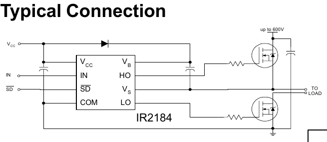
It should have optocouplers but doesn't.
We can probably use a lot of it. Is there a link?
This is closed match for PID control what @whicker suggested. But its in spin2. Let me check for Arduino Link.
Found the Arduino PID library link, https://github.com/br3ttb/Arduino-PID-Library
https://projecthub.arduino.cc/tareqwaleed1996/c9f9b99c-fe07-4250-8799-b81fbf9260da
I just looked at Whicker's code. It is a velocity control loop rather than positional. I suspect you'll be wanting positional control loop.
Yes but he is controlling velocity based on encoder readings, so i thought its same. Because if we can run motor on constant velocity based on encoder readings, then it will do the job to run the cartridge at constant speed.
You'll be wanting to know the location of the printhead too I suspect. The usual way is to have a profile generator ramp up from an exact start position, reaching traverse speed, then do print, possibly also at exact locations, then ramp back down to an exact end position.
So the PID function is just a small part of the servo.
The attached C isn't useable by itself but compiles without error and should work when the rest is done. I've converted all the
.hC++ privates into equivalent.cstatics and replaced the millisecond function call with same flexC function: _getms().