I just looked at the code. Uaagghh! The fonts use a very strange format of reverse packed bits and the code to extract that into pixels looks weired. I think the reason for this was that the original driver by Cluso placed the font data in cog RAM where there was very little space and it wasn't adressable as single bytes but longword-only. I moved the font data to hub RAM which is byte-adressable and there's a lot more space so we can get rid of that ugly format and store the pixels in their natural order.
Speed is also no concern because the scaling doesn't have to be done in real time. I would pre-calculate the font in the desired size and then let the driver just copy it from the memory image. This takes a bit more RAM but it shouldn't be a problem unless you need more than, say, 2 or 3 different font sizes at once.
@msrobots said:
I somehow remember there was a trick to use the P1 font as 2 o 4 bit color, that was the reason for the original font order.
The P1 had the pixels of an even/odd character pair interleaved for that reason. But that has nothing to do with Roger's packed format where the 6x8 font used one and a half longword in cog RAM per character with the byte order swapped.
If anyone want to try, here is the preliminary source code. If it works I'll put it on OBEX/GITHUB.
Depending on the requirements either LCD_FixedFont.spin2 or LCD_VarSizeFont.spin2 can be included, see Demo for an example. You can change the font at any time by calling lcd.SetFont().
Generating the 12x16 font out of the 16x16 image takes ~70ms in Spin. I think that could be sped up by a factor of 10 if optimized in PASM but as it's only required once at startup it doesn't really matter.
@ManAtWork said:
If anyone want to try, here is the preliminary source code. If it works I'll put it on OBEX/GITHUB.
Depending on the requirements either LCD_FixedFont.spin2 or LCD_VarSizeFont.spin2 can be included, see Demo for an example. You can change the font at any time by calling lcd.SetFont().
Generating the 12x16 font out of the 16x16 image takes ~70ms in Spin. I think that could be sped up by a factor of 10 if optimized in PASM but as it's only required once at startup it doesn't really matter.
Fantastic job! Thank you for the update to the driver. Also thank you for providing a way to set the pins through SetLcdPins and SetTouchPins.
Thanks. There may be some cosmetic optimizations to be done. I decided to use a 16x16 image as base for all variable size fonts. The original 16x32 from the P1 ROM would probably be better but would use more memory. Cutting it in half causes aliasing, for example the upper horizontal line of the "E" is thinner than the middle and lower lines. That could be fixed by a more clever anti-aliasing scaling or simply manual pixel painting in the 16x16 source.
In reviewing this thread I remembered I had added a function to my copy of the driver after researching how to fill circles. Maybe there's a better/faster way to do this, but this is what I got. I'll post it here in case someone needs this.
PUB fillCircle(xc, yc, r, rgb)|x,y,xr,yr,d
'Midpoint Circle Algorithm, also known as Bresenham's Circle Algorithm.
  x := 0
  y := r
  d := 1 - r
  repeat while x <= y
    drawLine(xc-x, yc+y, xc+x, yc+y, rgb)
    drawLine(xc-x, yc-y, xc+x, yc-y, rgb)
    drawLine(xc-y, yc+x, xc+y, yc+x, rgb)
    drawLine(xc-y, yc-x, xc+y, yc-x, rgb)

    x++
    if d < 0
      d := d + 2*x + 3
    else
      y--
      d := d + 2*(x - y) + 5
The obvious optimization here is to replace the arbitrary X/Y to X/Y line draw with a specific horizontal/vertical line function. If you're plotting individual pixels when filling a shape, you've already lost. Though looking at the code, it seems there is no such function is implemented, so do that first. IIRC these LCD controllers can do both vertical and horizontal fills quickly.
@Wuerfel_21 said:
The obvious optimization here is to replace the arbitrary X/Y to X/Y line draw with a specific horizontal/vertical line function. If you're plotting individual pixels when filling a shape, you've already lost. Though looking at the code, it seems there is no such function is implemented, so do that first. IIRC these LCD controllers can do both vertical and horizontal fills quickly.
IIRC the Adafruit's library has a fastVLine and a fastHLine that are probably using some feature of the ILI9341. Unfortunately I don't understand most of the terms in the datasheet to be able to figure out what is needed to be done to implement something similar.
PUB fillCircle(xc, yc, r, rgb)|x,y,xr,yr,d
'Midpoint Circle Algorithm, also known as Bresenham's Circle Algorithm.
x := 0
y := r
d := 1 - r
repeat while x <= y
drawFastHLine(xc-x, yc+y, 2*x, rgb)
drawFastHLine(xc-x, yc-y, 2*x, rgb)
drawFastHLine(xc-y, yc+x, 2*y, rgb)
drawFastHLine(xc-y, yc-x, 2*y, rgb)
x++
if d < 0
d := d + 2*x + 3
else
y--
d := d + 2*(x - y) + 5
PUB drawLine(xs, ys, xe, ye, rgb) | i, x, y, dx, dy
' Draw Line - start co-ords, end co-ords, color
dx:= xe - xs
dy:= ye - ys
if dx == 0
drawFastVLine(xs,ys,dy,rgb)
elseif dy == 0
drawFastHLine(xs,ys,dx,rgb)
else
if ABS(dx) > ABS(dy) 'plot incrementing x axis
repeat i from 0 to dx
y := (dy*i + dx/2)/dx
drawPixel(xs+i, ys+y, rgb)
else 'plot incrementing y axis
repeat i from 0 to dy
x := (dx*i + dy/2)/dy
drawPixel(xs+x, ys+i, rgb)
Most of the widgets in my framework use straight lines so this change has a greater impact.
PUB fillCircle(xc, yc, r, rgb)|x,y,xr,yr,d
'Midpoint Circle Algorithm, also known as Bresenham's Circle Algorithm.
x := 0
y := r
d := 1 - r
repeat while x <= y
drawFastHLine(xc-x, yc+y, 2*x, rgb)
drawFastHLine(xc-x, yc-y, 2*x, rgb)
drawFastHLine(xc-y, yc+x, 2*y, rgb)
drawFastHLine(xc-y, yc-x, 2*y, rgb)
x++
if d < 0
d := d + 2*x + 3
else
y--
d := d + 2*(x - y) + 5
It is working much faster than previous approach.
As drawing involves communication with the screen to set the window and fill it, it would be good to do this the minimum number of times (which I think would be 2R times using horizontal lines)
Calculation, on the other hand, should be relatively fast.
At the potential expense of more memory use, I think this might be faster:
PUB fillCircle(xc, yc, r, rgb)|x, y, xs[r], l[r], d
'Midpoint Circle Algorithm, also known as Bresenham's Circle Algorithm.
x := 0
y := r
d := 1 - r
xs[r] := 0
l[r] := 0
repeat while x <= y
xs[y] := xc - x
l[y] := 2*x
xs[x] := xc - y
l[x] := 2*x
x++
if d < 0
d := d + 2*x + 3
else
y--
d := d + 2*(x - y) + 5
repeat x from 0 to r
drawFastHLine(xs[x], yc+x, l[x], rgb)
drawFastHLine(xs[x], yc-x, l[x], rgb)
Interesting... Thanks for the suggestion! Have you perform any testing? If not I could do some testing and post results.
@AJL , I tried to run that code in Propeller Tool, FlexProp and Spin Tools IDE but none of them recognize the syntax for the declaration of xs[r] and l[r]
PUB fillCircle(xc, yc, r, rgb)|x, y, xs[r], l[r], d
It's because of the variable 'r' used in the definition of xs and l - these can't be known at build time. I haven't looked at the code in depth, but I'd assume by the name that the number of elements in the two arrays is meant to be the same as the radius (so maybe define with worst-case?)
@avsa242 said:
It's because of the variable 'r' used in the definition of xs and l - these can't be known at build time. I haven't looked at the code in depth, but I'd assume by the name that the number of elements in the two arrays is meant to be the same as the radius (so maybe define with worst-case?)
I'm not sure I understand. I don't see how that can be done, you cannot know the radius in advance, and I'm not sure it is worth the extra memory considering its current performance is acceptable. If someone manages to do some profiling of the algorithms and the results merit then it would be worth it.
@avsa242 understood my intent. What’s the biggest radius circle you expect the driver to support? That would be the size you’d need to allow for.
If you are satisfied with the performance then that’s fine. It was just a suggestion for the circumstance that you were only marginally happy with the performance you had achieved.
Another thought that I had, but haven’t investigated, would be to determine the corners of boxes (instead of the endpoints of lines.) That would allow a smaller number of setwindow / fillwindow sequences, but each sequence might take the display longer to perform. It wouldn’t need much more memory than what you are currently doing either.
@AJL said:
....
@avsa242 understood my intent. What’s the biggest radius circle you expect the driver to support? That would be the size you’d need to allow for.
....
In my case, since I'm building a framework for creating GUIs in general, I wouldn't want to limit the size of the circle to any given maximum radius. Further, I'm not the OG of the driver, nor an official contributor, I just shared my method here in case someone else would like to use it but I'm sure it would be a welcomed contribution if someone else does it. Again, thanks for the suggestion.
@Electrodude said:
You don't need all those arrays. When Y moves to the next row, plot the previous row using the outermost X values encountered for that row.
Just to close the loop for anyone reading along, this is the slightly faster approach that requires no extra memory:
PUB fillCircle(xc, yc, r, rgb)|x, y, d
'Midpoint Circle Algorithm, also known as Bresenham's Circle Algorithm.
x := 0
y := r
d := 1 - r
repeat while x <= y
x++
if d < 0
d := d + 2*x + 3
else
drawFastHLine(xc-x, yc+y, 2*x, rgb)
drawFastHLine(xc-x, yc-y, 2*x, rgb)
drawFastHLine(xc-y, yc+x, 2*y, rgb)
drawFastHLine(xc-y, yc-x, 2*y, rgb)
y--
d := d + 2*(x - y) + 5
In case someone else needs this, I just added a new method for sending an image's pixel data (word) in 5-6-5 RGB format to the ILI9341 display.
Previously I was using a Spin2 method that called drawPixel() on each pixel of the image, but it was significantly slower.
' Spin2 code
''+-----------------------------------------------------+
'' Added by Jose Rullan
'' mailbox (data): $88 -> sendImage command
'' mailbox1 (data1): imagePtr
''+-----------------------------------------------------+
PUB sendImage(imagePtr,x,y,w,h)
setWindow(x, y, x+w-1, y+h-1)
WaitMailbox()
mailbox1 := imagePtr
mailbox := $88_00_0000
' PASM2 code mods
'...
cmp command, #$88 wz '| $88= paintImage
if_e jmp #send_image_data '|
'...
' PASM2 new code
''+-----------------------------------------------------+
'' Added by Jose Rullan
'' sendImage(imagePtr, x, y, w, h)
'' mailbox1 (data1): imagePtr
''+-----------------------------------------------------+
send_image_data
'Setup FIFO read of image data
rdfast #0, data1
'Send command to ILI9341
mov data, #LCD_RAM_WRITE ' Send LCD_RAM_WRITE command to ILI9341
call #writecmd
'Send pixels to ILI9341
.next_pixel rfword data ' Reads a pixel from imagePtr into data
call #write16data ' Send pixel data to ILI9341
djnz pixelno,#.next_pixel ' Decrement pixelno and if not zero loop for next word (pixel data)
jmp #done
I confess this ended up being simpler than I expected but it took me a while to figure out exactly what to do. First trying to understand existing code to notice the pattern of how a command and data was sent to the ILI9341 (not fully understood yet), then understanding the mailbox parameters mechanism and how to use it from Spin2 and finally, figuring out (by looking at the rest of the code) how to create a loop to send the image pixels.
Feedback is always welcome (even if I don't get it the first time).


Comments
>
That's great. I'm looking forward to test it when it is implemented, it would benefit my UI framework with a better looking font.
I just looked at the code. Uaagghh! The fonts use a very strange format of reverse packed bits and the code to extract that into pixels looks weired. I think the reason for this was that the original driver by Cluso placed the font data in cog RAM where there was very little space and it wasn't adressable as single bytes but longword-only. I moved the font data to hub RAM which is byte-adressable and there's a lot more space so we can get rid of that ugly format and store the pixels in their natural order.
Speed is also no concern because the scaling doesn't have to be done in real time. I would pre-calculate the font in the desired size and then let the driver just copy it from the memory image. This takes a bit more RAM but it shouldn't be a problem unless you need more than, say, 2 or 3 different font sizes at once.
Will take some time, though to update the code...
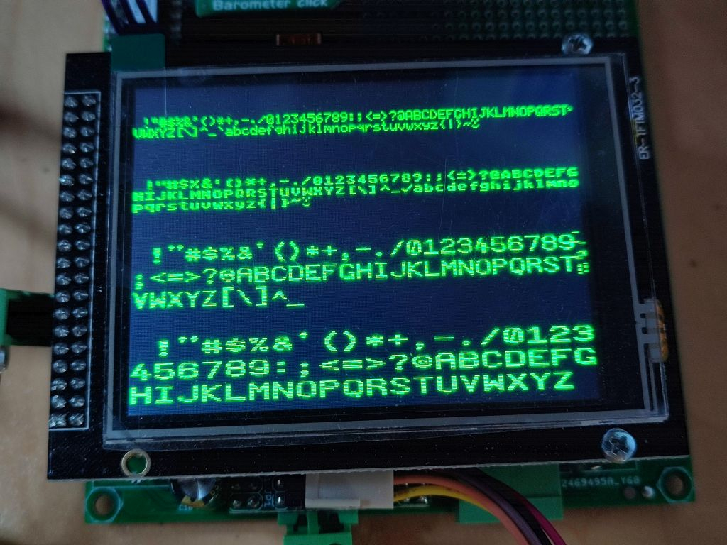
Ok, I figured it out and re-ordered the bytes in the 6x8 and 8x8 fonts. It now looks like this
instead of
The driver should now theoretically work with any font size but I still have to implement the actual scaling.
I somehow remember there was a trick to use the P1 font as 2 o 4 bit color, that was the reason for the original font order.
Mike
Yeah, success!
The P1 had the pixels of an even/odd character pair interleaved for that reason. But that has nothing to do with Roger's packed format where the 6x8 font used one and a half longword in cog RAM per character with the byte order swapped.
looks great
If anyone want to try, here is the preliminary source code. If it works I'll put it on OBEX/GITHUB.
Depending on the requirements either LCD_FixedFont.spin2 or LCD_VarSizeFont.spin2 can be included, see Demo for an example. You can change the font at any time by calling lcd.SetFont().
Generating the 12x16 font out of the 16x16 image takes ~70ms in Spin. I think that could be sped up by a factor of 10 if optimized in PASM but as it's only required once at startup it doesn't really matter.
Excellent! Will try soon enough. Thanks
Fantastic job! Thank you for the update to the driver. Also thank you for providing a way to set the pins through SetLcdPins and SetTouchPins.
Thanks. There may be some cosmetic optimizations to be done. I decided to use a 16x16 image as base for all variable size fonts. The original 16x32 from the P1 ROM would probably be better but would use more memory. Cutting it in half causes aliasing, for example the upper horizontal line of the "E" is thinner than the middle and lower lines. That could be fixed by a more clever anti-aliasing scaling or simply manual pixel painting in the 16x16 source.
@ManAtWork Here is a test video of the driver with my framework:
In reviewing this thread I remembered I had added a function to my copy of the driver after researching how to fill circles. Maybe there's a better/faster way to do this, but this is what I got. I'll post it here in case someone needs this.
PUB fillCircle(xc, yc, r, rgb)|x,y,xr,yr,d 'Midpoint Circle Algorithm, also known as Bresenham's Circle Algorithm. x := 0 y := r d := 1 - r repeat while x <= y drawLine(xc-x, yc+y, xc+x, yc+y, rgb) drawLine(xc-x, yc-y, xc+x, yc-y, rgb) drawLine(xc-y, yc+x, xc+y, yc+x, rgb) drawLine(xc-y, yc-x, xc+y, yc-x, rgb) x++ if d < 0 d := d + 2*x + 3 else y-- d := d + 2*(x - y) + 5I don't know if this is any faster -- it's something I "liberated" from an Arduino graphics library.
pub fill_circle(x, y, radius, color) | x1, y1, err, e2 '' Draw filled circle of radius at x/y x1 := -radius y1 := 0 err := 2-2*radius repeat line(x-x1, y+y1, x-x1, y-y1, color) line(x+x1, y+y1, x+x1, y-y1, color) e2 := err if (e2 <= y1) err += ++y1*2+1 if ((-x1 == y1) && (e2 <= x1)) e2 := 0 if (e2 > x1) err += ++x1*2+1 while (x1 <= 0)The obvious optimization here is to replace the arbitrary X/Y to X/Y line draw with a specific horizontal/vertical line function. If you're plotting individual pixels when filling a shape, you've already lost. Though looking at the code, it seems there is no such function is implemented, so do that first. IIRC these LCD controllers can do both vertical and horizontal fills quickly.
IIRC the Adafruit's library has a fastVLine and a fastHLine that are probably using some feature of the ILI9341. Unfortunately I don't understand most of the terms in the datasheet to be able to figure out what is needed to be done to implement something similar.
Ok, this seems to have improved the fill circle rendering time:
Fiddling with the driver a bit added these two functions:
PUB drawFastHLine(x,y,l,rgb)
    setWindow(x,y,x+l,y)
    fillWindow(rgb)

PUB drawFastVLine(x,y,l,rgb)
    setWindow(x,y,x,y+l)
    fillWindow(rgb)
So the fillCircle function now reads:
PUB fillCircle(xc, yc, r, rgb)|x,y,xr,yr,d
'Midpoint Circle Algorithm, also known as Bresenham's Circle Algorithm.
  x := 0
  y := r
  d := 1 - r
  repeat while x <= y
    drawFastHLine(xc-x, yc+y, 2*x, rgb)
    drawFastHLine(xc-x, yc-y, 2*x, rgb)
    drawFastHLine(xc-y, yc+x, 2*y, rgb)
    drawFastHLine(xc-y, yc-x, 2*y, rgb)

    x++
    if d < 0
      d := d + 2*x + 3
    else
      y--
      d := d + 2*(x - y) + 5
It is working much faster than previous approach.
Did this as well...
PUB drawLine(xs, ys, xe, ye, rgb) | i, x, y, dx, dy
' Draw Line - start co-ords, end co-ords, color
  dx:= xe - xs
  dy:= ye - ys

  if dx == 0
    drawFastVLine(xs,ys,dy,rgb)
  elseif dy == 0
    drawFastHLine(xs,ys,dx,rgb)
  else
    if ABS(dx) > ABS(dy)   'plot incrementing x axis
      repeat i from 0 to dx
        y := (dy*i + dx/2)/dx
        drawPixel(xs+i, ys+y, rgb)
    else 'plot incrementing y axis
      repeat i from 0 to dy
        x := (dx*i + dy/2)/dy
        drawPixel(xs+x, ys+i, rgb)
Most of the widgets in my framework use straight lines so this change has a greater impact.
As drawing involves communication with the screen to set the window and fill it, it would be good to do this the minimum number of times (which I think would be 2R times using horizontal lines)
Calculation, on the other hand, should be relatively fast.
At the potential expense of more memory use, I think this might be faster:
PUB fillCircle(xc, yc, r, rgb)|x, y, xs[r], l[r], d 'Midpoint Circle Algorithm, also known as Bresenham's Circle Algorithm. x := 0 y := r d := 1 - r xs[r] := 0 l[r] := 0 repeat while x <= y xs[y] := xc - x l[y] := 2*x xs[x] := xc - y l[x] := 2*x x++ if d < 0 d := d + 2*x + 3 else y-- d := d + 2*(x - y) + 5 repeat x from 0 to r drawFastHLine(xs[x], yc+x, l[x], rgb) drawFastHLine(xs[x], yc-x, l[x], rgb)Interesting... Thanks for the suggestion! Have you perform any testing? If not I could do some testing and post results.
@AJL , I tried to run that code in Propeller Tool, FlexProp and Spin Tools IDE but none of them recognize the syntax for the declaration of xs[r] and l[r]
It's because of the variable 'r' used in the definition of xs and l - these can't be known at build time. I haven't looked at the code in depth, but I'd assume by the name that the number of elements in the two arrays is meant to be the same as the radius (so maybe define with worst-case?)
I'm not sure I understand. I don't see how that can be done, you cannot know the radius in advance, and I'm not sure it is worth the extra memory considering its current performance is acceptable. If someone manages to do some profiling of the algorithms and the results merit then it would be worth it.
@avsa242 understood my intent. What’s the biggest radius circle you expect the driver to support? That would be the size you’d need to allow for.
If you are satisfied with the performance then that’s fine. It was just a suggestion for the circumstance that you were only marginally happy with the performance you had achieved.
Another thought that I had, but haven’t investigated, would be to determine the corners of boxes (instead of the endpoints of lines.) That would allow a smaller number of setwindow / fillwindow sequences, but each sequence might take the display longer to perform. It wouldn’t need much more memory than what you are currently doing either.
If you aren’t interested I’ll leave it untouched.
That's what I have in my drivers family. Fastline draws a horizontal line from x1 to x2 at y in color c.
'-- A filled circle ----------------------------------------------------- pub fcircle(x0,y0,r,c) | d,x,y,da,db d:=5-4*r x:=0 y:=r da:=(-2*r+5)*4 db:=3*4 repeat while (x<=y) fastline(x0-x,x0+x,y0-y,c) fastline(x0-x,x0+x,y0+y,c) fastline(x0-y,x0+y,y0-x,c) fastline(x0-y,x0+y,y0+x,c) if d>0 d+=da y-=1 x+=1 da+=4*4 db+=2*4 else d+=db x+=1 da+=2*4 db+=2*4In my case, since I'm building a framework for creating GUIs in general, I wouldn't want to limit the size of the circle to any given maximum radius. Further, I'm not the OG of the driver, nor an official contributor, I just shared my method here in case someone else would like to use it but I'm sure it would be a welcomed contribution if someone else does it. Again, thanks for the suggestion.
You don't need all those arrays. When Y moves to the next row, plot the previous row using the outermost X values encountered for that row.
Yes, I see that now.
Just to close the loop for anyone reading along, this is the slightly faster approach that requires no extra memory:
PUB fillCircle(xc, yc, r, rgb)|x, y, d 'Midpoint Circle Algorithm, also known as Bresenham's Circle Algorithm. x := 0 y := r d := 1 - r repeat while x <= y x++ if d < 0 d := d + 2*x + 3 else drawFastHLine(xc-x, yc+y, 2*x, rgb) drawFastHLine(xc-x, yc-y, 2*x, rgb) drawFastHLine(xc-y, yc+x, 2*y, rgb) drawFastHLine(xc-y, yc-x, 2*y, rgb) y-- d := d + 2*(x - y) + 5In case someone else needs this, I just added a new method for sending an image's pixel data (word) in 5-6-5 RGB format to the ILI9341 display.
Previously I was using a Spin2 method that called drawPixel() on each pixel of the image, but it was significantly slower.
' Spin2 code
''+-----------------------------------------------------+
'' Added by Jose Rullan
'' mailbox  (data): $88  -> sendImage command
'' mailbox1 (data1): imagePtr
''+-----------------------------------------------------+
PUB sendImage(imagePtr,x,y,w,h)
  setWindow(x, y, x+w-1, y+h-1)
  WaitMailbox()
  mailbox1 := imagePtr
  mailbox  := $88_00_0000


' PASM2 code mods
'...
                cmp     command, #$88     wz            '| $88= paintImage
        if_e    jmp     #send_image_data                '|
'...


' PASM2 new code
''+-----------------------------------------------------+
'' Added by Jose Rullan
'' sendImage(imagePtr, x, y, w, h)
'' mailbox1 (data1): imagePtr
''+-----------------------------------------------------+
send_image_data
                'Setup FIFO read of image data
                rdfast #0, data1

                'Send command to ILI9341
                mov     data, #LCD_RAM_WRITE            ' Send LCD_RAM_WRITE command to ILI9341
                call    #writecmd

                'Send pixels to ILI9341
.next_pixel     rfword  data                            ' Reads a pixel from imagePtr into data
                call    #write16data                    ' Send pixel data to ILI9341
                djnz    pixelno,#.next_pixel            ' Decrement pixelno and if not zero loop for next word (pixel data)
                jmp     #done
I confess this ended up being simpler than I expected but it took me a while to figure out exactly what to do. First trying to understand existing code to notice the pattern of how a command and data was sent to the ILI9341 (not fully understood yet), then understanding the mailbox parameters mechanism and how to use it from Spin2 and finally, figuring out (by looking at the rest of the code) how to create a loop to send the image pixels.
Feedback is always welcome (even if I don't get it the first time).
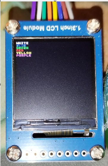
I've tried this with a 1.3 inch LCD, with a ST7789, from WaveShare:
https://www.waveshare.com/1.3inch-lcd-module.htm
LCD_Graphics_Driver_v3.01
Demo:
Driver``, in PRI lcdInit(rotate):
...
```
And it seems to present the colors correct now, black background, and BGR instead of RGB.
It would be good to have a "color list" in the demo, with the colors name/text, in that color.
/M.E.S.H