

HELP WITH PCB FOR CRANES
 MuseumEmployee
Posts: 26
MuseumEmployee
Posts: 26
Hi everyone,
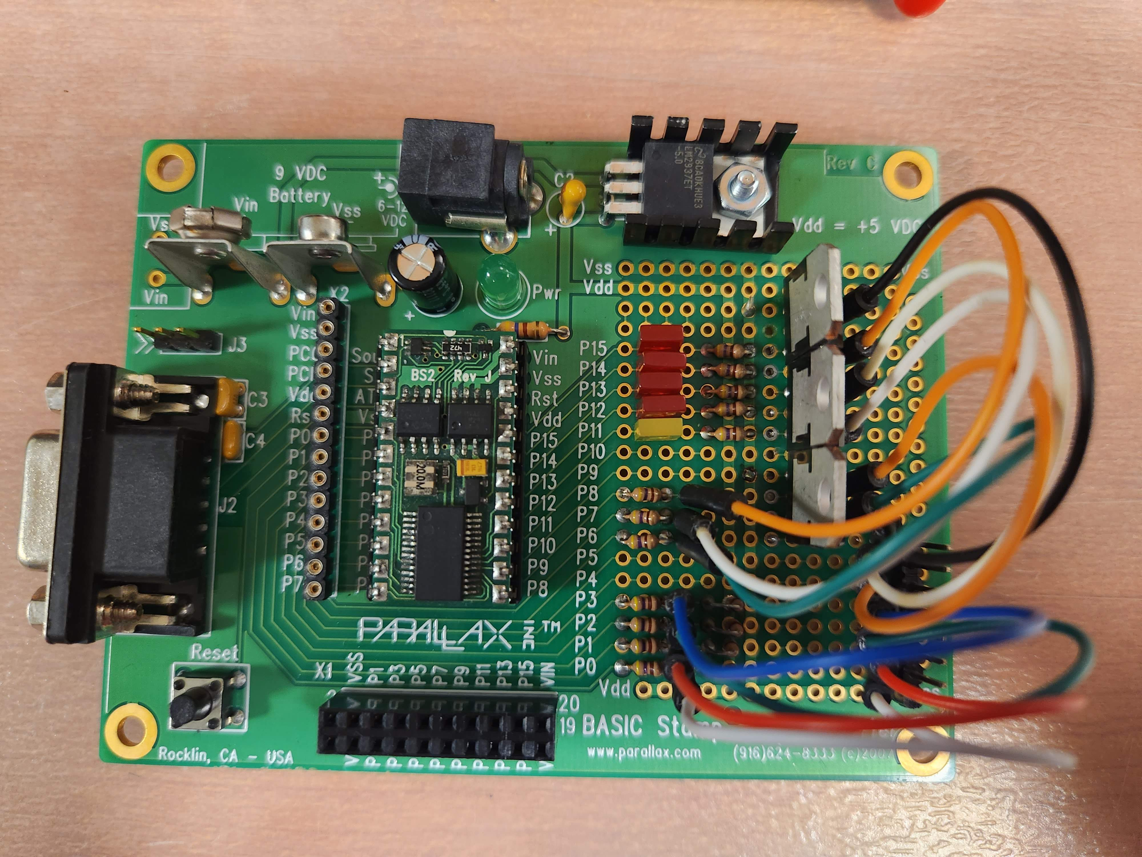
First and foremost, i do not have any experience working on printed circuit boards. I have 2 PCB's that I've recently soldered and mirrored the exact PCB that I pulled out and was working. I went to hook them back up and neither board that I soldered would work. I've tried several different approaches to try and figure out, but I'm still completely stumped. I have checked all the resistors, transistors and relays and all were good. If i do a test on the relay, the motor will kick on and move the cranes like it's supposed to. When i push the button to move the crane forward or backward my motor light will light up and the direction but still no movement from the crane. I have attached some pics of the board i soldered as well as the document that I've been going off of. I'm not sure if my code is wrong since i do not know how to code. Thank you so much in advance for all the help.
A simple relay setup activates the DC motor in 2 directions. Two DPDT relays are used along with
appropriate source transistors. To detect trolley reaching end of rail, two miniature magnetic switches are activated by magnets mounted on the rolling mechanism. A simple 12V light is placed at crank side of each of the trolley rails. When the roller reaches the either end, the light is activated.
The controller circuit listens to the two pushbuttons and activates the two relays accordingly. Since the relays require current at the current output threshold of the BS2, TIP120 transistors are used to beef up current supply.
Comments
Please, when you post photos, reduce them to at most 800 horizontal pixels. That will capture all of the detail you need, and they won't take forever to download, like yours are doing. If the memory footprint of any photo is more than one meg, it's too big. Unfortunately, the forum software has not been rendered smart enough to reduce the resolution of uploaded photos, relying upon the user's browser to do that when they're displayed, hence wasting tons of time and bandwidth.
Thanks,
-Phil
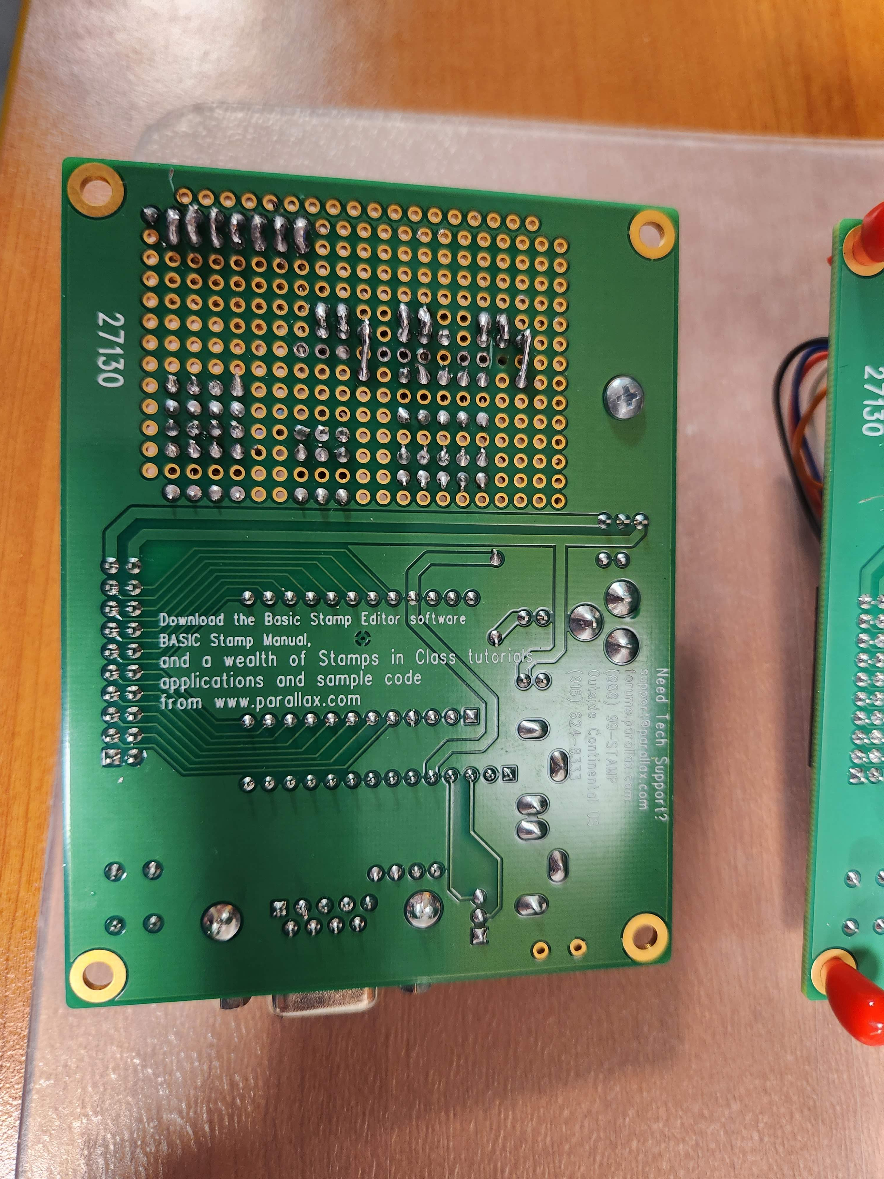
This looks a bit dodgy.
I was just thinking the same;
Additionally to that one, there's a couple more pads that look like they need a bit of extra solder and reflowing again to ensure reliability.
Looks pretty good overall, but probably worth reviewing all the soldering with a magnifier or microscope of some sort.
There isn't anything in that spot, just some left over solder. I had to move the TIP 120's over a row because I messed up one of the plated holes. From my understanding I thought I was ok since I had no copper line running from it to anywhere else. Ill touch up that spot and a few others and see if that helps. Thank you!
Sometimes looking at the top view and bottom view of a PCB can be confusing. I like to stick a wire through the hole next to the terminal I'm tracing as a point of reference. In your documentation I only see half of a schematic. If the board and stamp module are new you'll have to program it. Unless you just swapped it out.
Here is your code
On your center transistor, it looks like your missing the emitter connection.
Lets see a photo of the original board
Do I need to connect my emitter to anything? Again, I was just following the exact board that was pulled out when it was working. I am using a new board but the same BS2 microcontroller. I still ran the basic stamp software and uploaded code from there.
The emitters of the Tip120 are what drive your relay coils. Pin 3 on the transistor's are the emitters, Pin 2 is the collector, and Pin 1 is base. Are the Led's working on your board. Now the BS2 module could have blown out pins, you'll have to test them.
You can run a toggle program and see if your BS2 pin's are going low and high (0 volt and 5 volt)
Yea, all of my Led's are lighting up except for 14 and 15. I can just ground my emitter to VSS right? Where can i run a toggle program. In the basic stamp module?
I read in your first post that you don’t know how to code, but do you have a usb to rs232 adapter and cable. Plus the basic stamp editor on your PC. A toggle program is in the editor. You’ll need a dc volt meter to check pin voltage as the toggle program runs. And emitters should go to Vss.
Yes, I'm using a serial port to rs232 i believe is what it is called and i have the basic stamp editor on this PC as well. I've been able to identify and upload the previous code onto the boards. I did some more research and i may have damaged some parts of the board due to holding the soldering tip on the pads for too long. I'm starting a new board today and I'll make sure to ground my emitters. Thank you so much for the help, I'll let you know how this one goes.
CORRECTION on my part. After reviewing your schematic again the Emitters go to each respective relay coil. So all collectors tie to Vdd (5 Volt +) and then the emttier for one transistor gets connect to the relay coil. It matters which wire on the relay coil you use because of the diode across the coil. Sorry about that.
Here is a clarified schematic
I'm sorry you lost me there.
I don't have any diodes on the board currently. There are 2 diodes either before or after the relays on each side of the crane. None on the board.
The diodes are probably on the relays. But you have to wire the emitter to the correct side of the diode. So emitter to the diode side with black or white line. Depends on the diode some are orange with a black line and some are black with a white line. The line indicates cathode
After zooming in I can the the diodes on the two relays, black with a silver stripe
Yes, correct there are two diodes, but the boards were not wired to the diodes before. I started another board just to be sure it wasn't my soldering and same thing. My motor LED will light up and even my FWD LED and BACK LED when pressing the buttons, but the cranes still do not move themselves.
Here is a link to what the previous boards looked like, as well as the new board I just made.
https://drive.google.com/drive/folders/1k_FsriI_-Hs_d2Q9w1XVungN29OFJDQn?usp=sharing
It would be a good idea to test the relays. Some relays have a mechanical lever you can push. Or with a flat screw driver press the armature, on some you can't. But on yours it might be the blue or red thingy. This way you know the motor works. And check coils by applying 12 VDC to the coils and see if they click on. The Led's working is a good think.
For the relays I was able to pull the blue clip out and like you said, insert a flat screwdriver and the cranes move in the direction they are supposed to. Do I still need to check the coils or does that ensure the relay is working?
Thats good, it looks like you have a 12 vdc power supply for the relays. If can jumper that temporary to each coil, it would tell you that they are working.
Correction 5 VDC for the coils, the motors are 12 VDC
Checkout this schematic
Yea i just pulled all 4 relays out and tested. They were all good to go. I had one that was 24VDC that I pulled out and swapped with another 12V
So, if my Led's are lighting up on my board, then the board should be ok right? And if my relays aren't bad, could it be that I'm not getting enough power to activate my relays? If that is the case, how can I go about checking for that?