        xinit   leadin, #0    // lead-in timing, at sysclock/1
        setq    m_nco2    // streamer transfer rate
        xcont   m_tx, #0    // setup buffered command for tx data
        //dirh  clkpin    // start smartpin internally cycling, at SPI clock rate
        //wypin len, clkpin    // produce clocks, starting on second internal cycle

        drvl    datp    // active data pins for tx data
        dirh    clkpin    // start smartpin internally cycling, at SPI clock rate
        wypin   len, clkpin    // produce clocks, starting on second internal cycle
What does M_LEADIN look like? Does it have a "5" or a "7" length? With that DRVL datp in there it needs to be 7.
EDIT; What I'd do is move the DRVL datp up ahead of the XINIT. Then it won't interfere with the timings and M_LEADIN can stay at 5 ....
M_LEADIN is setup like this, yes its with 5. Let me check with your suggested solution.
@evanh said:
Also, that logic analyser isn't capable of showing correct traces. You are in the dark without trust in the analyser. Get a different one.
Yes, but i can see wrong heaters fired on hardware and this is possible only if we write high on ADATA bit 34 to 31(counting clock from 0). And in the code i have made it off. and in the waveform i can see clock and data mismatch generating ADATA bit 34 to high.
And sadly right now i have only this analyser for High frequency measurements.
Update1: Confirmed that this is code/P2 issue by making ADATA 35th bit 0. Because every time due to data and clock mismtach bit 35 counted as 34th bit and enabled the wrong heater. Making 35th bit Low not enabled the wrong heater. So this is code/ P2 issue.
@evanh said:
Possible data format maybe - Endianess issue. Is there a datasheet for the printhead? And a memory dump of the ADATA content.
Reliable equipment is important. As is, you'd do better to throw that analyser away.
Data is displayed properly on signal lines so not an issue for data format, only issue is starting and stopping point of clock and data bits are not same everytime. its varying everytime. Have you tried write on 4 pins at a time with this DMA code(Hex_t data value is value needs to be write on 4 pins(Pin 16,Pin 17, Pin 18, Pin 19))? may be write to 4 pins at a time creating lagging issue?
The code is well tested. I've used variations of it on multiple 4-bit and 8-bit PSRAM chips with large amounts of verified test data. And no issues showed up on my oscilloscope either. Certainly never had phase jitter, even when parameters were wrong.
Without a reliable logic analyser you are blind to the actual problem. Which leaves you guessing.
@evanh said:
The code is well tested. I've used variations of it on multiple 4-bit and 8-bit PSRAM chips with large amounts of verified test data. And no issues showed up on my oscilloscope either. Certainly never had phase jitter, even when parameters were wrong.
Without a reliable logic analyser you are blind to the actual problem. Which leaves you guessing.
I can understand this may be logic analyser issue, but what i am trying to explain is i am getting wrong addressing , i am sure that addressing code is proper, and that wrong addressing matches to the waveforms i see. And that wrong addressing output matches perfectly to the hardware output. So what i see on analyser same output i am getting on printhead.
@evanh said:
Oh! Make sure Flexspin is up-to-date. There was a nasty bug recent squashed that affected inline Pasm code.
Hey @evanh Thank you for suggesting update.
Updated Flexprop to 5.9.17 and surprisingly majority of lagging disappeared. still its show little lagging between clock and data bits on random places. May be this is due to analyser, because now wrong heaters have not addressed.
PS: That compiler bug was freaky. It depended on certain code size I think. Most of the time it never showed up. But when the conditions were right it wouldn't go away.
i am using Steinhart's Hart equation to read value of thermistor and convert it to temperatue.
this is the code i was using previously for STM32 controller.
void tsr_thread() {
  while (true) {
    unsigned int a, beta = 3380, units, tens;
    float temperature, resistance;
    a = thermistor.read_u16(); /* Read analog value */

    /* Calculate the resistance of the thermistor from analog votage read. */
    resistance = (float)10000.0 * ((65536.0 / a) - 1.0);

    /* Convert the resistance to temperature using Steinhart's Hart equation
     */
    temperature =
        (1 / ((log(resistance / 10000.0) / beta) + (1.0 / 298.15))) - 273.15;
    if (temperature >= 40) {
      printf("Temperature = %d resistance=%d\n", (int)temperature,
             (int)resistance);
    }
    thread_sleep_for(50);
  }
}
And i have created equivalent code for P2 as below
i have initialised pin as
X parameter of 13 is Sinc2 "Sampling" mode with a sample period of 8192 sysclock ticks, which is 14-bit (0 .. 16383) effective. I'm not sure if it's limited to 14 bits though. I think it is.
The "Filtering" modes are not numerically limited to their effective resolution. They can operate to the full 27-bit limit of the Sinc accumulators.
And I'm guessing, to flip the wiring of the thermistor/resistor pair all that has to be changed in software is the value difference: ratio = (float)(vio - gio) / (float)(value - gio) - 1.0;
becomes ratio = (float)(vio - gio) / (float)(vio - value) - 1.0;
@chintan_joshi said:
But can i decrease ADC internal settling/propagation time from 1 ms to 1 us? because for printing algorithm 1 ms is much more time.
Shorter sample period would help a lot, but that degrades the resolution of the samples. Sinc3 can improve the times further but internal ADC noise becomes a problem when trying to do instrumentation like this. You're unlikely to achieve one microsecond and still be toggling the input between GIO, VIO and the pin. Which is quite important for instrumentation measurements since ADC temperature drift is also a concern. The ADCs are far from ideal for instrumentation.
I assume you don't need lots of temperature samples. So, instead of fast sampling, I would recommend using millisecond timers in a polling loop. Or maybe C threads. Dunno if they are supported though.
@evanh said:
PS: I've got Sinc3 down to about 20 us (100 MHz sysclock) for the combined input muxing of one temperature reading.
Hello @EvanVH with this optimised code i am getting this values
( Entering terminal mode. Press Ctrl-] or Ctrl-Z to exit. )
clkfreq = 100000000 clkmode = 0x100090b
pin P0
duration = 1958 gio = 12158 vio = 54886 value = 16723 Temperature = -22.0360
11 Ratio = 8.359912 rln = 2.123448
duration = 1935 gio = 12153 vio = 54866 value = 16690 Temperature = -22.1571
04 Ratio = 8.414371 rln = 2.129941
duration = 1935 gio = 12170 vio = 54877 value = 16709 Temperature = -22.1449
90 Ratio = 8.408900 rln = 2.129291
duration = 1943 gio = 12193 vio = 54885 value = 16716 Temperature = -22.2112
73 Ratio = 8.438868 rln = 2.132848
duration = 1943 gio = 12181 vio = 54868 value = 16721 Temperature = -22.1306
16 Ratio = 8.402423 rln = 2.128520
duration = 1943 gio = 12168 vio = 54859 value = 16725 Temperature = -22.0545
65 Ratio = 8.368225 rln = 2.124442
duration = 1935 gio = 12167 vio = 54897 value = 16731 Temperature = -22.0415
81 Ratio = 8.362401 rln = 2.123746
duration = 1935 gio = 12166 vio = 54864 value = 16700 Temperature = -22.1635
58 Ratio = 8.417292 rln = 2.130288
Temperature displaying in negative numbers. and from previous code also everytime i am getting 23 to 25 c temperature. Evenafter i removed Temp_pin connection from controller. Not sure its issue with Analog reading or TSR.
oh Yes , thank you. with this update i am getting 25 c temperature. But after removing Temp_pin also i am getting same temperature so how this is possible?
Expected temperature should be in between 40 to 65 c. because in cartridge heaters will increase temperature.


Comments
[added to previous post]
M_LEADIN is setup like this, yes its with 5. Let me check with your suggested solution.
@evanh still facing same issue
I have changed M_LEADING to M_LEADIN = X_IMM_32X1_1DAC1 | 7 + CLK_DIV + CLK_REGD - TX_REGD - (1 ^ CPHA) * (CLK_DIV>>1),
and moved the DRVL datp up ahead of the XINIT.
LOL, sorry, have to laugh. Do one or the other, not both. Either move the DRVL or change M_LEADIN to 7.
Also, that logic analyser isn't capable of showing correct traces. You are in the dark without trust in the analyser. Get a different one.
Oh, No issues. I have checked with that also. Moved DRVL only and kept M_LEADING to 5 but still facing same issue.
Yes, but i can see wrong heaters fired on hardware and this is possible only if we write high on ADATA bit 34 to 31(counting clock from 0). And in the code i have made it off. and in the waveform i can see clock and data mismatch generating ADATA bit 34 to high.
And sadly right now i have only this analyser for High frequency measurements.
Update1: Confirmed that this is code/P2 issue by making ADATA 35th bit 0. Because every time due to data and clock mismtach bit 35 counted as 34th bit and enabled the wrong heater. Making 35th bit Low not enabled the wrong heater. So this is code/ P2 issue.
Possible data format maybe - Endianess issue. Is there a datasheet for the printhead? And a memory dump of the ADATA content.
Reliable equipment is important. As is, you'd do better to throw that analyser away.
Oh! Make sure Flexspin is up-to-date. There was a nasty bug recent squashed that affected inline Pasm code.
Data is displayed properly on signal lines so not an issue for data format, only issue is starting and stopping point of clock and data bits are not same everytime. its varying everytime. Have you tried write on 4 pins at a time with this DMA code(Hex_t data value is value needs to be write on 4 pins(Pin 16,Pin 17, Pin 18, Pin 19))? may be write to 4 pins at a time creating lagging issue?
oh! let me check i think i am 1 version behind.
The code is well tested. I've used variations of it on multiple 4-bit and 8-bit PSRAM chips with large amounts of verified test data. And no issues showed up on my oscilloscope either. Certainly never had phase jitter, even when parameters were wrong.
Without a reliable logic analyser you are blind to the actual problem. Which leaves you guessing.
I can understand this may be logic analyser issue, but what i am trying to explain is i am getting wrong addressing , i am sure that addressing code is proper, and that wrong addressing matches to the waveforms i see. And that wrong addressing output matches perfectly to the hardware output. So what i see on analyser same output i am getting on printhead.
Hey @evanh Thank you for suggesting update.
Updated Flexprop to 5.9.17 and surprisingly majority of lagging disappeared. still its show little lagging between clock and data bits on random places. May be this is due to analyser, because now wrong heaters have not addressed.
Good. Sounds like you'll be back on track again.
PS: That compiler bug was freaky. It depended on certain code size I think. Most of the time it never showed up. But when the conditions were right it wouldn't go away.
Hello @evanh
Need little help again.
I am trying to read Cartridge temperature using analogread.
I found this(https://www.parallax.com/simple-analog-input/) post, which is making pin enable to read analog values.
i am using Steinhart's Hart equation to read value of thermistor and convert it to temperatue.
this is the code i was using previously for STM32 controller.
void tsr_thread() { while (true) { unsigned int a, beta = 3380, units, tens; float temperature, resistance; a = thermistor.read_u16(); /* Read analog value */ /* Calculate the resistance of the thermistor from analog votage read. */ resistance = (float)10000.0 * ((65536.0 / a) - 1.0); /* Convert the resistance to temperature using Steinhart's Hart equation */ temperature = (1 / ((log(resistance / 10000.0) / beta) + (1.0 / 298.15))) - 273.15; if (temperature >= 40) { printf("Temperature = %d resistance=%d\n", (int)temperature, (int)resistance); } thread_sleep_for(50); } }And i have created equivalent code for P2 as below
i have initialised pin as
_pinstart(Temp_pin, P_ADC_1X | P_ADC, 13, 0); //init ADC pin
void tsr_thread() {
      unsigned int beta = 3380, units, tens;
    float temperature, resistance;

  while (true) {
    uint32_t a  = _rdpin(Temp_pin);
    //a = thermistor.read_u16(); /* Read analog value */

    /* Calculate the resistance of the thermistor from analog votage read. */
    resistance = (float)10000.0 * ((65536.0 / a) - 1.0);

    /* Convert the resistance to temperature using Steinhart's Hart equation
     */
    temperature =
        (1 / ((log(resistance / 10000.0) / beta) + (1.0 / 298.15))) - 273.15;
    //if (temperature >= 40) {
      printf("Temperature = %d resistance=%d %f\n", (int)temperature,
             (int)resistance,(log(resistance / 10000.0) / beta));
    //}
    _waitms(1000);
  }
}
Below is the output i am getting on print
Is there any alternate method available? because i am getting -18 temperature which is unrealistic.
Oh, I'll need to test all that ...
oh, ok. i have tried to print bunch of samples
        for (int i=0; i< 5; i++)
        {
        samples[i] = (int)_rdpin(Temp_pin);
        _waitms(300);
    }
and i am getting output as
this is analog readings.
X parameter of 13 is Sinc2 "Sampling" mode with a sample period of 8192 sysclock ticks, which is 14-bit (0 .. 16383) effective. I'm not sure if it's limited to 14 bits though. I think it is.
The "Filtering" modes are not numerically limited to their effective resolution. They can operate to the full 27-bit limit of the Sinc accumulators.
ADC isn't entirely passive. It loads its input.
    -0.8553 V = 0
    GIO (0.0 V) =  3190
    float (1.65 V) = 8585 (8192)
    VIO (3.3 V) = 13980
    4.1553 V = 16383
    pull-down at 150 kR = 4350  =>  1160 or 0.35477 V  =>  2.365 uA
    pull-up at 150 kR = 12835  => 9645 or 2.9498 V  =>  2.335 uA
Virtual ground at 1.65 V and calculated input resistance is (1.65 - 0.355) / 2.35e-6 = 550 kR
That's close enough, as per ADC's schematic:
Doing some reading about thermistors tells me your linearising equation is not the Steinhart-Hart equation. What you're using is called the Beta Parameter equation and has a specific range for a given Beta. https://www.jameco.com/Jameco/workshop/TechTip/temperature-measurement-ntc-thermistors.html
Interestingly, R0 and Rt don't have to be individually known. Only need the proportion of full scale voltage.
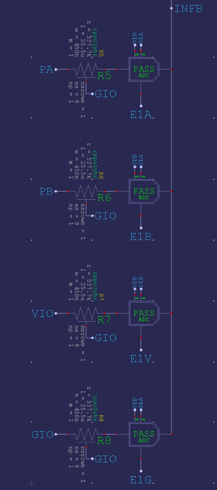
void tsr_loop() { uint32_t value, vio, gio; float temperature, ratio, beta = 3380.0; while (true) { _pinstart(Temp_pin, P_ADC_GIO | P_ADC, 13, 0); _waitms(10); gio = _rdpin(Temp_pin); _pinstart(Temp_pin, P_ADC_VIO | P_ADC, 13, 0); _waitms(10); vio = _rdpin(Temp_pin); _pinstart(Temp_pin, P_ADC_1X | P_ADC, 13, 0); _waitms(10); value = _rdpin(Temp_pin); ratio = (float)(vio - gio) / (float)(value - gio) - 1.0; temperature = 1.0 / (log(ratio) / beta + 1.0 / 298.15) - 273.15; printf( "gio = %d vio = %d value = %d Temperature = %.2f Ratio = %f rln = %f\n", gio, vio, value, temperature, ratio, log(ratio) ); _waitms(900); } }And I'm guessing, to flip the wiring of the thermistor/resistor pair all that has to be changed in software is the value difference:
ratio = (float)(vio - gio) / (float)(value - gio) - 1.0;becomes
ratio = (float)(vio - gio) / (float)(vio - value) - 1.0;PS: I've slightly optimised the sampling code. Reduced the settling times and changed pinstart() to wrpin():
void tsr_loop() { uint32_t value, vio, gio; float temperature, ratio; _pinstart(Temp_pin, P_ADC_1X | P_ADC, 13, 0); //init ADC pin _waitms(10); // warm up the ADC hardware circuits while (true) { _wrpin(Temp_pin, P_ADC_GIO | P_ADC); _waitms(1); // ADC internal settling/propagation time gio = _rdpin(Temp_pin); _wrpin(Temp_pin, P_ADC_VIO | P_ADC); _waitms(1); // ADC internal settling/propagation time vio = _rdpin(Temp_pin); _wrpin(Temp_pin, P_ADC_1X | P_ADC); _waitms(1); // ADC internal settling/propagation time value = _rdpin(Temp_pin); ratio = (float)(vio - gio) / (float)(value - gio) - 1.0; temperature = 1.0 / (log(ratio) / 3380.0 + 1.0 / 298.15) - 273.15; printf( "gio = %d vio = %d value = %d Temperature = %f Ratio = %f rln = %f\n", gio, vio, value, temperature, ratio, log(ratio) ); _waitms(900); } }Ah, that probably relies on R0 == Rt at the relevant beta reference. In this case, 10 kR at 298.15 °K (25.0 °C).
Hello @evanh Thank you for the help. Still i am getting temperature value as 25 , seems like issue in TSR circuit. I will check with my old setup.
But can i decrease ADC internal settling/propagation time from 1 ms to 1 us? because for printing algorithm 1 ms is much more time.
Shorter sample period would help a lot, but that degrades the resolution of the samples. Sinc3 can improve the times further but internal ADC noise becomes a problem when trying to do instrumentation like this. You're unlikely to achieve one microsecond and still be toggling the input between GIO, VIO and the pin. Which is quite important for instrumentation measurements since ADC temperature drift is also a concern. The ADCs are far from ideal for instrumentation.
I assume you don't need lots of temperature samples. So, instead of fast sampling, I would recommend using millisecond timers in a polling loop. Or maybe C threads. Dunno if they are supported though.
PS: I've got Sinc3 down to about 20 us (100 MHz sysclock) for the combined input muxing of one temperature reading.
Hello @EvanVH with this optimised code i am getting this values
( Entering terminal mode.  Press Ctrl-] or Ctrl-Z to exit. )

   clkfreq = 100000000   clkmode = 0x100090b
      pin P0
duration = 1958  gio = 12158  vio = 54886  value = 16723  Temperature = -22.0360
11  Ratio = 8.359912  rln = 2.123448
duration = 1935  gio = 12153  vio = 54866  value = 16690  Temperature = -22.1571
04  Ratio = 8.414371  rln = 2.129941
duration = 1935  gio = 12170  vio = 54877  value = 16709  Temperature = -22.1449
90  Ratio = 8.408900  rln = 2.129291
duration = 1943  gio = 12193  vio = 54885  value = 16716  Temperature = -22.2112
73  Ratio = 8.438868  rln = 2.132848
duration = 1943  gio = 12181  vio = 54868  value = 16721  Temperature = -22.1306
16  Ratio = 8.402423  rln = 2.128520
duration = 1943  gio = 12168  vio = 54859  value = 16725  Temperature = -22.0545
65  Ratio = 8.368225  rln = 2.124442
duration = 1935  gio = 12167  vio = 54897  value = 16731  Temperature = -22.0415
81  Ratio = 8.362401  rln = 2.123746
duration = 1935  gio = 12166  vio = 54864  value = 16700  Temperature = -22.1635
58  Ratio = 8.417292  rln = 2.130288
Temperature displaying in negative numbers. and from previous code also everytime i am getting 23 to 25 c temperature. Evenafter i removed Temp_pin connection from controller. Not sure its issue with Analog reading or TSR.
Oh, you'll want to flip the pin-bias back to none. I left it engaged after my testing of that code.
enum  {PINBIAS = P_ADC_1X | P_ADC};
//enum  {PINBIAS = P_ADC_1X | P_ADC | P_OE | P_LOW_150K};
What temperature was expected, BTW?
oh Yes , thank you. with this update i am getting 25 c temperature. But after removing Temp_pin also i am getting same temperature so how this is possible?
Expected temperature should be in between 40 to 65 c. because in cartridge heaters will increase temperature.