@chintan_joshi said:
Getting surprising result at Clock frequency 8MHZ.
All the noise on AD line goes away. and i can able to see clean data on data lines with clock signal. but 40 clock pulses taking 9 us.
I think that proves the sequence/software is working then. What's now left is electrical connections/layout. I know the Prop2 can electrically drive a high data rate. Even the DACs are plenty fast for video.
BTW: Even that 8 MHz capture still looks rickety. The clock is not evenly spaced at all. Maybe it's just cheap pixel quantised render without antialiasing. It should look far better.
Yes seems working, but timing is issue. On high frequency i am getting noise on signal lines and with 8 MHZ frequency its taking more time which is not useful.
That's always something to be wary of with logic analysers in general. They can't show you the analogue waveform like an oscilloscope can, only the timings.
Ha, funny that the first name I thought of was Agilent. Actually took me a while to realise I was fooled into thinking they were one-and-the-same by the name association. And I'd guess that's intentional.
Again need some help. I want to decrease CLOCK pin frequency. And also that should be sync to all 4 data lines bits as previously. For your reference this is function
I have tried to change M_NCO to 0x4000_0000UL / CLK_DIV + (0x4000_0000UL % CLK_DIV > 0UL ? 1UL : 0UL) but thats not in sync.
Currently pinout8clk_dma() finishing in 340 ns. I want to make it finish in 2.3 us. So which parameters i have to change to Change clock signal(Pin 6) and Data lines (Pins 16,17,18,19) frequency in below dma()?
static uint32_t pinout8clk_dma( unsigned pgroup, unsigned clkpin, int index) { for(int i = 0;i<40;i++) { data_hex[i] = hex_t[index][i]; } unsigned char* haddr = data_hex; int val; int len = 40; uint32_t m_tx = X_RFBYTE_8P_1DAC8 | pgroup<<20 | X_PINS_ON | len; // byte wide transfers from hubRAM, viathe FIFO uint32_t datp = pgroup<<3 | 7<<6; uint32_t ticks = _cnt(); __asm volatile { // no optimising and enforces Fcache use - Needed to free up the FIFO rdfast #0, haddr // setup the FIFO to read from hubRAM, non-blocking setxfrq m_nco1 // set sysclock/1 for lead-in timing xinit leadin, #0 // lead-in timing, at sysclock/1 setq m_nco2 // streamer transfer rate xcont m_tx, #0 // setup buffered command for tx data dirh clkpin // start smartpin internally cycling, at SPI clock rate wypin len, clkpin // produce clocks, starting on second internal cycle drvl datp // active data pins for tx data // dirh clkpin // start smartpin internally cycling, at SPI clock rate // wypin len, clkpin // produce clocks, starting on second internal cycle // twiddle thumbs while DMA happens ... waitxfi // wait for transfer to complete before returning back to hubexec, hubexec uses the FIFO dirl clkpin // reset smartpin _ret_ dirl datp // tristate the data bus upon completion leadin long M_LEADIN m_nco2 long M_NCO m_nco1 long 0x8000_0000 } return _cnt() - ticks; }
Also in Parallel to pinout8clk_dma(), i need to run another function , and both function should start and stop at same time. So i made below code. but still they are not starting and stopping at same time in.
print_cycle() calls pinout8clk_dma()
LoadFire_thread() taking 2.24 us to finish. Thats why i want to finish dma() in 2.3 us. So that both functions can start and stop at same time.
Adjust the CLK_DIV constant. Eight times slower would make it CLK_DIV = 16.
Such a large divider hasn't been tested. With CPHA = 0, you'll probably need to allow more leeway on the data leading the first clock edge. This is done by inserting more delay between the XCONT m_tx and the DIRH clkpin. Also need to put the DRVL datp back where is was as well. It's too late in the sequence where you've put it. eg:
xinit   leadin, #0  // lead-in timing, at sysclock/1
setq    m_nco2      // streamer transfer rate
xcont   m_tx, #0    // setup buffered command for tx data
drvl    datp        // active data pins for tx data
dirh    clkpin       // start smartpin internally cycling, at SPI clock rate
wypin   len, clkpin    // produce clocks, starting on second internal cycle
NOTE: Adding or subtracting instructions requires adjusting M_LEADIN's length parameter. The current length value is 7. If the DRVL is moved elsewhere then subtract 2, making it 5.
Ha, I could automate that CPHA=0 leeway too. It hadn't occurred to me when I was only working with 2..8 divider range ...
Oh, cool, testing reveals it's not needed at all. The initial internal cycling of the clock smartpin extends the start time of the first clock pulse by one whole clock period. This naturally provides the needed leeway. No extra padding to be added.
Nice, now that's sunk in, I can simplify that code section a little. With the imagined timing limitation, from the leading data of CPHA=0, being nulled out by the nature of the PULSE smartpin mode, means I can remove the DRVL instruction. The DRVL becomes an accessory, unrelated to this timing section.
        xinit   leadin, #0    // lead-in timing, at sysclock/1
        setq    m_nco2    // streamer transfer rate
        xcont   m_tx, #0    // setup buffered command for tx data
        dirh    clkpin    // start smartpin internally cycling, at SPI clock rate
        wypin   len, clkpin    // produce clocks, starting on second internal cycle
And the best part is this locks down M_LEADIN's length parameter to the singular value of 5. One less point of confusion.
EDIT: Yeah, and that reaffirms the timing reference point is the DIRH clkpin instruction. The maths pivots on it. There is 5 ticks between start of XINIT command and the DIRH. It's 6 ticks by instruction counting but streamer commands have a one tick lag compared to smartpins.
@evanh said:
Nice, now that's sunk in, I can simplify that code section a little. With the imagined timing limitation, from the leading data of CPHA=0, being nulled out by the nature of the PULSE smartpin mode, means I can remove the DRVL instruction. The DRVL becomes an accessory, unrelated to this timing section.
      xinit   leadin, #0    // lead-in timing, at sysclock/1
      setq    m_nco2    // streamer transfer rate
      xcont   m_tx, #0    // setup buffered command for tx data
      dirh    clkpin    // start smartpin internally cycling, at SPI clock rate
      wypin   len, clkpin    // produce clocks, starting on second internal cycle
And the best part is this locks down M_LEADIN's length parameter to the singular value of 5. One less point of confusion.
EDIT: Yeah, and that reaffirms the timing reference point is the DIRH clkpin instruction. The maths pivots on it. There is 5 ticks between start of XINIT command and the DIRH. It's 6 ticks by instruction counting but streamer commands have a one tick lag compared to smartpins.
Oh Wow, Thank you very much @evanh . i was changing Frequency and forgot about CLK_DIV parameter.
Now clock signals and data signals are in sync with 2.4 us. great.
@chintan_joshi said:
Hello @evanh
Also in Parallel to pinout8clk_dma(), i need to run another function , and both function should start and stop at same time. So i made below code. but still they are not starting and stopping at same time in.
print_cycle() calls pinout8clk_dma()
LoadFire_thread() taking 2.24 us to finish. Thats why i want to finish dma() in 2.3 us. So that both functions can start and stop at same time.
@evanh said:
Nice, now that's sunk in, I can simplify that code section a little. With the imagined timing limitation, from the leading data of CPHA=0, being nulled out by the nature of the PULSE smartpin mode, means I can remove the DRVL instruction. The DRVL becomes an accessory, unrelated to this timing section.
        xinit   leadin, #0    // lead-in timing, at sysclock/1
        setq    m_nco2    // streamer transfer rate
        xcont   m_tx, #0    // setup buffered command for tx data
        dirh    clkpin    // start smartpin internally cycling, at SPI clock rate
        wypin   len, clkpin    // produce clocks, starting on second internal cycle
And the best part is this locks down M_LEADIN's length parameter to the singular value of 5. One less point of confusion.
EDIT: Yeah, and that reaffirms the timing reference point is the DIRH clkpin instruction. The maths pivots on it. There is 5 ticks between start of XINIT command and the DIRH. It's 6 ticks by instruction counting but streamer commands have a one tick lag compared to smartpins.
Oh Wow, Thank you very much @evanh . i was changing Frequency and forgot about CLK_DIV parameter.
Now clock signals and data signals are in sync with 2.4 us. great.
@evanh said:
Nice, now that's sunk in, I can simplify that code section a little. With the imagined timing limitation, from the leading data of CPHA=0, being nulled out by the nature of the PULSE smartpin mode, means I can remove the DRVL instruction. The DRVL becomes an accessory, unrelated to this timing section.
      xinit   leadin, #0    // lead-in timing, at sysclock/1
      setq    m_nco2    // streamer transfer rate
      xcont   m_tx, #0    // setup buffered command for tx data
      dirh    clkpin    // start smartpin internally cycling, at SPI clock rate
      wypin   len, clkpin    // produce clocks, starting on second internal cycle
And the best part is this locks down M_LEADIN's length parameter to the singular value of 5. One less point of confusion.
EDIT: Yeah, and that reaffirms the timing reference point is the DIRH clkpin instruction. The maths pivots on it. There is 5 ticks between start of XINIT command and the DIRH. It's 6 ticks by instruction counting but streamer commands have a one tick lag compared to smartpins.
Oh Wow, Thank you very much @evanh . i was changing Frequency and forgot about CLK_DIV parameter.
Now clock signals and data signals are in sync with 2.4 us. great.
@chintan_joshi said:
Hello @evanh
Also in Parallel to pinout8clk_dma(), i need to run another function , and both function should start and stop at same time. So i made below code. but still they are not starting and stopping at same time in.
print_cycle() calls pinout8clk_dma()
LoadFire_thread() taking 2.24 us to finish. Thats why i want to finish dma() in 2.3 us. So that both functions can start and stop at same time.
Can you please check this as well? When i run Both function in parallel, they are not starting and stopping at same time.
I have used _cogstop(cogid1); and _cogstop(cogid2); after end of both the functions. But seems like its not working.
Best to pre-launch the cogs. Then use synchronising event, eg: COGATN, to align starting of each task's I/O. I don't have any ready examples for this. I did once test it a long time ago, Pasm only, back on the FPGA maybe ...
i am getting 38 clock pulses instead of 40, same for data pins as well.
I have changed len to 41 and now its taking proper 40 clock pulses with proper data pins.
I've just tested your above posted source, ditching the DRVL/DIRL combo and using CLK_DIV = 16 and M_LEADIN = X_IMM_32X1_1DAC1 | 5 + CLK_DIV + CLK_REGD - TX_REGD - (1 ^ CPHA) * (CLK_DIV>>1) with my own data, and all seems fine with len = 40. I can see the data counting up to 40. See attached.
PS: Also ditched the data copy. Just prefilled data_hex[] instead.
EDIT: I just noticed I had a bad comment in my reference source code. The RDFAST is actually the blocking form. So the comment saying it is non-blocking was incorrect. It creeped in from the PSRAM sources - which is the non-blocking form.
Hello @evanh
I have run your sample code(pinwrite-test2.c) as it is. and in that also i am getting 39 falling clock pulses. and also data are moving from 0 to 39. Please check attached image. i have added clock pulse count and data pulse count in image
Well, your snapshot is indicating the data value of 40 on the last clock. And you can even see a tiny spike for the first value of 1 at the start. I can assure you the first clock pulse is present along with the complete first value of 1. My conclusion is your logic analyser still has issues.
@evanh said:
Well, your snapshot is indicating the data value of 40 on the last clock. And you can even see a tiny spike for the first value of 1 at the start. I can assure you the first clock pulse is present along with the complete first value of 1. My conclusion is your logic analyser still has issues.
Yes That tiny spike looks like first pulse, but clock signal starting from second iteration as per snapshot. so clock signal will miss first iteration. Because data will be loaded on every falling edge of the clock. and there are only 39 falling edges observed.
@evanh said:
I've count them on my scope, multiple times. There is 40 clean clock pulses, with a full period of first data value of 1.
I think that logic analyser is still giving you false info.
Then may be its because of High Frequency? I am running with 250 MHZ clock frequency. And if i decreased frequency to 200 MHZ then i am able to see proper 40 clock pulses without any tiny spike. Can you check with 250 MHZ clock frequency? then if you will not get tiny spike then its surely my logic analyser issue.
Hello @evanh i am facing 1 strange issue in Code which run on new cog.
This is my code in which i am starting two different cogs for two parallel processes. and parallely i am running DC motor.
If i start LoadFire_thread() cog as stated below DC motor getting proper signals.
      motor_obj.set_speed(61_0); // 0.23, 65 speed is good
  cogid2 = __builtin_cogstart(LoadFire_thread(),&stack[2]);
  cogid1 = __builtin_cogstart(print_cycle(), &stack[1]);
This is print_cycle() cog code
void print_cycle()
{
for (int index = 0; index < 20; index++)
{
pinout8clk_dma(GROUP, CLK_PIN,index);
}
_cogstop(cogid1);
}
But if i start LoadFire_thread() from different location as given below DC motor not getting any pulses.
static uint32_t pinout8clk_dma( unsigned pgroup, unsigned clkpin, int index)
{
__builtin_cogstart(LoadFire_thread(),&stack[2]);
_waitus(1);//Working
for(int d = 0;d<2;d++); //Additional Delay to start LOAD fire 695ns early before clock cycle
//_waitx(200);//This is not working well
unsigned char* haddr = &hex_t[index][0];
//unsigned char* haddr = data_hex;
int val;
int len = 40;
//_cogatn(cogid2);
uint32_t m_tx = X_RFBYTE_8P_1DAC8 | pgroup<<20 | X_PINS_ON | len; // byte wide transfers from hubRAM, via the FIFO
uint32_t datp = pgroup<<3 | 7<<6;
uint32_t ticks = _cnt();
__asm volatile { // no optimising and enforces Fcache use - Needed to free up the FIFO
rdfast #0, haddr // setup the FIFO to read from hubRAM, non-blocking
setxfrq m_nco1 // set sysclock/1 for lead-in timing
  xinit   leadin, #0    // lead-in timing, at sysclock/1
  setq    m_nco2    // streamer transfer rate
  xcont   m_tx, #0    // setup buffered command for tx data
  dirh    clkpin    // start smartpin internally cycling, at SPI clock rate
  wypin   len, clkpin    // produce clocks, starting on second internal cycle

  drvl    datp    // active data pins for tx data
// dirh clkpin // start smartpin internally cycling, at SPI clock rate
// wypin len, clkpin // produce clocks, starting on second internal cycle
  // twiddle thumbs while DMA happens ...

  waitxfi   // wait for transfer to complete before returning back to hubexec, hubexec uses the FIFO
  dirl    clkpin    // reset smartpin
ret dirl datp // tristate the data bus upon completion
leadin long M_LEADIN
m_nco2 long M_NCO
m_nco1 long 0x8000_0000
}
return _cnt() - ticks;
}
So Not able to understand why DC motor pins got affected with cog code, Motor is not moving when i start (LoadFire_thread())cog from pinout8clk_dma() . Pins i am using for DC motor is 28 and 29. I am using DRV8871 dc motor driver. I have checked signal on logic analyzer and confirms that when i start cog from pinout8clk_dma no signals observed on 28 or 29 motor pins.
Here is the sample code attached to regenerate this issue.
Found the issue, i didn't assigned cogid2 for new cog.> @chintan_joshi said:
Hello @evanh i am facing 1 strange issue in Code which run on new cog.
This is my code in which i am starting two different cogs for two parallel processes. and parallely i am running DC motor.
If i start LoadFire_thread() cog as stated below DC motor getting proper signals.
        motor_obj.set_speed(61_0); // 0.23, 65 speed is good
    cogid2 = __builtin_cogstart(LoadFire_thread(),&stack[2]);
    cogid1 = __builtin_cogstart(print_cycle(), &stack[1]);
This is print_cycle() cog code
void print_cycle()
{
for (int index = 0; index < 20; index++)
{
pinout8clk_dma(GROUP, CLK_PIN,index);
}
_cogstop(cogid1);
}
But if i start LoadFire_thread() from different location as given below DC motor not getting any pulses.
static uint32_t pinout8clk_dma( unsigned pgroup, unsigned clkpin, int index)
{
__builtin_cogstart(LoadFire_thread(),&stack[2]);
_waitus(1);//Working
for(int d = 0;d<2;d++); //Additional Delay to start LOAD fire 695ns early before clock cycle
//_waitx(200);//This is not working well
unsigned char* haddr = &hex_t[index][0];
//unsigned char* haddr = data_hex;
int val;
int len = 40;
//_cogatn(cogid2);
uint32_t  m_tx = X_RFBYTE_8P_1DAC8 | pgroup<<20 | X_PINS_ON | len;  // byte wide transfers from hubRAM, via the FIFO
uint32_t  datp = pgroup<<3 | 7<<6;
uint32_t  ticks = _cnt();

__asm volatile {  // no optimising and enforces Fcache use - Needed to free up the FIFO
    rdfast  #0, haddr    // setup the FIFO to read from hubRAM, non-blocking
    setxfrq m_nco1    // set sysclock/1 for lead-in timing

    xinit   leadin, #0    // lead-in timing, at sysclock/1
    setq    m_nco2    // streamer transfer rate
    xcont   m_tx, #0    // setup buffered command for tx data
    dirh    clkpin    // start smartpin internally cycling, at SPI clock rate
    wypin   len, clkpin    // produce clocks, starting on second internal cycle

    drvl    datp    // active data pins for tx data
// dirh clkpin // start smartpin internally cycling, at SPI clock rate
// wypin len, clkpin // produce clocks, starting on second internal cycle
    // twiddle thumbs while DMA happens ...

    waitxfi   // wait for transfer to complete before returning back to hubexec, hubexec uses the FIFO
    dirl    clkpin    // reset smartpin
_ret_   dirl    datp    // tristate the data bus upon completion
leadin long M_LEADIN
m_nco2 long M_NCO
m_nco1 long 0x8000_0000
}
return _cnt() - ticks;
}
So Not able to understand why DC motor pins got affected with cog code, Motor is not moving when i start (LoadFire_thread())cog from pinout8clk_dma() . Pins i am using for DC motor is 28 and 29. I am using DRV8871 dc motor driver. I have checked signal on logic analyzer and confirms that when i start cog from pinout8clk_dma no signals observed on 28 or 29 motor pins.
Here is the sample code attached to regenerate this issue.
This is the code i am using in pinout8clk_dma function .
40 Clock pulses are properly generated with 2.47us. and all the data loaded on shift register.
But looks like clock signal generation is not same for every instance. Please check attached logic analyser waveforms. Data is loaded on falling edge of the clock.
i have attached 4 instances. and they are one after another.
First instance clock signal starts before data lines.
Second Instance same as first instance.
Third Instance clock signal starts 45ns after data lines and so it stopped after data lines and missed last data bit. this loads wrong data bits.
4th instance clock signal and data signal start and stop at same time and missed last bit.
And i confirmed that this is not logic analyser issue because i have checked output on hardware and due to wrong databits its enabled different heaters of printer. its just about single bit mismatch for ADATA pin. ADATA pin is used for addresing of heaters. So how can we make clock start steady so every time clock signal be in sync with Data bits? Really need your help here. I can provide sample code if this information is not sufficient.
static uint32_t pinout8clk_dma( unsigned pgroup, unsigned clkpin, int index)
{
cogid2 = __builtin_cogstart(LoadFire_thread(),&stack[2]);
_waitus(1);//Working
for(int d = 0;d<2;d++); //Additional Delay to start LOAD fire 695ns early before clock cycle
//_waitx(200);
//unsigned char* haddr = data_hex;
int val;
int len = 40;
//_cogatn(cogid2);
uint32_t m_tx = X_RFBYTE_8P_1DAC8 | pgroup<<20 | X_PINS_ON | len; // byte wide transfers from hubRAM, via the FIFO
uint32_t datp = pgroup<<3 | 7<<6;
uint32_t ticks = _cnt();
__asm volatile { // no optimising and enforces Fcache use - Needed to free up the FIFO
rdfast #0, haddr // setup the FIFO to read from hubRAM, non-blocking
setxfrq m_nco1 // set sysclock/1 for lead-in timing
  xinit   leadin, #0    // lead-in timing, at sysclock/1
  setq    m_nco2    // streamer transfer rate
  xcont   m_tx, #0    // setup buffered command for tx data
  //dirh  clkpin    // start smartpin internally cycling, at SPI clock rate
  //wypin len, clkpin    // produce clocks, starting on second internal cycle

  drvl    datp    // active data pins for tx data
  dirh    clkpin    // start smartpin internally cycling, at SPI clock rate
  wypin   len, clkpin    // produce clocks, starting on second internal cycle

  // twiddle thumbs while DMA happens ...

  waitxfi   // wait for transfer to complete before returning back to hubexec, hubexec uses the FIFO

  dirl    clkpin    // reset smartpin
ret dirl datp // tristate the data bus upon completion
leadin long M_LEADIN
m_nco2 long M_NCO
m_nco1 long 0x8000_0000
}
return _cnt() - ticks;
}
      xinit   leadin, #0    // lead-in timing, at sysclock/1
      setq    m_nco2    // streamer transfer rate
      xcont   m_tx, #0    // setup buffered command for tx data
      //dirh  clkpin    // start smartpin internally cycling, at SPI clock rate
      //wypin len, clkpin    // produce clocks, starting on second internal cycle

      drvl    datp    // active data pins for tx data
      dirh    clkpin    // start smartpin internally cycling, at SPI clock rate
      wypin   len, clkpin    // produce clocks, starting on second internal cycle
What does M_LEADIN look like? Does it have a "5" or a "7" length? With that DRVL datp in there it needs to be 7.
EDIT; What I'd do is move the DRVL datp up ahead of the XINIT. Then it won't interfere with the timings and M_LEADIN can stay at 5 ....


Comments
I think that proves the sequence/software is working then. What's now left is electrical connections/layout. I know the Prop2 can electrically drive a high data rate. Even the DACs are plenty fast for video.
BTW: Even that 8 MHz capture still looks rickety. The clock is not evenly spaced at all. Maybe it's just cheap pixel quantised render without antialiasing. It should look far better.
Is that the analogue bandwidth or the sampling rate?
I am using this analyserhttps://digilent.com/shop/digital-discovery-portable-usb-logic-analyzer-and-digital-pattern-generator/
It showing sampling rate 800MS/s. and i am using 8 channels right now.
8 channels at 800MS/s
Yes seems working, but timing is issue. On high frequency i am getting noise on signal lines and with 8 MHZ frequency its taking more time which is not useful.
@evanh
You were right, Noise was due to logic analyser normal adapter.
I have used High speed adapter to watch the signals. and they are pretty sharp, clean and fast.
Cool. Progress made.")
That's always something to be wary of with logic analysers in general. They can't show you the analogue waveform like an oscilloscope can, only the timings.
Ha, funny that the first name I thought of was Agilent. Actually took me a while to realise I was fooled into thinking they were one-and-the-same by the name association. And I'd guess that's intentional.
Hello @evanh
Again need some help. I want to decrease CLOCK pin frequency. And also that should be sync to all 4 data lines bits as previously. For your reference this is function
I have tried to change M_NCO to 0x4000_0000UL / CLK_DIV + (0x4000_0000UL % CLK_DIV > 0UL ? 1UL : 0UL) but thats not in sync.
Currently pinout8clk_dma() finishing in 340 ns. I want to make it finish in 2.3 us. So which parameters i have to change to Change clock signal(Pin 6) and Data lines (Pins 16,17,18,19) frequency in below dma()?
enum {// _xinfreq = 20_000_000,_xtlfreq = 20_000_000,_clkfreq = 250_000_000,DOWNLOAD_BAUD = 230_400,DEBUG_BAUD = DOWNLOAD_BAUD,PINS = 20|7<<6,GROUP = 2,CLK_PIN = 6,TX_REGD = 1,CLK_REGD = 0,CPOL = 1,CPHA = 0,CLK_DIV = 2,M_NCO = 0x8000_0000UL / CLK_DIV + (0x8000_0000UL % CLK_DIV > 0UL ? 1UL : 0UL), // round upM_LEADIN = X_IMM_32X1_1DAC1 | 7 + CLK_DIV + CLK_REGD - TX_REGD - (1 ^ CPHA) * (CLK_DIV>>1),};static uint32_t pinout8clk_dma( unsigned pgroup, unsigned clkpin, int index){for(int i = 0;i<40;i++){data_hex[i] = hex_t[index][i];}unsigned char* haddr = data_hex;int val;int len = 40;uint32_t m_tx = X_RFBYTE_8P_1DAC8 | pgroup<<20 | X_PINS_ON | len; // byte wide transfers from hubRAM, viathe FIFOuint32_t datp = pgroup<<3 | 7<<6;uint32_t ticks = _cnt();__asm volatile { // no optimising and enforces Fcache use - Needed to free up the FIFOrdfast #0, haddr // setup the FIFO to read from hubRAM, non-blockingsetxfrq m_nco1 // set sysclock/1 for lead-in timingxinit leadin, #0 // lead-in timing, at sysclock/1setq m_nco2 // streamer transfer ratexcont m_tx, #0 // setup buffered command for tx datadirh clkpin // start smartpin internally cycling, at SPI clock ratewypin len, clkpin // produce clocks, starting on second internal cycledrvl datp // active data pins for tx data// dirh clkpin // start smartpin internally cycling, at SPI clock rate// wypin len, clkpin // produce clocks, starting on second internal cycle// twiddle thumbs while DMA happens ...waitxfi // wait for transfer to complete before returning back to hubexec, hubexec uses the FIFOdirl clkpin // reset smartpin_ret_ dirl datp // tristate the data bus upon completionleadin long M_LEADINm_nco2 long M_NCOm_nco1 long 0x8000_0000}return _cnt() - ticks;}Also in Parallel to pinout8clk_dma(), i need to run another function , and both function should start and stop at same time. So i made below code. but still they are not starting and stopping at same time in.
print_cycle() calls pinout8clk_dma()
LoadFire_thread() taking 2.24 us to finish. Thats why i want to finish dma() in 2.3 us. So that both functions can start and stop at same time.
cogid1 = __builtin_cogstart(print_cycle(), &stack[1]);while(_cogchk(cogid2)!=0){;}Adjust the CLK_DIV constant. Eight times slower would make it CLK_DIV = 16.
Such a large divider hasn't been tested. With CPHA = 0, you'll probably need to allow more leeway on the data leading the first clock edge. This is done by inserting more delay between the XCONT m_tx and the DIRH clkpin. Also need to put the DRVL datp back where is was as well. It's too late in the sequence where you've put it. eg:
NOTE: Adding or subtracting instructions requires adjusting M_LEADIN's length parameter. The current length value is 7. If the DRVL is moved elsewhere then subtract 2, making it 5.
Ha, I could automate that CPHA=0 leeway too. It hadn't occurred to me when I was only working with 2..8 divider range ...
Oh, cool, testing reveals it's not needed at all. The initial internal cycling of the clock smartpin extends the start time of the first clock pulse by one whole clock period. This naturally provides the needed leeway. No extra padding to be added.")
Nice, now that's sunk in, I can simplify that code section a little. With the imagined timing limitation, from the leading data of CPHA=0, being nulled out by the nature of the PULSE smartpin mode, means I can remove the DRVL instruction. The DRVL becomes an accessory, unrelated to this timing section.
xinit leadin, #0 // lead-in timing, at sysclock/1 setq m_nco2 // streamer transfer rate xcont m_tx, #0 // setup buffered command for tx data dirh clkpin // start smartpin internally cycling, at SPI clock rate wypin len, clkpin // produce clocks, starting on second internal cycleAnd the best part is this locks down M_LEADIN's length parameter to the singular value of 5. One less point of confusion.")
EDIT: Yeah, and that reaffirms the timing reference point is the
DIRH clkpininstruction. The maths pivots on it. There is 5 ticks between start of XINIT command and the DIRH. It's 6 ticks by instruction counting but streamer commands have a one tick lag compared to smartpins.Oh Wow, Thank you very much @evanh . i was changing Frequency and forgot about CLK_DIV parameter.
Now clock signals and data signals are in sync with 2.4 us. great.
Can you please check this as well? When i run Both function in parallel, they are not starting and stopping at same time.
I have used _cogstop(cogid1); and _cogstop(cogid2); after end of both the functions. But seems like its not working.
Hello @evanh After changing code,
CLK_DIV = 2 to CLK_DIV = 16,
and
M_LEADIN = X_IMM_32X1_1DAC1 | 7 + CLK_DIV + CLK_REGD - TX_REGD - (1 ^ CPHA) * (CLK_DIV>>1) to M_LEADIN = X_IMM_32X1_1DAC1 | 5 + CLK_DIV + CLK_REGD - TX_REGD - (1 ^ CPHA) * (CLK_DIV>>1)
i am getting 38 clock pulses instead of 40, same for data pins as well.
I have changed len to 41 and now its taking proper 40 clock pulses with proper data pins.
Best to pre-launch the cogs. Then use synchronising event, eg: COGATN, to align starting of each task's I/O. I don't have any ready examples for this. I did once test it a long time ago, Pasm only, back on the FPGA maybe ...
I've just tested your above posted source, ditching the DRVL/DIRL combo and using
CLK_DIV = 16andM_LEADIN = X_IMM_32X1_1DAC1 | 5 + CLK_DIV + CLK_REGD - TX_REGD - (1 ^ CPHA) * (CLK_DIV>>1)with my own data, and all seems fine withlen = 40. I can see the data counting up to 40. See attached.PS: Also ditched the data copy. Just prefilled data_hex[] instead.
EDIT: I just noticed I had a bad comment in my reference source code. The RDFAST is actually the blocking form. So the comment saying it is non-blocking was incorrect. It creeped in from the PSRAM sources - which is the non-blocking form.
Hello @evanh
I have run your sample code(pinwrite-test2.c) as it is. and in that also i am getting 39 falling clock pulses. and also data are moving from 0 to 39. Please check attached image. i have added clock pulse count and data pulse count in image
Well, your snapshot is indicating the data value of 40 on the last clock. And you can even see a tiny spike for the first value of 1 at the start. I can assure you the first clock pulse is present along with the complete first value of 1. My conclusion is your logic analyser still has issues.
Yes That tiny spike looks like first pulse, but clock signal starting from second iteration as per snapshot. so clock signal will miss first iteration. Because data will be loaded on every falling edge of the clock. and there are only 39 falling edges observed.
I've count them on my scope, multiple times. There is 40 clean clock pulses, with a full period of first data value of 1.
I think that logic analyser is still giving you false info.
Then may be its because of High Frequency? I am running with 250 MHZ clock frequency. And if i decreased frequency to 200 MHZ then i am able to see proper 40 clock pulses without any tiny spike. Can you check with 250 MHZ clock frequency? then if you will not get tiny spike then its surely my logic analyser issue.
Done. First up is original at 4 MHz sysclock:
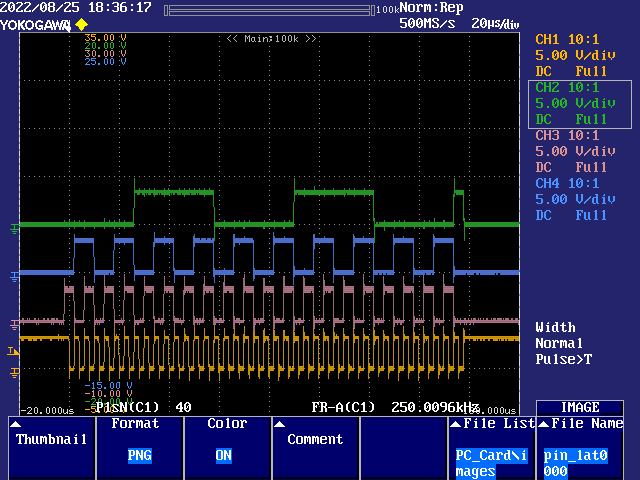
Next up is 160 MHz sysclock:
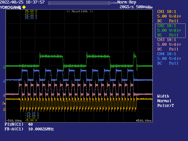
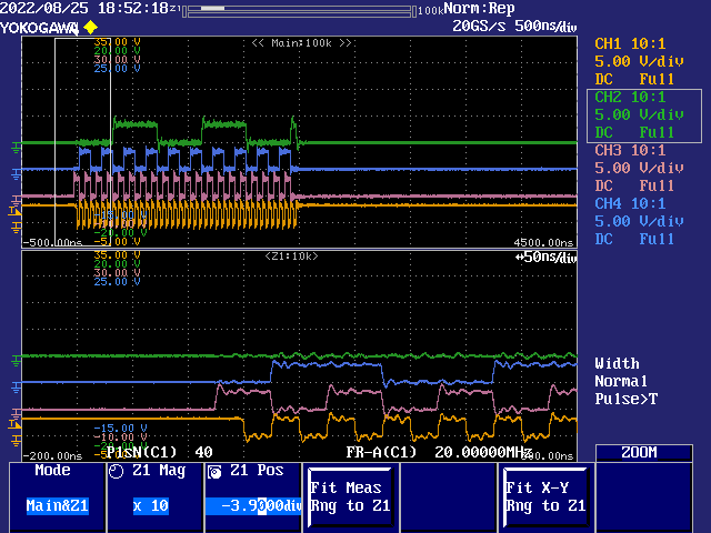
Then 250 MHz sysclock:
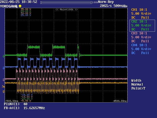
And finally 320 MHz sysclock with a 10x zoom in:
Hello @evanh
Thank you very much for this support and help. Yes it was logic analyser issue.
Glad to help.
Hello @evanh i am facing 1 strange issue in Code which run on new cog.
This is my code in which i am starting two different cogs for two parallel processes. and parallely i am running DC motor.
If i start LoadFire_thread() cog as stated below DC motor getting proper signals.
This is print_cycle() cog code
But if i start LoadFire_thread() from different location as given below DC motor not getting any pulses.
So Not able to understand why DC motor pins got affected with cog code, Motor is not moving when i start (LoadFire_thread())cog from pinout8clk_dma() . Pins i am using for DC motor is 28 and 29. I am using DRV8871 dc motor driver. I have checked signal on logic analyzer and confirms that when i start cog from pinout8clk_dma no signals observed on 28 or 29 motor pins.
Here is the sample code attached to regenerate this issue.
Found the issue, i didn't assigned cogid2 for new cog.> @chintan_joshi said:
Cool. I was a tad tired to look at it at the time.
Hello @evanh
Facing issue in DMA code.
This is the code i am using in pinout8clk_dma function .
40 Clock pulses are properly generated with 2.47us. and all the data loaded on shift register.
But looks like clock signal generation is not same for every instance. Please check attached logic analyser waveforms. Data is loaded on falling edge of the clock.
i have attached 4 instances. and they are one after another.
And i confirmed that this is not logic analyser issue because i have checked output on hardware and due to wrong databits its enabled different heaters of printer. its just about single bit mismatch for ADATA pin. ADATA pin is used for addresing of heaters. So how can we make clock start steady so every time clock signal be in sync with Data bits? Really need your help here. I can provide sample code if this information is not sufficient.
What does M_LEADIN look like? Does it have a "5" or a "7" length? With that
DRVL datpin there it needs to be 7.EDIT; What I'd do is move the
DRVL datpup ahead of the XINIT. Then it won't interfere with the timings and M_LEADIN can stay at 5 ....