One of the nice things about programming a value is you don't have to use different variable names to represent data.
int Rspeed[] = {10, 20, 30, 80};  // <---speed or pulse per seconds.
int Dspeed[] = {8, 20, 30, 80};   // <---speed or pulse per seconds.
This represents the 4 mode speeds that you want to feed to the motors. Mode 0 is 10, 1 is 20, 2 is 30 and 3 is 80.
Now if you find the motors are moving to fast or slow you can change these value to a smaller or larger number instead of changing the code that is working.
I changed them to a smaller value so that you can see the LEDs blink which may not be right for the motors.
At first couldn't get code to upload into sinpleIDE so typed it and found errors, must something wrong with compiler , but I found codes in IDE folder and brought up codes in IDE aplication and uploaded codes into respective devices. happy to say it all works now but i need to change case 'X' to include a pulsed signal when all buttons are at 0 state.
Actually it does make sense since when one is not manually controlling such as slewing or on auto guiding the scope still has to continue moving at the sidereal speed which still has to be determined( approximate 10 - 13 Hz).
I think it is possible if I remove the void checkButtons routine replace ckeckGuider routine which is an older routine which has the defaultstatement (RmotorPin, 0, 10)
(DmotorPin, 1, 0 )
high(RDirPin)
low (DDirPin)
Actually the method didn't work so reinstalled the program you gave me but I changed the case 'X' to set output on the R channel to a pulse of 8 and high on dir pin , only problem is with the start. I want the 'X' line to run on start up. How do I do that? I always have to press a button to start.
Actually one can use a DSLR camera on almost any sized scope if one has the correct adapters. I have used on my 10 inch Newtonian, Six inch Newtonian, $ inch Cassagrain, and my 10 inch Schmidt-cassagrain scope. Still haven't got the DUAL Stepper program to work.
I still love PropBASIC for the P1 also (search the forum). It has built-in serial comm's and again, they simply just do what they're told...child's play.
I spend my time doing stuff not figuring out how to do it.
I am still having problems with transmitting data from one prop to another. I pulled an old file that was given to me to test the fdserial by Digital Bob. In PUB start the second "cognew" is commented out. I remove the " ' " and try to load to memory and get an error "expected an
expression term" can someone help. want to try switches to see if working.
Are you cross-connecting properly? Unit1-TX to Unit2-RX, and Unit1-RX to Unit2-TX
Same baud rate in both programs?
You code is really janky, and the use of cogs unnecessary. Starting and stopping the serial cog inside another cog is particularly unnecessary.
In the attached demo I'm sharing my minimalist serial driver (jm_fds_min.spin) that I use for device-to-device coms that don't require fancy formatting -- just raw bytes and strings, and True mode serial only (no inverted or open modes). There are two instances started by the main cog. Note that the TX/RX pairs are cross-connected (this is a great thing about the P1: one cog can use a pin to talk to another cog). The com1 TX pin is the same as the com2 RX pin (and vice versa). This very simple demo shows the comx objects talking to each other without any problems.
com1.str(string("Hello from COM1", 13)) ' seed the ping-pong process
com1.txflush
repeat
if (com1.available)
repeat
b := com1.rxtime(2)
if (b => 0)
term.tx(b)
else
quit
com1.str(string("Hello from COM1", 13))
com1.txflush
time.pause(250)
if (com2.available)
repeat
b := com2.rxtime(2)
if (b => 0)
term.tx(b)
else
quit
com2.str(string(" Hello from COM2", 13))
com2.txflush
time.pause(250)
Hey Jon, I seem to have forgotten, in my old age, how to capture the screen shots of my program errors and of my terminal monitor views. Can you please refresh my memory, thanx. also I checked the program and found all the pin numbers had t be changed. Will check again tomorrow.
Please Help; I using the Telescope1Master program which is a combination of the two programs"scope1master" and Serial Prop to Prop Master for the debug routine. when testing the hand box the leds work proper, but the serial does not . No output on the monitor and no com on the tx pin. Including whole schematics. Hope you can help. Am short on time.
are these files the right ones?
I cannot compile the Telescope1Master.spin, as there are files missing. - There is the archive function in the tool to help here!!!
And we don't know how your receiving file might look like, as you didn't have the time to send it.
Also you did not have the time to convert the schematic to a format, that is directly visible like a picture format or pdf.
As I have learned that you use KiCad I was able to open the file.
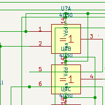
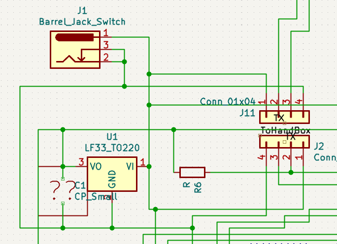
The schematic still shows an open pin and no condensers supporting the power rails. (This might work sometimes but can give you very strange results from time to time. Or even destroy parts, because the voltage regulators begin to oscillate.)
What I can say, is that the TX=10 and RX=9 pins do not match your schematic. This is "quite astonishing", as in #10 you wrote: "also I checked the program and found all the pin numbers had t be changed."
There seem to be more than one serial drivers involved on the same pins? That is a bad idea. Stick to one driver!
I cannot imagine, that you will ever get this working, if you don't take your time to "slowly" debug things small step by small step.
I once had some training at work. The instructor asked: How do you eat an elephant? - With the elephant knife, cut it down to little pieces!
The trick is to cut to really small separate pieces. So to test a serial connection, write an absolute minimum program to send one single code. After success you have one firm foundation for your project. To do small steps is rewarding, because you often have a little progress towards your big goal.
The archive function of the tool is very handy for this, because you can preserve variants of files. You also need a writeup to preserve what you did and what the result was.
So, once again I probably invested more time for this answer, than you took to send the question and "some" information.
Christof
The archive function of the tool is very handy for this,
Propeller Tool won't create an archive from a program that doesn't compile, and I suspect that is the issue here. The code is a really big mess.
@bbrien You'd have been done with this ages ago had you just written down -- in plain English, not janky code -- what you want your programs to do. Put your requirements in a document (e.g., PDF), and attach it to a post. Don't make those who could help you wade back through dozens of posts trying to figure out what you want.
Your document should include
"Big picture" description
Inputs (e.g, buttons, switches, pots, etc.)
Outputs (e.g., LEDs, motors)
Specific processes (how do you want your inputs to operate)
Protocol description for serial data
Writing a good specification is hard work, but will be worth it in the end if you can get a working telescope control out of it.
These will hopefully help you compile the program, and also explain the rest of the system. Also I sent an early attempt on the drawing but I redid that drawing and triple checked and I believe it is correct. I'll get back to you later.
What I need in these programs is a large numbers of operations .
1; Two stepper motors, 40mm in size oat 6volts, <200ma, unknown gear ratio. 2; Ability to run at multiple speeds controlled by remote switches also controlled by a computer using using optical isolators(Photo-transistors).
3; I will use Stepper Drivers based on Cd4030 and CD4027 drivingL293D drivers.
4; Hand controller will handle direction and speed by switches and a state machine
5; Mount unit will control pulse and direction for motors and include the ability to use a guide camera controlled by a separate comp. running a guiding program.
6; Motor speed will be indicated by leds in the Hand controller. and finally the communication by one way serial(hand box to mount.
Hi @bbrien ,
are you really sure, that your modified schematic, now with different serial pins 9+10, is showing the reality?
I would be very astonished, that you have some LEDs lighting.... There are also still capacitors missing (look at the datasheets!) and also the pin is still open. This won't work.
In a hurry????
You have now sent a ZIP of some other sender file, which looks much cleaner, but has totally different pin numbers.
The receiver program, that you sent in #116, on the other hand uses a totally different kind of coding for the serial information: Speed and direction are coded into the nibbles of a single byte.
So you have probably had a different sender program for this receiver?!
As we forum members have only got the information, that you send over, this information has to be absolutely consistent and reliable! For example my comment, that your schematic pin numbers don't match your program seems to be a total waste of my time. And you do not even apologise.
I am sorry, but if you don't take your time yourself, it would only be possible to help you, if you would send your hardware to someone willing to do this project for you.
Jon's idea of a writeup would be very helpful for yourself I think. You could check reality of schematic and programs against it. For example you could compare the protocol between sender and receiver with the intention.
Hi @bbrien ,
so I was curious, if I could use this tool https://forums.parallax.com/discussion/156347/improved-gear-emulator/p3 to try out your receiver "Telescope mount bs19.spin" .
The tool allows to simulate the code very slowly and to connect two virtual terminals, one for debugging and one for the serial connection. I also had a closer look at the encoding of the command from the sender.
Some result is, that it does react to commands received on pins 5/6 and also outputs debug information at 30/31.
The encoding scheme is: $30+speed<<4+direction; Speed is 0...3 and direction is 1, 2, 4, or 8. This gives "A" for 1 North, "B" for 1 South, "D" for 1 West, "H" for 1 East. "Q" for 2 North
See here for the codes: https://www.torsten-horn.de/techdocs/ascii.htm
You really need to find the sender program, which does use this encoding!
Christof
OK,
got the GEAR simulator working also for the sender and tested with NORTH and SOUTH buttons, which both send the correct code. So these two files here in this post do compile and should work together regarding protocol.
I added some greeting text on the serial lines, always a good idea to be sure that serial works.
A) First step is now to load the sender onto the handbox and make sure with a terminal on pins 30/31 that the buttons work.
B ) Check with an oscilloscope on pin 10, that there is output from the serial line.
C) Check with an oscilloscope on pin 5 of the receiver, that there is input from the serial line.
D) When C works next step is to load the receiver onto the mount box and make sure with a terminal on pins 30/31 that the codes are received.
This was work for a few hours.
Good luck, Christof


Comments
One of the nice things about programming a value is you don't have to use different variable names to represent data.
int Rspeed[] = {10, 20, 30, 80}; // <---speed or pulse per seconds. int Dspeed[] = {8, 20, 30, 80}; // <---speed or pulse per seconds.This represents the 4 mode speeds that you want to feed to the motors. Mode 0 is 10, 1 is 20, 2 is 30 and 3 is 80.
Now if you find the motors are moving to fast or slow you can change these value to a smaller or larger number instead of changing the code that is working.
I changed them to a smaller value so that you can see the LEDs blink which may not be right for the motors.
Mike
That doesn't answer my question , I still have an error at that point.
What error, with what code. All the code in the example I provided compiled without errors and worked as shown in the video.
To run the code all you needed to do was download the zip file and extract all the contents.
Mike
At first couldn't get code to upload into sinpleIDE so typed it and found errors, must something wrong with compiler , but I found codes in IDE folder and brought up codes in IDE aplication and uploaded codes into respective devices. happy to say it all works now but i need to change case 'X' to include a pulsed signal when all buttons are at 0 state.
Makes no sense since a pulsed signal at all stop would me the motors continue to run uncontrolled.
Mike
Actually it does make sense since when one is not manually controlling such as slewing or on auto guiding the scope still has to continue moving at the sidereal speed which still has to be determined( approximate 10 - 13 Hz).
I thought that's what a Guide Camera was for.
The software is not capable of doing sidereal.
Mike
I think it is possible if I remove the void checkButtons routine replace ckeckGuider routine which is an older routine which has the defaultstatement (RmotorPin, 0, 10)
(DmotorPin, 1, 0 )
high(RDirPin)
low (DDirPin)
Actually the method didn't work so reinstalled the program you gave me but I changed the case 'X' to set output on the R channel to a pulse of 8 and high on dir pin , only problem is with the start. I want the 'X' line to run on start up. How do I do that? I always have to press a button to start.
The X code should set the direction of movement before you start moving the motor.
      case 'X':
        low(DdirPin);
        high(RdirPin);
        square_wave(RmotorPin, 0, 6);
After the fdserial_open code add the following 3 lines.
After the while(1) remove the "i = 0;" statement. It is not needed.
The code should look like this:
  fd = fdserial_open(FDrx, FDtx, 0, 115200);

  Buffer[0] = '0';
  Buffer[1] = 'X';
  i = 3;

  while(1)
  {
    /**
Mike
bbrien,
You can assign a value to a variable when it's declared.
C allows an optional DEFAULT case but I am not sure if Propeller C supports it.
@Genetix ,
While that is true, in this case the preceding logic overwrites that value.
Mike
Actually one can use a DSLR camera on almost any sized scope if one has the correct adapters. I have used on my 10 inch Newtonian, Six inch Newtonian, $ inch Cassagrain, and my 10 inch Schmidt-cassagrain scope. Still haven't got the DUAL Stepper program to work.
The Cure for stuff that "doesn't work"?
BASIC

What "basic " are you referring to.
FlexBasic...stuff just works
I still love PropBASIC for the P1 also (search the forum). It has built-in serial comm's and again, they simply just do what they're told...child's play.
I spend my time doing stuff not figuring out how to do it.
Craig
I am still having problems with transmitting data from one prop to another. I pulled an old file that was given to me to test the fdserial by Digital Bob. In PUB start the second "cognew" is commented out. I remove the " ' " and try to load to memory and get an error "expected an
expression term" can someone help. want to try switches to see if working.
Things to check:
You code is really janky, and the use of cogs unnecessary. Starting and stopping the serial cog inside another cog is particularly unnecessary.
In the attached demo I'm sharing my minimalist serial driver (jm_fds_min.spin) that I use for device-to-device coms that don't require fancy formatting -- just raw bytes and strings, and True mode serial only (no inverted or open modes). There are two instances started by the main cog. Note that the TX/RX pairs are cross-connected (this is a great thing about the P1: one cog can use a pin to talk to another cog). The com1 TX pin is the same as the com2 RX pin (and vice versa). This very simple demo shows the comx objects talking to each other without any problems.
com1.str(string("Hello from COM1", 13)) ' seed the ping-pong process com1.txflush repeat if (com1.available) repeat b := com1.rxtime(2) if (b => 0) term.tx(b) else quit com1.str(string("Hello from COM1", 13)) com1.txflush time.pause(250) if (com2.available) repeat b := com2.rxtime(2) if (b => 0) term.tx(b) else quit com2.str(string(" Hello from COM2", 13)) com2.txflush time.pause(250)Hey Jon, I seem to have forgotten, in my old age, how to capture the screen shots of my program errors and of my terminal monitor views. Can you please refresh my memory, thanx. also I checked the program and found all the pin numbers had t be changed. Will check again tomorrow.
Thank You
Please Help; I using the Telescope1Master program which is a combination of the two programs"scope1master" and Serial Prop to Prop Master for the debug routine. when testing the hand box the leds work proper, but the serial does not . No output on the monitor and no com on the tx pin. Including whole schematics. Hope you can help. Am short on time.
Hi short-on-time-bbrien,
are these files the right ones?
I cannot compile the Telescope1Master.spin, as there are files missing. - There is the archive function in the tool to help here!!!
And we don't know how your receiving file might look like, as you didn't have the time to send it.
Also you did not have the time to convert the schematic to a format, that is directly visible like a picture format or pdf.
As I have learned that you use KiCad I was able to open the file.
The schematic still shows an open pin and no condensers supporting the power rails. (This might work sometimes but can give you very strange results from time to time. Or even destroy parts, because the voltage regulators begin to oscillate.)
What I can say, is that the TX=10 and RX=9 pins do not match your schematic. This is "quite astonishing", as in #10 you wrote: "also I checked the program and found all the pin numbers had t be changed."
There seem to be more than one serial drivers involved on the same pins? That is a bad idea. Stick to one driver!
I cannot imagine, that you will ever get this working, if you don't take your time to "slowly" debug things small step by small step.
I once had some training at work. The instructor asked: How do you eat an elephant? - With the elephant knife, cut it down to little pieces!
The trick is to cut to really small separate pieces. So to test a serial connection, write an absolute minimum program to send one single code. After success you have one firm foundation for your project. To do small steps is rewarding, because you often have a little progress towards your big goal.
The archive function of the tool is very handy for this, because you can preserve variants of files. You also need a writeup to preserve what you did and what the result was.
So, once again I probably invested more time for this answer, than you took to send the question and "some" information.
Christof
Propeller Tool won't create an archive from a program that doesn't compile, and I suspect that is the issue here. The code is a really big mess.
@bbrien You'd have been done with this ages ago had you just written down -- in plain English, not janky code -- what you want your programs to do. Put your requirements in a document (e.g., PDF), and attach it to a post. Don't make those who could help you wade back through dozens of posts trying to figure out what you want.
Your document should include
Writing a good specification is hard work, but will be worth it in the end if you can get a working telescope control out of it.
These will hopefully help you compile the program, and also explain the rest of the system. Also I sent an early attempt on the drawing but I redid that drawing and triple checked and I believe it is correct. I'll get back to you later.
What I need in these programs is a large numbers of operations .
1; Two stepper motors, 40mm in size oat 6volts, <200ma, unknown gear ratio. 2; Ability to run at multiple speeds controlled by remote switches also controlled by a computer using using optical isolators(Photo-transistors).
3; I will use Stepper Drivers based on Cd4030 and CD4027 drivingL293D drivers.
4; Hand controller will handle direction and speed by switches and a state machine
5; Mount unit will control pulse and direction for motors and include the ability to use a guide camera controlled by a separate comp. running a guiding program.
6; Motor speed will be indicated by leds in the Hand controller. and finally the communication by one way serial(hand box to mount.
Hi @bbrien ,
are you really sure, that your modified schematic, now with different serial pins 9+10, is showing the reality?
I would be very astonished, that you have some LEDs lighting....
There are also still capacitors missing (look at the datasheets!) and also the pin is still open. This won't work.
In a hurry????
You have now sent a ZIP of some other sender file, which looks much cleaner, but has totally different pin numbers.
The receiver program, that you sent in #116, on the other hand uses a totally different kind of coding for the serial information: Speed and direction are coded into the nibbles of a single byte.
So you have probably had a different sender program for this receiver?!
As we forum members have only got the information, that you send over, this information has to be absolutely consistent and reliable! For example my comment, that your schematic pin numbers don't match your program seems to be a total waste of my time. And you do not even apologise.
I am sorry, but if you don't take your time yourself, it would only be possible to help you, if you would send your hardware to someone willing to do this project for you.
Jon's idea of a writeup would be very helpful for yourself I think. You could check reality of schematic and programs against it. For example you could compare the protocol between sender and receiver with the intention.
Christof
Hi @bbrien ,
so I was curious, if I could use this tool https://forums.parallax.com/discussion/156347/improved-gear-emulator/p3 to try out your receiver "Telescope mount bs19.spin" .
The tool allows to simulate the code very slowly and to connect two virtual terminals, one for debugging and one for the serial connection. I also had a closer look at the encoding of the command from the sender.
Some result is, that it does react to commands received on pins 5/6 and also outputs debug information at 30/31.
The encoding scheme is: $30+speed<<4+direction; Speed is 0...3 and direction is 1, 2, 4, or 8. This gives "A" for 1 North, "B" for 1 South, "D" for 1 West, "H" for 1 East. "Q" for 2 North
See here for the codes: https://www.torsten-horn.de/techdocs/ascii.htm
You really need to find the sender program, which does use this encoding!
Christof
Aha: "Telescope handbox dh9-A1.spin" from post #117 here: https://forums.parallax.com/discussion/173757/dual-stepper-motors/p4
seems to use the encoding. Please check: Is this the right sender?
Christof
OK,
got the GEAR simulator working also for the sender and tested with NORTH and SOUTH buttons, which both send the correct code. So these two files here in this post do compile and should work together regarding protocol.
I added some greeting text on the serial lines, always a good idea to be sure that serial works.
A) First step is now to load the sender onto the handbox and make sure with a terminal on pins 30/31 that the buttons work.
B ) Check with an oscilloscope on pin 10, that there is output from the serial line.
C) Check with an oscilloscope on pin 5 of the receiver, that there is input from the serial line.
D) When C works next step is to load the receiver onto the mount box and make sure with a terminal on pins 30/31 that the codes are received.
This was work for a few hours.
Good luck, Christof