

Servo motor question
 T Chap
Posts: 4,260
T Chap
Posts: 4,260
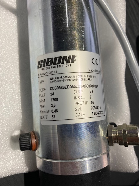
I have never used a servo motor like this one being drive from a PLC and trying bye help someone out. They sent these photos. I use my own prop 1 PID loop and brushless motor/hall/encoder for most projects. How possible is it to convert a direction and speed(PWM output) from prop 1 on a BLDC motor driver to a modified version with an H bridge (2 mosfets high and 2 low) and not have to do much else to make this servo motor move to an encoder position? The PID loop is more of a Proportional with some integral chasing the error of the current encoder position - new position. Seems like it should just work the same. The motor shown has a similar encoder scheme to mine and only 2 wires to to the motor. I’m trying to learn why my bldc with PID and encoders which is extremely precise moving to a position would be any different from 3 wire brushless with hall sensors on to 2 wire DC motor . I want to get rid of the PLC. 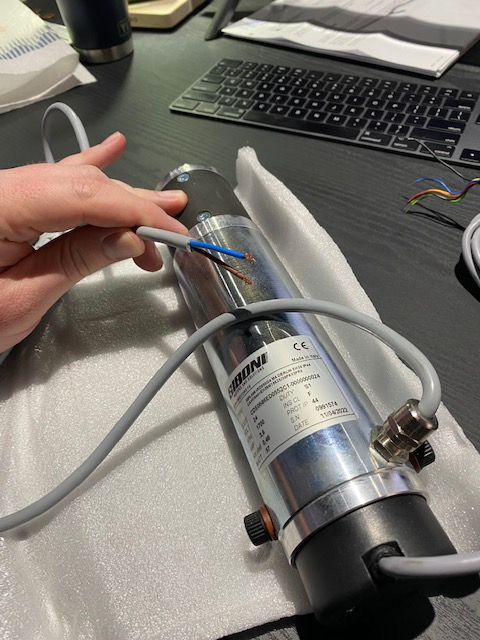
Comments
Be careful about your wishes vs the customers wishes:
The Italian company making these systems can’t get PLCs for many months. The US company selling the systems have many problems and can’t get them to work often and time difference is a big issue to get support. They want an alternative that just works. it’s not factory use. It’s some specialized bullet proof door for some application. Nobody domestically can figure yes plc out without guys on the phone with Italy. They cant get any diagnostics out of it When it fails they can only get on the phones.
Cool. Good to know. Yes, PLCs get misused too - Putting passwords on them for example.
You should still be able to use the existing motor drives though.
3.6A might be pushing-it a bit for the LMD18200 H-bridge which is rated for 3A continuous. Might be down to cooling, though.
I use this device all the time for my test-rig motors and driving bang-bang hydraulic solenoid-valves. Pretty cool getting flow control out of a valve that wasn't designed for it (PWM).
The LMD18200 provides two options; PWM+Dir or (my preference) locked anti-phase PWM where 50% duty-cycle = null.
Unless you are dealing with something really docile, I don't see you getting away without the D-term, though. It's the velocity damper and without it, you'll have overshoot/instability.
I don't even allow the integrator into the equation until the motor is steady-state.
I recently picked-up a few of the Chinese modules, out of curiosity and deliberately proceeded to attempt to destroy them. Surprisingly, they seem to faithfully follow the datasheet spec when it comes to overcurrent and over-temp auto-shutdown. Wasn't able to realise any white smoke at all.
Did the same with an L298 version and I smoked it in a heartbeat.
Actually, though; a genuine L298 might be a viable option because this 2-motor driver can be hooked-up in parallel to drive a single brushed motor. Only thing that I don't like (there might be a workaround) is that it requires separate direction signals (+ AND -) along with the PWM input.
LMD18200 is still my favorite
Craig
Edit: Just did a search for LMD1800 module and this came up as an alternative:
https://www.ebay.com/itm/373656775219
And worse than that. The internal maintenance electrician who secretly programs a time-bomb. Line goes down, company in a panic and he's the "hero" who always gets the line up and running. Works really well come review time because he is their "computer wizard"
Craig
I hear stories, not even anecdotal, but I've never struck such persons myself.
Oh it happens a lot . Human nature. How many manufacturers employ only a single maintenance guy.
It's one of my pet peeves with PLCs.
The other one is H&S. They can easily inspect/test machine guarding but the maintenance guy who has just figured-out how to make changes in a machine control program....who verifies that he hasn't just made the machine a potential death trap?
Craig
Must be a different nature. EDIT: A case of you get what you're expecting to get, maybe.
Italy....Would be exactly the same if they were in the same time-zone
The only thing that has any urgency over there is lunch!
Craig
I forgot about the Universal Motor Driver. It can handle two brushed motors:
https://www.parallax.com/product/universal-motor-driver-p2-add-on-board/
Thanks for the suggestions above! Will check those out.
Today a US guy had to export a text error log from the PLC, email it to italy, wait for a reply. Bad encoder. Took days to solve what should have been seconds on an LCD "bad encoder". My systems would show which pin (or both ) of the encoder that were not toggling.
I answered my own questions about modding the BLDC. I use MC33035 BLDC driver IC going into a 6 channel mosfet driver HIP4086. I just studied the truth table on the Hall sensor inputs and found a combination where I can set the hall sensor inputs to a fixed value. Only change the F/R ( direction pin) to flip the motor. Connect a DC motor 2 wires to Top/Bottom sets A and C. Removed Top side mosfet B just to be safe. It works perfectly to drive the DC, same behavior as driving the BLDC motor. The input to the MC33035 is a rigged up method of 0 - 3v3 from the Prop through an Opto fet voltage divider and CTRA. I still don't fully understand what a servo system is that's different from what I have for simple projects. My PID chases the encoder error VS position and locks the motor/encoder to that position precisely.
Not sure I comprehend but if you are working with a "Servo drive" that was driven by the PLC then that will most likely be configured "velocity mode".
Your motor command is merely a velocity reference and the drive will be handling the regulation (internal PID)
"Torque mode" is when the drive is merely a transcondutance device. Your motor command results in a proportional current output which is when the full PID becomes the responsibility of the controller.
I have always used torque mode because I don't want to involve an external loop.
Limiting motor torque means simply limiting the PID output instead of some external analog signal to the drive.
I have come across PLC "motion control" and it is usually limited to the basics.
Craig
PLCs don't do text logs, I suspect it isn't really a PLC at all. Sounds like just an ordinary embedded controller.
Eek, I just realised you're also trying to replace the motors are well! Why so much effort?
You have no trajectory profiler (acceleration/slew/deceleration)? You just leap from actual position to commanded position?
Craig
No I definitely create a profile. ramp up, ramp down, very elegant. But I wouldn't this scheme for sycning multi axis cnc. Doors and widow and other home automation is fine with single motors. The PID follows closely to the profile being generated but theres some slight lag which is irrelevant, the final positions are very precise.
I may not replace the motors, that's why I'm exploring using my own BLDC motor board as a 2 wire brush motor using the scheme I came up with above. Versus finding a new Hbridge and having to build a new PCB for it. Just exploring options.
The method that I employ: