

Universal Motor Driver - Dual wheel steering, motor control, and position tracking Objects for P2
 Stephen Moraco
Posts: 476
Stephen Moraco
Posts: 476
I've just released v1.0.1 of our new BLDC Motor drivers.
Initial Public Release
BLDC Motor Driver with steering and position tracking.
- Full dual motor control of robotic platform using 6.5" hoverboard BLDC wheels from Parallax and their BLDC Motor control boards.
Initially, this is available from the releases section of the official repository (it may eventually be added to the p2 obex.)
There is a wealth of information at the project repository so please review the content of the first page as well as the "Additional pages" cited in the table of contents on the first page.
See the Add to your own project page for download and setup instructions.
If you want an easy low-cost platform for a two-wheeled bot (You saw the one I have in the video at one of our P2LFs) I have design files at the repo and, here in the US, you can order from Send-Cut-Send a ¼" thick MDF platform, laser-cut, with height spacers for wheels (to get the castors raised) all for under $35 shipped. The platform also has laser-cut mounting holes for the wheels, the castors, and the Mini-Edge Breakout board with motor boards attached.
From this point forward let's use the github repository issues page for reporting real issues with the use or requesting features. Let's use this forum thread for any general discussion of this capability.
I look forward to hearing what you think of the usability of the new steering and drive control interface for these objects.
Oh, and yes, a draft version of the FlySky R/C control of the platform is provided as one of the demos!
Have fun!
Comments
Thanks for this. Hopefully I can find time for my project. I want to repower one of my antique garden tractors with a hoverboard motor.
Now THAT is a visual collage and mental whiplash all in one!")
Pictures or it never happened.
Be patient for those pictures, lol. It's a Choremaster from the late 40's or 50's. The original engine was 2 hp. I have a 3 hp predator now. It's too light to get the power to the ground. So a hoverboard motor should be plenty.
... and we now have v1.1.0 of our new BLDC Motor drivers.
currently, this is available from the releases section of the official repository (it will be added to the p2 obex.)
See the Add to your own project page for download and setup instructions.
For a quick review of the Motor and Steering interfaces see the page P2-BLDC-Motor-Control - Drive Objects.
I look forward to hearing what you think of the usability of these steering and drive control objects.
Have fun!
NEW v2.0.0 of our new BLDC Motor drivers.
currently, this is available from the releases section of the official repository (it will be added to the p2 obex.)
(P2 Obex contains the v1.1.0 release at the moment.)
See the P2-BLDC-Motor-Control - Via Serial from RPi, Arduino, or... page for the system diagram, download, and setup instructions.
See YouTube Control our 2-wheel BLDC robot platform from an RPi for a demo of how the system works on my platform.
See The Authors' Test Platform for details of my platform.
For a quick review of the Serial Steering interface see the page Serial Interface of Steering Object.
I look forward to hearing what you think of this new capability.
Have fun!
NEW v2.1.0 of our new BLDC Motor driver.
LEFT: 6.5" hub motor SKU 27860 | RIGHT: new smaller motor with DocoEng.com label. SKU 750-90020
currently, this is available from the releases section of the official repository (it will be added to the p2 obex.)
Two additional .zip files are available from the Assets section of the release page:
(P2 Obex contains the v1.1.0 release at the moment.)
See the Configuring the driver for your motor page for details about the available motors and how to select one in your code.
See the P2-BLDC-Motor-Control - Via Serial from RPi, Arduino, or... page for the system diagram, download, and setup instructions.
See YouTube Control our 2-wheel BLDC robot platform from an RPi for a demo of how the system works on my platform.
See The Authors' Test Platform for details of my platform.
For a quick review of the Serial Steering interface see the page Serial Interface of Steering Object.
Have fun!
For the BLDC motor driver is there any way to disable that "protection diode" or an alternate drop in part that doesn't have it? I would like to experiment with dumping the back EMF into charging a secondary battery instead of wasting it through the "protection diode".
Te protection diode doesn't dissipate the energy but feeds it back to the dc-link capacitor, so no need to try something else..
NEW v3.0.0 of our BLDC Motor driver.
currently, this is available from the releases section of the official repository (it will be added to the p2 obex.)
Two additional .zip files are available from the Assets section of the release page:
(P2 Obex contains the v1.1.0 release at the moment.)
See the Configuring the driver for your motor page for details about the available motors and how to select one in your code.
See the P2-BLDC-Motor-Control - Via Serial from RPi, Arduino, or... page for the system diagram, download, and setup instructions.
See YouTube Control our 2-wheel BLDC robot platform from an RPi for a demo of how the system works on my platform.
See The Authors' Test Platform for details of my platform.
For a quick review of the Serial Steering interface see the page Serial Interface of Steering Object.
Have fun!
@"Stephen Moraco"
@"Ken Gracey"
Hello,
I took a simple look at this project. Where to the hall sensors connect. I am interested in learning the DIH23-30-013Z BLDC that I have.
The module may help me.
Thanks
Martin
Hi @pilot0315
The Parallax 64010 universal motor driver board has a standard 0.1" header for the hall sensors. It accepts the connector that is pre-wired on the large 6.5" hub wheels.
For other motors that might not have the connector, you'd usually wire them: 5V=red, GND=black, and the UVW pins go to the three other color cables in the same order as attached to the motor power/phase connectors. (So taking the image as an example, U=Yellow, V=Blue, W=Green).
https://www.parallax.com/product/universal-motor-driver-p2-add-on-board/
@pilot0315 contact me when you get the hardware. I looked at the motor specs and have a rough idea of what you will need to do to the driver to add support for this motor.
If you are interested we can discuss it as you are working on it. The idea would be that once you have it working we merge the code into the repo so others can then select this motor.
@VonSzarvas
Thanks for the information.
@"Stephen Moraco"
Thanks for the information.
WARNING, WARNING, WARNING:
@pilot0315 I just wanted to leave a quick heads up regarding the protection of your time.
Adding a new motor to the driver is, NOT an easy thing to do. Please do not entertain the idea if you are not willing to take on a multi-week project. It's a complex effort. It requires studying and then experimenting with the motor. Once the motor is better understood then it takes time to characterize the motor under the different power levels we support. Then we add configuration selection, new configuration limits for the motor, and possibly new drive tables for the new motor.
Tools one would need would be a: (1) Benchtop power supply capable of providing the voltages we support at the amount of current the motor needs, (2) a logic analyzer capable of running at P2 speeds with a good capture depth: I'm running 250 MHz capture rate at 20 seconds capture depth at times to evaluate what's happening. I'm also using (3) an HDMI display for runtime output of the exercising/characterization code, and lastly, I'm using (4) a scope to monitor the hall sensors and pwm /voltages we are feeding to the motor.
Oh and lastly there is also the risk of regression. When we add a new motor we have to go back and recertify all the prior motors so we can ascertain that we haven't affected the operation of one of the prior supported motors.
So, while I'm eager to work with someone else who's willing to take on such an effort (so I don't have to do this for all the motors we support) I really want a person who is sincere about committing to this level of effort. Driving these motors is complex enough that it really does take an investment in studying the code and the new motor. And just to state "one last time"... Adding a new motor to work with the driver is NOT an easy or lightweight project. Please don't expect it to be quick or easy.
end of WARNING, WARNING, WARNING
@"Stephen Moraco"
Dumb question?
I took a quick look at your code. I would like to see the basic code that runs the motor. I am an old programmer on the IBM 1130 and 360 , HP 2000 from the old days. I got to see it for myself so as to understand it. The I like to play.
Thanks in advance.
Martin.
FYI I ordered the motor interface.
https://github.com/ironsheep/P2-BLDC-Motor-Control/blob/main/src/demo_single_motor.spin2
@"Stephen Moraco"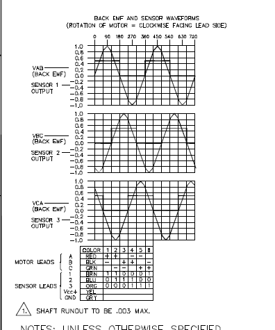
Hello,
I set up the bldc with the board today. Having watched the quickbyte and following the instructions I got half a rotation each time I initiated the program. Changed the power leads to make sure I got them correct. My basic question is that in the video with the motor used there he mentioned the hall sensor wire colors corresponding to W V and U. I made an assumption with the data sheet as they number them, 1 2 3 as corresponding to the A B C. Any suggestions. I am uploading the data sheet and picture of the wire colors.
Thanks
@pilot0315 I can guarantee that the driver will not work with that motor until adjustments are made to built-in tables and power limits. There will be a number of experiments to determine what needs to be added.
Did you wander across my page introducing the concepts we need for adding a new motor?
@pilot0315 - I think you have the phase relationship correct, or else the motor wouldn't turn at all.
That said, just something to be aware of with SOME motors, you can't always go by the color code and matching of the color code between the UVW of the motor and the UVW of the hall sensors.
For instance in the case of one of our motors, the phase color for the motor was (Green, Yellow, Blue) and the hall sensors used the same color scheme but Green did not go to Green, Yellow not to Yellow, and Blue not to Blue.... Instead Green went to Yellow, Yellow went to Blue, and Blue went to Green.
Always important to study the datasheet
Notice (below): The Motor Power interface vs. the Hall Sensor interface
@"Beau Schwabe"
Great to hear from you. I will look at this. I am going to try a different power supply and up the voltage a bit.
Hi,
being curious, I had a look at the source code of the low level PASM motor driver. In my opinion, it would make sense to have some explaining document, how this works! With this, people could add their own motor to the system more easily.
((( The "Attainable RPM at Power" chart, which makes no sense, seems to indicate, that there is something wrong at this low level for the small motor.
https://github.com/ironsheep/P2-BLDC-Motor-Control/blob/main/MOTOR_CHOICE.md )))
sense_i_ seems not to be used at all? (No protection here?)
The measured voltages of the coils sense_u/w/v_ seem not to be used? (Would be difficult without switching off the current during measurement?)
The datasheet value for back emf constant is not used. ((( The given value on https://parallax.com/product/motor-bldc-24v-4000-rpm/ should be corrected. There is no data of the maximum allowed current? Is this 1.8A.eff? )))
The angle between the rotor and the field seems to be constant?
duty_ is the coil amplitude voltage and is corrected by the integral of the deviation of the position? So this is a position controlled system? ((( Perhaps a speed controlled duty_ would be more easy to adapt at this low level? )))
So all-in-all for a different motor after correct connection with this driver on the lowest level you would need to check or adjust the angle(s) between the hall sensors and the coils. I think that duty_up and duty_dn and the ramp constants are dependant from the system too on a higher level.
Edit: Freescale/NXP have nice application notes: https://nxp.com/docs/en/application-note/AN4776.pdf and https://nxp.com/docs/en/application-note/AN4413.pdf These are speed controlled. And the second has a linear ramp of the pwm voltage instead of sine.
@"Christof Eb." We are at an early release with this project.
The timeline is:
Yes, a document was started but I'm just not there yet. It turns out that until I added the 2nd motor even I didn't know what we'd need in that document. Since I'm learning the driver as well.
I'm working hurriedly on a new project for demo during our upcoming live forum (Wed.) but I will try to get the essentials added to my "how to add" page over the next couple of nights after I finish my engineering days.
I'll post again here as I get more content added.
I appreciate the interest and I'll work to support your interest... you all are just ahead of the curve here.")
@pilot0315 , @"Christof Eb." and @"Beau Schwabe"
Ok, I've added initial content to provide more specifics on adding a new motor to the driver. This should help. Please let me know if you see something obvious that's missing. See updates at my repo
I'm returning now to figuring out why my hardware is not yet working... Live Forum imminent... no pressure... ;-)
Hi, Stephen,
some documentation, which explains how the low level PASM driver in https://github.com/ironsheep/P2-BLDC-Motor-Control/blob/main/src/isp_bldc_motor.spin2 works, was what I meant. For example I don't understand, why all 6 outputs have always PWM. (As far as I understand this code) This is contrary to Figure 18 in https://nxp.com/docs/en/application-note/AN4413.pdf, where Q4 is always ( during that phase) on, allowing the freewheeling inductance current go to GND. One of the other things, that I don't understand is, how angle_ is corrected by the hall signals. This seems to be a integrating method using offset_fwd_ ? _ I could imagine, that this can make trouble.
I still assume, that duty_up and duty_dn is likely to be adjusted for a new application, because these are the main I-constants. (???)
Christof
@"Stephen Moraco"
@"Beau Schwabe"
I got the Mystery Box and what a surprise!!!!!!
A Doco bldc, a Universal motor driver and a hdmi add on board.
Set it up and wow all works. Tried my motor again (both at 24 volts) Doco good. My motor still partial turns.
Will now use your techniques and checkout the Hall's May have to switch them.
Let you know.
Thanks
@"Stephen Moraco" I noticed on your gitHub page, ironsheep /P2-BLDC-Motor-Control , you're using the HRB 5S 18.5V 5000mAh 50-100C RC Lipo Battery for your robot. I need to purchase a battery for my Mystery Box. That one seemed a little pricey. But I could use it on other projects as well. I just wanted to check and see how it was working out for you before I went and bought one.
I'm happy with how it's working. I don't have any long hours running it but it's been great for all my testing.
@CJMJ
@"Stephen Moraco"
I am using two different power supplies one is variable to 20 volts the other is 24 volts. Easier than a battery for the experiments. Motor and supplies do not seem to complain.
Martin
@pilot0315 Care to share which two you are looking at?