@evanh said:
And if the diagram has anything correct then that is saying outputs transition on falling REFCLK.
The datasheet of the LAN8720 defines timing requirements relative to the rising edge of REFCLK. Actually it doesn't matter where the exact change of the data lines occur as long as they settle at least the min. setup time before the next clock and stay valid for at least the min. hold time after.
Synchronizing the data lines to the falling edge of the clock is often done so that hold time requirements or small timing variations don't matter. It's also better to visualize on the scope or in datasheet diagrams because it clearly shows that data must be stable at the rising edge.
Oh, I guess it doesn't matter if TX_EN rises later. The preamble isn't a defined length is it. That's why SFD detection has to be accepted at any bit position.
The problem with widely spread standards is that there are a lot of different designs out there with differing tolerances for abuse and non-standard behaviour. We should stick to the standard as close as possible and not rely on others tolerating "bending" of the rules. So it woldn't be a good idea to send a preamble with a different length as 64 bits. I also wouldn't send zero bits before the preamble. But all data before TX_EN goes high is safely ignored by the LAN8720 so it doesn't matter when the packet starts relative to the smart pin shift register boundaries as long as TX_EN and TXD0/1 are synchronized to each other.
Some more thoughts about clock frequencies and using the streamer:
100MHz might be possible. That would be 320ns or 32 clocks per longword of data. However, I've never seen somebody running the P2 at such a low frequency. Ok, if you need to save battery power... but then having wired Ethernet doesn't make sense. You could use Wifi or PoE instead.
The odd multiples like 150 or 250MHz might also work. We need NCO dividers for the streamer but that doesn't cause problems. If we restart the streamer for each packet with XINIT/XZERO no rollover should ever happen before the packet is finished. For the 50MHz clock output a smart pin PWM output is better than an NCO output because odd or non-power-of-two divider ratios are possible without rounding errors. However, the 50MHz square wave for 150:3 would have a 33/67% duty cycle and the 250:5 would have 40/60%. The data sheet specifies a 40/60 to 60/40 range. Also, if we use the REFCLK pin as smart pin output that would disable the trick to simultanously monitor the CRS_DV signal with the +3 input selector.
I'm still struggeling a bit with the TX code. The silicon docs are a bit vague (as often...) about what happens if a buffer underrun occurs at smart pin in P_SYNC_TX mode. I thought it would just repeat the last bit and continue immediately when a new word is written to the buffer. But re-starting the shifter causes some timing hickups. I think I have to reset the smart pins at the beginning of each packet to get well defined startup conditions. That adds some more special cases to my already complex code to handle the 0..3 byte problem at the beginning of the packet.
I wonder what would happen if I connect a DIY loopback cable that simply shorts the 1-2 pair to the 3-6 pair. Will the PHY auto-negotiate with itself? Otherwise I have to turn off auto-negotiation or use the internal loopback mode.... Ah! Just discovered: 3.8.8.3 Connector Loopback is explicitely mentioned in the data sheet. That is useful for analyzing packets with bad checksum or bad length. At the PC side I'll never see such packets because the network interface discards them in hardware.
@ManAtWork said:
... and continue immediately when a new word is written to the buffer. But re-starting the shifter causes some timing hickups. I think I have to reset the smart pins at the beginning of each packet to get well defined startup conditions.
You'll want to set bit5 of parameter to WXPIN. Then it'll respond immediately when empty. Without that it always buffers before moving to shifter.
@evanh said:
You'll want to set bit5 of parameter to WXPIN. Then it'll respond immediately when empty. Without that it always buffers before moving to shifter.
Ah, good to know. I thought I had to use mode bit5=0 because the docs say something about continous vs. start/stop mode and we have a continous clock. But the actual problem was that the IN signal does not mean "bufffer empty / ready for wypin" but instead is not activated after the second wypin (first after DIR=h) AND the buffer becoming empty again. I've finally got it to work with continous clock mode. Don't know if bit5=1 mode would save some instructions.
Some further progress... My transmit code now calculates the same CRCs as I have received from a PC. Strange thing is that the CRC has to be byte reversed and inverted. On the reciver side this is not necesssary. Ok, I've also inverted the final "magic" value found on Wiki but I consider this an arbitrary number so inverting it does just turn it into another arbitrary number. Bytes are stored in the same order as they are shifted into the smart pins and the CRC, though. No byte reversal, there.
Now I only have to persuade the PC to accept packets I send.
Part of my own protocol for my CNC controllers is a simple procedure to find all connected modules. The PC sends a broadcast and all modules answer with their hardware type ID. The packet contents are all static because all counters and acknowledge bit masks that are part of the transport layer start at zero and this is the beginning of the communication. No TCP/IP stack required. Of course, Wireshark also works if you know the MAC address of the PC. Sounds easy but if it doesn't work at the first go you never know why. This is why I think a loopback cable is better to debug it.
Strange thing is that the CRC has to be byte reversed and inverted.
My fault. It needs to be inverted but not byte reversed. I was using the wrong debug command, uhex_byte_array for the data and uhex_long for the CRC. No wonder the CRC looked reversed.
I've just finished the layout of my new CNC controller board.
It is a piggyback board that will sit on top of the main board in the "B2CPU" module on the left side. The axis modules on the right side have a P1 each and are connected to the main module with a high speed serial bus.
The next step would be to implement some higher level protocol. I'm about to port the software for my CNC controller from the P1 to P2. But that won't be of much use for anybody else since the protocol is proprietary. Jesse (@avsa242) and Terry (@ke4pjw) have said that they have already made some experiments with TCP/IP or UDP.
If I remember correctly there was also a P1 project that had a TCP/IP implementation based on the ENC28J60. It was the "Thumper" internet radio by Harrison Pham. I think the Spin1 code could be ported to Spin2 without big problems but I don't know if it supports everything we need.
@ManAtWork said:
...
If I remember correctly there was also a P1 project that had a TCP/IP implementation based on the ENC28J60. It was the "Thumper" internet radio by Harrison Pham. I think the Spin1 code could be ported to Spin2 without big problems but I don't know if it supports everything we need.
I built lwip (Lightweight IP) for riscvp2. Only tried it with PPP over serial. I don't know how easy it would be to interface with a spin application. Connecting it to a spin serial driver wasn't bad. Getting it working with Ethernet isn't something I really want to spend my time on now. The version I used is probably really outdated by now. But if you're interested, you can find it at my github.
@ManAtWork , I've been writing an IP stack using your driver and accessory board. It's just barely usable for UDP, and it can do some other things such as replying to ARP requests and maintaining a local ARP cache, responding to ICMP pings, and sending TCP RST packets in response to attempts to talk to it via TCP. I'm planning on adding a DHCP client, a DNS resolver, mDNS, Zeroconf, and maybe IPv6 support.
I couldn't find a license specified in your driver - is it licensed under something like MIT? I'd like to post my work, together with a slightly modified version of your driver, on Github.
I'll start a new thread here once I upload my local repo to GitHub.
Wow, that is great news. I have already been thinking about how to motivate somebody to write an IP stack or how to coordinate experiments from different contributors so that the result would hopefully be something useful for everybody but haven't got the time. I can hardly keep my head above the flood level of work and orders since I finished the driver. But you make great progress!
Yes of course, feel free to use the driver in anyway you like. You can just add the usual MIT license banner. Have you found any bugs?
I just want to summarize the discussion about full vs. half duplex in that thread (post #11 to #16). @Electrodude said he needs full duplex but wants to optimize the driver to use less cogs.
There had been suggestions (see page #1 and #2 of this thread) to use the streamer for transmitting which would possibly free some resources so that one cog could handle receiving and transmitting at the same time. The current driver uses one cog for each task and feeds/polls the shift registers directly in software. Using the steamer for TX would require pre-computing the CRC. Receiving needs constant attention and might require an interrupt triggered by RX_DV to be able to react quickly even while transmitting is in progress. I think it's going to be tough but should be possible.
Problem is, the preamble leads directly to the beginning of the data. No time in between... so it seems at first... Maybe if we put the streamer in "manual" mode (ie. Write the stream to register X)... one could analyze the preamble and switch the streamer over to HUBwrite mode....possibly meddling with the streamer timing (eggbeater?) to align the writes, at least to write whole bytes and not half-nibbles... after the streamer is fine, patch the beginning of the packet which was torn apart... or in the worst case re-arranging the whole packets afterwards.... if i had the hardware, i might try it... i guess it would be a only small modification to the PCB)..
We might stream the whole packet to LUTram and do the crc from there and copy it to HUBram exactly where it has to be. Think towards TCP/IP where you have a serial stream of data.. and a frame that is moving along with the read and write pointers (wrapped at framesize X) ... so to do that comfortably we might have to copy the frame anyways at least once.
@Simonius said:
Problem is, the preamble leads directly to the beginning of the data. No time in between... so it seems at first...
Sorry for the confusion. In the early posts on page #1 of this thread I was also speculating about using the streamer for receiving. But it turned out that this would be really hard. It's much easier to use the streamer for transmitting because everything is predictable and the whole packet including CRC can be pre-calculated. Obviously you can't use it for both (full duplex) because there's only one streamer per cog and the FIFO can handle only one direction at a time.
LUT RAM could be used for buffering as long as no extra large packets are required (1522 byte limit).
I've not really been following this thread so this may have already been suggested but how about polled RX and streamed TX? You only initiate the TX at suitable times when you know for sure have a free cycle in the RX code and won't interfere with it, or otherwise when RX is idle. The TX CRC is precomputed prior to sending the packet out, by another client COG when it buffers it for TX. Actually it would have been really nice if the RMII COG could also do the TX CRC itself in advance using the P2's CRC instructions but this method could introduce too much instruction execution jitter due to egg-beater timing if RX work is also being done at the same time. It would likely only be doable in real RX idle time, reducing TX performance during full duplex operation. Having the client COG compute the CRC increases performance because the next outgoing CRC can be computed while transmitting and receiving other packets at the same time allowing proper full duplex operation.
For the sake of a good latency you might want to start the streamer on one COG simultaneously with the CRC of the same packet on another COG (the latter will finish before the packet is half-through)
doing CRC only in the idle time of the receiving COG will work but not while it is actually receiving (cause the FIFO is then occupied)
the latency for outgoing packets would increase dramatically with higher incoming traffic, quite hard to predict especially since network switches got relatively huge buffers nowadays that might keep our COG occupied with swathes of packets... it would be use case specific and also easy to DoS (denial of service attack)
having our In/Out duplex divided into two COGs seems appropiate, since we are on a concurrent, multi-processor system:)
I thought again, about the implications of doing RX/TX on one cog. The transfer from HUB to LUTram (for buffering) could take place in the inter-packet-gap but it would have to be quite fast.
What would be the fastest way to copy to LUTram ( how many clocks / WORD ?)
Fastest way to copy to LUT RAM from HUB is a block copy with SETQ2.
E.g.
SETQ2 len  ' actually reads len+1 longs
RDLONG 0, addr
this burst transfers at a rate of 1 P2 clock per 4 bytes read after the first read latency interval completes, although this can be affected by any parallel streamer bandwidth as well. For 100Mbps Ethernet the stolen bandwidth is only 3.125M transfers per second which is only a small component of the total hub bandwidth (at 200MHz it's less than 2% lost).
But transferring to LUT from HUB is not really of much use as you then have to read it out into COGRAM to do anything with it which takes 3 more clocks per long. Better to read directly into COGRAM (and put your executable code into LUTRAM for freeing up more space).
I was curious to see what sort of peak throughput this was capable of so extended the size of the example frame in @ManAtWork 's demo code to 1500 bytes (I just copied the txData array to a new one with byte $00[1486] after the Ethernet protocol) and sent it in a loop in TxDemo() - 6.4MBytes/sec as reported by my PC's network manager (200MHz Fsys). At 300MHz, 11.6MBytes/sec. I'd gone back to my desktop and forgotten I'd left the P2 running for awhile and noticed the sound of the fan on my laptop getting unusually loud. I switched back to it to find it was running at 82C and the fan over 3000RPMs. I shut the P2 down and watched the laptop quickly start to cool off. I suspect this was more due to Wireshark with its ever-increasing log of packets flying by, but still pretty impressive speed


Comments
The datasheet of the LAN8720 defines timing requirements relative to the rising edge of REFCLK. Actually it doesn't matter where the exact change of the data lines occur as long as they settle at least the min. setup time before the next clock and stay valid for at least the min. hold time after.
Synchronizing the data lines to the falling edge of the clock is often done so that hold time requirements or small timing variations don't matter. It's also better to visualize on the scope or in datasheet diagrams because it clearly shows that data must be stable at the rising edge.
Oh, I guess it doesn't matter if TX_EN rises later. The preamble isn't a defined length is it. That's why SFD detection has to be accepted at any bit position.
The problem with widely spread standards is that there are a lot of different designs out there with differing tolerances for abuse and non-standard behaviour. We should stick to the standard as close as possible and not rely on others tolerating "bending" of the rules. So it woldn't be a good idea to send a preamble with a different length as 64 bits. I also wouldn't send zero bits before the preamble. But all data before TX_EN goes high is safely ignored by the LAN8720 so it doesn't matter when the packet starts relative to the smart pin shift register boundaries as long as TX_EN and TXD0/1 are synchronized to each other.
Some more thoughts about clock frequencies and using the streamer:
100MHz might be possible. That would be 320ns or 32 clocks per longword of data. However, I've never seen somebody running the P2 at such a low frequency. Ok, if you need to save battery power... but then having wired Ethernet doesn't make sense. You could use Wifi or PoE instead.
The odd multiples like 150 or 250MHz might also work. We need NCO dividers for the streamer but that doesn't cause problems. If we restart the streamer for each packet with XINIT/XZERO no rollover should ever happen before the packet is finished. For the 50MHz clock output a smart pin PWM output is better than an NCO output because odd or non-power-of-two divider ratios are possible without rounding errors. However, the 50MHz square wave for 150:3 would have a 33/67% duty cycle and the 250:5 would have 40/60%. The data sheet specifies a 40/60 to 60/40 range. Also, if we use the REFCLK pin as smart pin output that would disable the trick to simultanously monitor the CRS_DV signal with the +3 input selector.
I'm still struggeling a bit with the TX code. The silicon docs are a bit vague (as often...) about what happens if a buffer underrun occurs at smart pin in P_SYNC_TX mode. I thought it would just repeat the last bit and continue immediately when a new word is written to the buffer. But re-starting the shifter causes some timing hickups. I think I have to reset the smart pins at the beginning of each packet to get well defined startup conditions. That adds some more special cases to my already complex code to handle the 0..3 byte problem at the beginning of the packet.
I wonder what would happen if I connect a DIY loopback cable that simply shorts the 1-2 pair to the 3-6 pair. Will the PHY auto-negotiate with itself? Otherwise I have to turn off auto-negotiation or use the internal loopback mode.... Ah! Just discovered: 3.8.8.3 Connector Loopback is explicitely mentioned in the data sheet. That is useful for analyzing packets with bad checksum or bad length. At the PC side I'll never see such packets because the network interface discards them in hardware.
You'll want to set bit5 of parameter to WXPIN. Then it'll respond immediately when empty. Without that it always buffers before moving to shifter.
Ah, good to know. I thought I had to use mode bit5=0 because the docs say something about continous vs. start/stop mode and we have a continous clock. But the actual problem was that the IN signal does not mean "bufffer empty / ready for wypin" but instead is not activated after the second wypin (first after DIR=h) AND the buffer becoming empty again. I've finally got it to work with continous clock mode. Don't know if bit5=1 mode would save some instructions.
Some further progress... My transmit code now calculates the same CRCs as I have received from a PC. Strange thing is that the CRC has to be byte reversed and inverted. On the reciver side this is not necesssary. Ok, I've also inverted the final "magic" value found on Wiki but I consider this an arbitrary number so inverting it does just turn it into another arbitrary number. Bytes are stored in the same order as they are shifted into the smart pins and the CRC, though. No byte reversal, there.
Now I only have to persuade the PC to accept packets I send.
Without a stack running on the p2, maybe just use Wireshark or setup a raw socket for that.
Part of my own protocol for my CNC controllers is a simple procedure to find all connected modules. The PC sends a broadcast and all modules answer with their hardware type ID. The packet contents are all static because all counters and acknowledge bit masks that are part of the transport layer start at zero and this is the beginning of the communication. No TCP/IP stack required. Of course, Wireshark also works if you know the MAC address of the PC. Sounds easy but if it doesn't work at the first go you never know why. This is why I think a loopback cable is better to debug it.
My fault. It needs to be inverted but not byte reversed. I was using the wrong debug command, uhex_byte_array for the data and uhex_long for the CRC. No wonder the CRC looked reversed.
It basically worked on the first go. My only mistake was that I had to wait for the link to be up before sending the packet.
Good work! Try moving TX_EN into preamble to see how much tolerance there is.
Here is the first preliminary release of the driver software.
I've just finished the layout of my new CNC controller board.
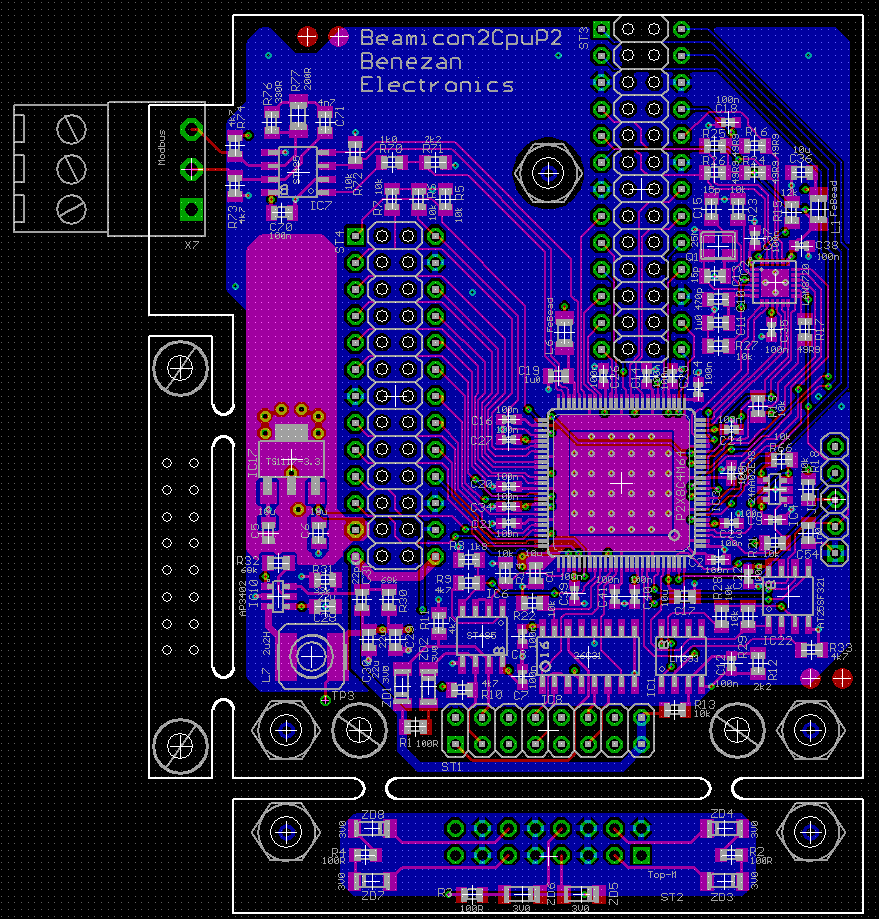
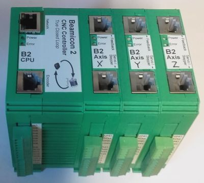
It is a piggyback board that will sit on top of the main board in the "B2CPU" module on the left side. The axis modules on the right side have a P1 each and are connected to the main module with a high speed serial bus.
The next step would be to implement some higher level protocol. I'm about to port the software for my CNC controller from the P1 to P2. But that won't be of much use for anybody else since the protocol is proprietary. Jesse (@avsa242) and Terry (@ke4pjw) have said that they have already made some experiments with TCP/IP or UDP.
If I remember correctly there was also a P1 project that had a TCP/IP implementation based on the ENC28J60. It was the "Thumper" internet radio by Harrison Pham. I think the Spin1 code could be ported to Spin2 without big problems but I don't know if it supports everything we need.
This is the latest driver with built in self test.
https://forums.parallax.com/discussion/118193/proptcp-beta-now-fully-mit-licensed-w-ajax-enabled-http-server-example/p1
I built lwip (Lightweight IP) for riscvp2. Only tried it with PPP over serial. I don't know how easy it would be to interface with a spin application. Connecting it to a spin serial driver wasn't bad. Getting it working with Ethernet isn't something I really want to spend my time on now. The version I used is probably really outdated by now. But if you're interested, you can find it at my github.
@ManAtWork , I've been writing an IP stack using your driver and accessory board. It's just barely usable for UDP, and it can do some other things such as replying to ARP requests and maintaining a local ARP cache, responding to ICMP pings, and sending TCP RST packets in response to attempts to talk to it via TCP. I'm planning on adding a DHCP client, a DNS resolver, mDNS, Zeroconf, and maybe IPv6 support.
I couldn't find a license specified in your driver - is it licensed under something like MIT? I'd like to post my work, together with a slightly modified version of your driver, on Github.
I'll start a new thread here once I upload my local repo to GitHub.
Wow, that is great news.") I have already been thinking about how to motivate somebody to write an IP stack or how to coordinate experiments from different contributors so that the result would hopefully be something useful for everybody but haven't got the time. I can hardly keep my head above the flood level of work and orders since I finished the driver. But you make great progress!
I have already been thinking about how to motivate somebody to write an IP stack or how to coordinate experiments from different contributors so that the result would hopefully be something useful for everybody but haven't got the time. I can hardly keep my head above the flood level of work and orders since I finished the driver. But you make great progress!
Yes of course, feel free to use the driver in anyway you like. You can just add the usual MIT license banner. Have you found any bugs?
I just want to summarize the discussion about full vs. half duplex in that thread (post #11 to #16). @Electrodude said he needs full duplex but wants to optimize the driver to use less cogs.
There had been suggestions (see page #1 and #2 of this thread) to use the streamer for transmitting which would possibly free some resources so that one cog could handle receiving and transmitting at the same time. The current driver uses one cog for each task and feeds/polls the shift registers directly in software. Using the steamer for TX would require pre-computing the CRC. Receiving needs constant attention and might require an interrupt triggered by RX_DV to be able to react quickly even while transmitting is in progress. I think it's going to be tough but should be possible.
Problem is, the preamble leads directly to the beginning of the data. No time in between... so it seems at first... Maybe if we put the streamer in "manual" mode (ie. Write the stream to register X)... one could analyze the preamble and switch the streamer over to HUBwrite mode....possibly meddling with the streamer timing (eggbeater?) to align the writes, at least to write whole bytes and not half-nibbles... after the streamer is fine, patch the beginning of the packet which was torn apart... or in the worst case re-arranging the whole packets afterwards.... if i had the hardware, i might try it... i guess it would be a only small modification to the PCB)..
We might stream the whole packet to LUTram and do the crc from there and copy it to HUBram exactly where it has to be. Think towards TCP/IP where you have a serial stream of data.. and a frame that is moving along with the read and write pointers (wrapped at framesize X) ... so to do that comfortably we might have to copy the frame anyways at least once.
I keep imagining ops like that too. But the streamer can only read from lutRAM, not write to it. Writes can only go to hubRAM.
Sorry for the confusion. In the early posts on page #1 of this thread I was also speculating about using the streamer for receiving. But it turned out that this would be really hard. It's much easier to use the streamer for transmitting because everything is predictable and the whole packet including CRC can be pre-calculated. Obviously you can't use it for both (full duplex) because there's only one streamer per cog and the FIFO can handle only one direction at a time.
LUT RAM could be used for buffering as long as no extra large packets are required (1522 byte limit).
I've not really been following this thread so this may have already been suggested but how about polled RX and streamed TX? You only initiate the TX at suitable times when you know for sure have a free cycle in the RX code and won't interfere with it, or otherwise when RX is idle. The TX CRC is precomputed prior to sending the packet out, by another client COG when it buffers it for TX. Actually it would have been really nice if the RMII COG could also do the TX CRC itself in advance using the P2's CRC instructions but this method could introduce too much instruction execution jitter due to egg-beater timing if RX work is also being done at the same time. It would likely only be doable in real RX idle time, reducing TX performance during full duplex operation. Having the client COG compute the CRC increases performance because the next outgoing CRC can be computed while transmitting and receiving other packets at the same time allowing proper full duplex operation.
For the sake of a good latency you might want to start the streamer on one COG simultaneously with the CRC of the same packet on another COG (the latter will finish before the packet is half-through)
doing CRC only in the idle time of the receiving COG will work but not while it is actually receiving (cause the FIFO is then occupied)
the latency for outgoing packets would increase dramatically with higher incoming traffic, quite hard to predict especially since network switches got relatively huge buffers nowadays that might keep our COG occupied with swathes of packets... it would be use case specific and also easy to DoS (denial of service attack)
having our In/Out duplex divided into two COGs seems appropiate, since we are on a concurrent, multi-processor system:)
I thought again, about the implications of doing RX/TX on one cog. The transfer from HUB to LUTram (for buffering) could take place in the inter-packet-gap but it would have to be quite fast.
What would be the fastest way to copy to LUTram ( how many clocks / WORD ?)
Fastest way to copy to LUT RAM from HUB is a block copy with SETQ2.
E.g.
this burst transfers at a rate of 1 P2 clock per 4 bytes read after the first read latency interval completes, although this can be affected by any parallel streamer bandwidth as well. For 100Mbps Ethernet the stolen bandwidth is only 3.125M transfers per second which is only a small component of the total hub bandwidth (at 200MHz it's less than 2% lost).
But transferring to LUT from HUB is not really of much use as you then have to read it out into COGRAM to do anything with it which takes 3 more clocks per long. Better to read directly into COGRAM (and put your executable code into LUTRAM for freeing up more space).
I was curious to see what sort of peak throughput this was capable of so extended the size of the example frame in @ManAtWork 's demo code to 1500 bytes (I just copied the I shut the P2 down and watched the laptop quickly start to cool off. I suspect this was more due to Wireshark with its ever-increasing log of packets flying by, but still pretty impressive speed
 ")
txDataarray to a new one withbyte $00[1486]after the Ethernet protocol) and sent it in a loop inTxDemo()- 6.4MBytes/sec as reported by my PC's network manager (200MHz Fsys). At 300MHz, 11.6MBytes/sec. I'd gone back to my desktop and forgotten I'd left the P2 running for awhile and noticed the sound of the fan on my laptop getting unusually loud. I switched back to it to find it was running at 82C and the fan over 3000RPMs.Cheers