OK, early termination (false carrier event) and inter-packet gap timer now also work. Next thing is the CRC calculation.
A strange thing I discovered is that on some occasions the LAN8720 hangs up and goes into some deadlock loop where CRS_DV is high almost all of the time. It's similar to what I encountered with the first (modified) board. It doesn't react to anything until I power-cycle it. Maybe some loose wire or I slipped off with the scope probe causing a short on some pin. It works reliable though when I don't touch it.
@ManAtWork said:
OK, early termination (false carrier event) and inter-packet gap timer now also work. Next thing is the CRC calculation.
There are two ways. You either CRC the whole packet except the CRC and then check if they are equal, or you CRC all data including the CRC itself and you should get out some magic value that indicates a valid packet.
Some algorithms also XOR the checksum at the very end with ##-1 and some use a complement polynom when your data word is reversed. when i did it, i had to experiment with different values i found on wikipedia to finally make it work.
Yes lots of experimentation is needed with CRCs to get them correct. Too many combinations of variables to choose wrong otherwise.
@rogloh said:
Yes lots of experimentation is needed with CRCs to get them correct. Too many combinations of variables to choose wrong otherwise.
Yes, so true. My head is aching. I thought I have understood everything and having Simonius' code as "cheat sheet" should make it easy. But I get different CRC results for different packets received.
polynomial reversed ($edb88320), check
data at smart pins comes in LSB first, check
SETQ value for CRCNIB is reversed (MSB used first), check
Maybe it has something to do with how the last bytes have to be treated if the packet length is not divisible by 4. I always shift in 32 bits so in this case I have a quarter/half/three quarters full shift register at the end of the packet. Maybe there is something wrong there. I think I'll use Wireshark to see what the PC actually sends out. So I can verify if I see the same length and content.
What I still do not understand: Why do I need to reverse the byte-order when writing to the packet buffer? (see MOVBYTS D,#%00_01_10_11 instruction) Of course, fields longer than one byte like the type field or MAC addresses need to be reversed because the Ethernet uses big-endian format where the P2 uses little-endian. But that should be the task of the higher level protocol. As low-level driver I handle all bytes strictly from lower to higher address. I don't even know what the data fields mean and where they start so I can't interpret them.
Smart pin P_SERIAL_RX and _TX modes shift to the right meaning the LSB is sent and received first. So if I read $44332211 from the smart pin RX shift register it means that the $11 arrived first and it should also be placed into the buffer at the lowest address. This is exactly what happens if I do a WRLONG or WFLONG. Or is there some point I'm missing?
Oh, I have totally forgotten that this was discussed earlier although I've discovered a post of my own in that thread. I hope we'll finish it successfully, this time.
rxDataLoop
waitse2 ' wait for real packet data
rdpin rxd0,pinRxd0
rdpin rxd1,pinRxd1 ' shift registers -> MSWs
rdpin dvBits,pinCrsDv
shr rxd0,#16
setword rxd1,rxd0,#0 ' combine rxd1:rxd0
mergew rxd1 ' shuffle bits
'movbyts rxd1,#%00_01_10_11 ' reverse bytewise NOT NECESSARY!
wflong rxd1 ' write to buffer
rev rxd1 ' crcnib needs MSB first
tjnf dvBits,#lastBytes ' CRS_DV not high all the time?
setq rxd1
rep #1,#8
crcnib rxCrc,rxPoly ' see comment below about rxPoly bit order
if_z djnz lenCnt,#rxDataLoop
jmp #rxAbort ' if we ever arrive here we have run out of buffer
' space (packet longer than 1522 bytes)
lastBytes ' end of packet, <4 bytes left
subr lenCnt,#maxBufLong-1
shl lenCnt,#2 ' byte length = longs*4
encod rxd0,dvBits
sub rxd0,#14
shr rxd0,#2 ' how many extra bytes? 0..3
add lenCnt,rxd0
shl rxd0,#1 wz ' how many nibbles? 0..6
if_nz setq rxd1 ' get back bit reversed data
if_nz rep #1,rxd0 ' if_nz avoids endless loop
if_nz crcnib rxCrc,rxPoly ' see comment below about rxPoly bit order
cmp rxCrc,finalCrc wz ' check for final value
if_nz jmp #rxAbort
add pktCnt,#1 ' success!
Interestingly, no byte re-ordering is necessary although there was a MOVBYTS instruction in the code from Simonius. I have cross checked this with Wireshark. I can see the exact same packet content as the PC sends. Example:
Another idea I had was to do packet filtering based on the destination MAC address as soon as it's received. This would probably save some CPU time and power but possibly not much.
Some 30 years ago when Ethernet was build from coax cable it was really some sort or "ether" where all participants listened to the same signal on the backbone. Therefore, everyone received all packets even those not meant for this destination. But nowadays every network is built in star configuration with network switches. The switch does the main job and pre-filters the packets by sending them only to the lines with the nodes of the correct destination address connected. So only the broadcasts and those packets where the exact destination is unknown are sent to all ports.
So I think we could leave it to the resposibilty of the higher level protocol to check if the destination address fits the local MAC. Any doubts or suggestions?
@ManAtWork said:
Another idea I had was to do packet filtering based on the destination MAC address as soon as it's received. This would probably save some CPU time and power but possibly not much.
Some 30 years ago when Ethernet was build from coax cable it was really some sort or "ether" where all participants listened to the same signal on the backbone. Therefore, everyone received all packets even those not meant for this destination. But nowadays every network is built in star configuration with network switches. The switch does the main job and pre-filters the packets by sending them only to the lines with the nodes of the correct destination address connected. So only the broadcasts and those packets where the exact destination is unknown are sent to all ports.
So I think we could leave it to the resposibilty of the higher level protocol to check if the destination address fits the local MAC. Any doubts or suggestions?
For applications where you will be a host you could be filtering on MAC DA being your own 48 bit value or the broadcast address (FF:FF:FF:FF:FF:FF) If you also want to process multicast and other MAC management frames you also need several others in the range 01:80:C2:xx:xx:xx but the interpretation of those start to get complicated and likely need to be controlled by another COG dealing with multicast group joins/leaves etc. Some type of MAC filtering table entries would be useful, but there is not a lot of time to look this up before the next byte arrives. So what is probably best is to process the RX packet by having a separate receive FIFO packet pointer structure (in addition to the packet data) that is only updated when a valid packet is received that you wanted, providing both the packet's start address in HUB and the packet's length (or the length can be combined with the data). The full packet data might be written into the HUB in the meantime as it arrives giving you the complete packet arrival time to decide whether it is needed via (multiple) table lookups etc. Then if the packet needs to be dropped for some reason (bad CRC, different MAC) , you just don't update the FIFO pointer or notify the client at the end of the packet, and you re-use the same HUB address for the next packet (effectively overwriting the prior packet you didn't want). There will need to be some client receive process that is keeping up too so you don't overflow the packet FIFO.
Another handy feature to include is a "promiscuous mode" setting where you can allow ALL packets in, disabling the MAC address filtering. Very useful for debug and packet sniffing etc. I'd also recommend including in the packet buffer's header the packet's arrival timestamp using the P2's timer. Again invaluable for debug.
You will need to consider buffering in general and probably create a wrapping FIFO block that will receive packets. Your PHY driver COG will need to manage this.
Actually one way to go is to have a single buffer structure that contains the packet length and timestamp at the start followed by the packet data (which all wrap in a fixed block of HUB RAM). If the packet length value is 0, it is still being received and if not zero it is the length of this packet and the packet is valid. You just need to update the length and timestamp longs at the end of the packet (in the IPG time), before moving onto the next packet. If the packet just received is bad/filtered out, you don't update the length but just rewind to the start of the previous packet before filling it again with data from the next packet.
@ManAtWork said:
So I think we could leave it to the resposibilty of the higher level protocol to check if the destination address fits the local MAC. Any doubts or suggestions?
In cases where you are attached to a HUB I think a MAC filtering mode is useful as we get a chance to drop it before we have to blast 100Mbps right into another COG. For normal applications our COG doesn't need/want to see the other host's LAN traffic and if we are not capable of operating with wirespeed processing rates, it will be wasteful to send the COG this extra unwanted traffic and reduces the performance it will be able to achieve.
This is why the promiscuous mode setting is so useful. You can then operate the PHY+MAC driver COGs either way, ie. all traffic to downstream processing COG(s), or only the desired incoming traffic. I'd recommend having the option to filter on MAC DA+broadcast, with the promiscuous mode config option.
Yes that is another option. Lots of ways to skin the cat. If you use pointers you can avoid some of the wraparound issues. Or you can detect if there will be enough space left in the FIFO buffer for another maximum sized packet.
I know this from the ENC28J60 which has an 8kB FIFO for received packets. But I think it's not needed. There are applications where you only need a request/answer pingpong game. One or maybe two buffers is enough in this case. And there are applications which transfer large files. In this case being able to process bursts of multiple packets would be useful. But as we don't have as much RAM as a PC and can't buffer the whole file the transfer will stall sooner or later if we can't keep up with the sender's data rate. So I'd think two buffers are still enough. I've already implemented a simple double buffering mechanism. If it turns out that we need more we can add that later.
If there is a dedicated COG for communication then two buffers would suffice. You have to deal with the data, buffered or not. 100 MBIT/s = 12.5 MB/s = 3.125 Million P2 words/ sec.... at ~ 100 MIP/s, it should be a piece of cake. if there are more than one datastreams, especially TCP, buffering gets interesting, quite complicated. UDP on the other hand, with most of the flow control happening in an application (be it in a PC or Propeller) could be done with a very lean memory footprint... buffering is mostly on the sender side... if a packet you sent doesn't get through, you might want to still have it and send it again until you receive the notice of reception from the other end
If there is a dedicated COG for communication then two buffers would suffice.
You mean another protocol COG, plus these two PHY COGs (tx+rx), that is purely handling the incoming packets arriving in the HUB RAM and does it's own packet buffering on top of this? If so then yes, two PHY buffers, one actively being written and the other the previously received packet being copied by the protocol COG, should suffice as long as this protocol COG can be servicing its queue every 6.72us and keep up with a temporary burst of small packets so it won't lose one arriving from the PHY. At say 200MHz we have 100MIPs to play with which is 672 instructions between 64 byte packets at the wire speed rate, and this is quite a lot of instructions to process it. The other way is to run a protocol stack in the application COG but this puts more of a burden on it keeping up, depending on what else it has to do, and you'd probably need to think about an interrupt scheme.
What software stack are you thinking about? Things like LWIP, uIP, Contiki spring to mind...
@rogloh said:
You mean another protocol COG, plus these two PHY COGs (tx+rx), that is purely handling the incoming packets arriving in the HUB RAM and does it's own packet buffering on top of this?
if you really want to store away your packets in the buffer, we might work out some scheme where there is space reserved in RAM for N packets (with each up to a maximum length of 1500 bytes) and the receiver will look for an empty slot and put the new packet in there and then each packet can be kept there as long as needed and afterwards the individual slots will be freed and reused....
incoming and outgoing packets can share the memory
for different sized packets it would be inefficient but it's simple
The other way is to run a protocol stack in the application COG but this puts more of a burden on it keeping up, depending on what else it has to do, and you'd probably need to think about an interrupt scheme.
yes, do it in realtime, trigger an interrupt each time a packet arrives and process it before the next one is possibly there and buffer overflow can never happen
buffering will only buy you a little time but it will not solve the problem that the 100 MBIT/s have to go somewhere (i.e. be processed)
What software stack are you thinking about? Things like LWIP, uIP, Contiki spring to mind...
Sooner or later someone wants to run a small webserver. So if you can compile/make one of the mentioned stacks, go ahead.
I might try and roll my own, but not TCP presumably and don't expect it to happen very soon
Yes of course. Buffering doesn't increase the sustained bandwidth if you can't keep up anyway, but it does allow bursts from multiple sources to arrive in clumps rather than needing to be neatly spaced out, which reduces the need for re-transmissions due to packet drops from any processing delays. A smallish buffer like 4-8k or so, can help these cases. The benefit is that a small fixed size buffer like this can hold multiple short packets which are the challenging ones to process fast given they have so little time between them.
I'm currently implementing the transceiver side. I thought this was much easier than the receiver because everything is pre-determined and you don't have to synchronize to external events. But it turns out that this also has some pitfalls. Calculating the CRC on the fly becomes tricky if the last longword is incomplete, I mean, if the length is not divisible by 4. The CRC has to be calculated from the remaining 0..3 bytes and immediately appended to the data stream which requires shifting if the length is odd. This would bust the CPU cycle limit between two consecutive TX buffer empty events for low clock frequencies. Tricks to avoid this by pre-fetching and lookahead-calculation of the CRC would make things even more complicated.
Because of that I've decided to handle the special cases at the beginning of the packet. Before activating TX_EN we have plenty of time to handle the 0..3 bytes and calculate the CRC for those. The CRC to be appended to the end is then always long aligned and no extra time is required.
The next step is to get it to work somehow. Then I'll check if it's possible to put the assembler code for transmitting into an inline Spin function so it can simply be called from the higher level protocol handler instead of requiring its own cog.
I've implemented a simple double buffering for received packets. It uses a packet counter and bit 0 of the counter decides in which buffer the packet is stored. No locks, pointers or linked lists are required and it can be easily extended to 4 or 8 buffers by using more bits.
Because of that I've decided to handle the special cases at the beginning of the packet. Before activating TX_EN we have plenty of time to handle the 0..3 bytes and calculate the CRC for those. The CRC to be appended to the end is then always long aligned and no extra time is required.
CRC's are not associative commutative to my knowledge, are you computing the entire CRC for these packets not divisible by 4 or something on the last 3 bytes?
The next step is to get it to work somehow. Then I'll check if it's possible to put the assembler code for transmitting into an inline Spin function so it can simply be called from the higher level protocol handler instead of requiring its own cog.
That could be handy but if you do this you would then need two protocol COGs, one for receive and one for transmit, plus another PHY receive COG. This is because while your TX COG is busy you can't receive more packets without another COG and if it's a long packet being sent, lots of short ones can arrive. Either way, 3 COGs might be needed no matter what, although with a combined TX+RX protocol COG that could just be your main application COG too.
I've implemented a simple double buffering for received packets. It uses a packet counter and bit 0 of the counter decides in which buffer the packet is stored. No locks, pointers or linked lists are required and it can be easily extended to 4 or 8 buffers by using more bits.
@rogloh said:
CRC's are not associative commutative to my knowledge, are you computing the entire CRC for these packets not divisible by 4 or something on the last 3 bytes?
Of course they aren't commutative, but they don't have to. I calculate the CRC for all the bytes in the right sequence. I just use a different grouping of the bytes (associative). For example, if the packet has a length of 63 bytes (without CRC) and starts with $00, $11, $22, $33... instead of starting with a longword of $33221100 I first pre-calculate the CRC for the first 3 bytes. Then I start to feed the smart pins with longwords but with shifted data:
preamble 1st longword: $55555500 (LSB comes first)
preamble 2nd long; $55555555
SFD and data: $221100D5
Then I continue to read longwords from the buffer starting at address buffer+3 which contains the $33 byte. This way the data ends on a longword boundary (with odd address, though) and I can append the CRC seamlessly.
That could be handy but if you do this you would then need two protocol COGs, one for receive and one for transmit, plus another PHY receive COG. This is because while your TX COG is busy you can't receive more packets without another COG and if it's a long packet being sent, lots of short ones can arrive. Either way, 3 COGs might be needed no matter what...
I think that is unlikely to happen. Short packets are usually commands and long packets only occur when large chunks of data needs to be transferred. A client usually doesn't send lots of new commands to the server before the older ones are completely executed. Or if a stream of data is transferred with variable data rate then a short packet indicates that the buffer has run low and the sender is waiting for new data to arrive. As I said at the beginning of the discussion, network trafic tends to be highly asymetric. You either have more upload or more download.
But there's no need to speculate about that, now. We can simply try out and tune the parameters like number of buffers as soon as everything is available. But we agree that cogs are more precious than a few kB of memory.
Ok, maybe my view is a bit limited. My target applications are quite simple like a data logger or some type of printer (which a CNC machine is also from the data flow point of view). There, you usually only can process one job at a time, anyway. If there are requests from multiple clients pending you need to tell the other ones to wait until the current job is done.
Of course, if you plan to use the P2 as web or file server there can be multiple ports open at the same time. Then the scenario you described is realistic and multiple short packets can arrive while long packets are still being processed. But then it shouldn't be a problem to assign 3 cogs or even more to that task.
Anyway, I think it's good to make the low level driver a simple as possible and use as little resources as possible so that the minimum configuration is not bloated. The decision to add more cogs and more bufffers should be left to the higher level protocol handler.
For the same reason I won't implement packet filtering. If done in the receiver cog it could only look for a single MAC address or broadcasts. Multicasts require a dynamic table and more time to process. And terminating the packet reception early won't gain anything as the receiving cog had to wait for the next packet, anyway.
@rogloh said:
CRC's are not associative commutative to my knowledge, are you computing the entire CRC for these packets not divisible by 4 or something on the last 3 bytes?
Of course they aren't commutative, but they don't have to. I calculate the CRC for all the bytes in the right sequence. I just use a different grouping of the bytes (associative). For example, if the packet has a length of 63 bytes (without CRC) and starts with $00, $11, $22, $33... instead of starting with a longword of $33221100 I first pre-calculate the CRC for the first 3 bytes. Then I start to feed the smart pins with longwords but with shifted data:
preamble 1st longword: $55555500 (LSB comes first)
preamble 2nd long; $55555555
SFD and data: $221100D5
Then I continue to read longwords from the buffer starting at address buffer+3 which contains the $33 byte. This way the data ends on a longword boundary (with odd address, though) and I can append the CRC seamlessly.
OK got it. I didn't realize you did the 1-3 extra bytes at the start when not long word aligned, and brought it back into alignment so it ended on a long. I thought you were doing things another way and merging two CRCs in different orders.
@ManAtWork said:
Ok, maybe my view is a bit limited. My target applications are quite simple like a data logger or some type of printer (which a CNC machine is also from the data flow point of view). There, you usually only can process one job at a time, anyway. If there are requests from multiple clients pending you need to tell the other ones to wait until the current job is done.
Of course, if you plan to use the P2 as web or file server there can be multiple ports open at the same time. Then the scenario you described is realistic and multiple short packets can arrive while long packets are still being processed. But then it shouldn't be a problem to assign 3 cogs or even more to that task.
Right, it's useful to think about different applications of the same PHY driver rather than a single use case, if the software is to be eventually used by other P2 users.
For the same reason I won't implement packet filtering. If done in the receiver cog it could only look for a single MAC address or broadcasts. Multicasts require a dynamic table and more time to process. And terminating the packet reception early won't gain anything as the receiving cog had to wait for the next packet, anyway.
If we find we need to filter at some point to reduce incoming load from hub LAN segments, detecting our MAC DA, the broadcasts and (all) public multicast addressed packets can be filtered with two very simple tests on the first 48 bits of the packet. Eg.
Exact 48 bit match for unicast DA.
Match a 1 bit in the LSB of the first MAC octet for all multicasts and this includes the broadcast MAC FF:FF:FF:FF:FF:FF.
I suspect this could be done in the PHY RX driver even if it had to be done at the end in IPG time by reading back data from HUB RAM.
In some higher level protocol/application COG that is dealing with these packets, further filtering could be done to classify the packet into unicast, broadcasts and any subscribed multicast groups. If you can terminate early and you include a larger input buffer (not just ping/pong) it helps reduce load on the next COG that examines the incoming packets in the queue and now gives it more free time to process more packets from the buffer in cases where you are on a shared LAN and see traffic from other hosts you don't want to process. This way if the underlying system performance is (say) only 25Mbps or so of packet servicing due to other bottlenecks in the COG like waiting on external memory transfers, or doing more complex lookups, deeper packet inspection, IP checksum stuff, or writing to disk etc, you don't have to worry about all the other unwanted traffic on the LAN arriving and overloading it even more. It can be helpful in the cases where you are not always able to process everything arriving at wire speed all the time, and this is quite common, it is why TCP rate adapts as soon as any packets are lost. It is adapting to the slowest speed (link speed or processing rate) in the path. Of course if you are going to be attached to a switch not a hub, you are only going to see the packets actually destined for the P2 host arriving there (including all broadcasts), so I agree the filtering is less of an issue in that situation.
Another possible pitfall that just came to my mind: asynchronous clocks and metastability. We use three smart pins for receiving and transmitting each, two data pins plus TX_EN or CRS_DV. They all use the same clock input. However, because the REFCLK from the PHY is asynchronous it might happen that one of the smart pins starts one P2 sysclock earlier or later than the others. When receving this should not cause problems as long as the sysclock is fast enough so that the sample point is within the valid setup/hold window. It takes at least one instruction or two clocks from the buffer-full event to the RDPIN instruction so the other smart pin should be ready at that time, too.
For transmitting however, this is a bit more complicated. One of the smart pins might start immediately at a rising edge of the REFCLK and the others one 50MHz period later. This would ruin the data being sent. So we either need to carefully synchronize the startup of the smart pins to the REFCLK or put a single flipflop into the common path of the B inputs of all three smart pins to make sure they all see the same synchronized REFCLK.
Looking at the smart pin diagram...
The block "Comperator & Logic & Schmitt (%MMM)" is on the left side and the -3..+3 multiplexer "Logic input (%A_B_F)" is on the right side. So applying P_SCHMITT_A + P_SYNC_IO to the WRPIN value of the clock input should activate Schmitt trigger and a Flipflop for ALL the three smart pins, I assume. This is hard to verify by trial and error...
@ManAtWork said:
The block "Comperator & Logic & Schmitt (%MMM)" is on the left side and the -3..+3 multiplexer "Logic input (%A_B_F)" is on the right side. So applying P_SCHMITT_A + P_SYNC_IO to the WRPIN value of the clock input should activate Schmitt trigger and a Flipflop for ALL the three smart pins, I assume. This is hard to verify by trial and error...
That's exactly correct. All those low-level functions are in the pad-ring blocks. There is schematic of it if you want to look.
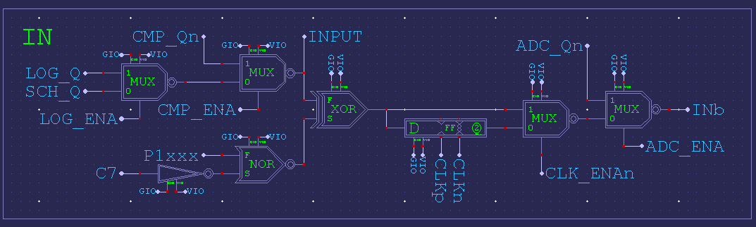
EDIT: Here's the MUX block. Somewhat more to it than the block diagram indicates. It contains inversion as well as the flip-flop and all the input sources of that pin.
Ok, then I'll put the flipflop in at the clock input. We then also need flipflops in the RX data path so that we don't create an additional hold time requirement. And I have to check if the setup time for the TX data pins to the next rising clock edge is still inside the spec.
Probably good to register all pins. TX isn't responding to the REFCLK is it? Oh, it is clocked from REFCLK, maybe don't register TX then. EDIT: Ah, that's right, the clock never stops. It depends on TX_EN timing instead. Okay, no problem registering all pins.
That's kind of cool. It hides all the issues SPI normally has with getting the number of clock pulses aligned with data.
Help, the RMII spec doc is lacking somewhat in the timing details.
TX_EN indicates that the MAC is presenting di-bits on TXD[1:0] for transmission. TX_EN shall be asserted synchronously with the first nibble of the preamble and shall remain asserted while all di-bits to be transmitted are presented. TX_EN shall be negated prior to the first REF_CLK rising edge following the final di-bit of a frame. TX_EN shall transition synchronously with respect to REF_CLK.
And then the diagram below that shows the TX_EN rising with a rising REFCLK in the middle of the first di-bits. Well, I think that's the first di-bits because they're the first %01. The diagram isn't clear on the start of preamble either as it has the preamble box border on the %00 prior.
Normal way is to transition all outputs on same edge. Which means I'd want to move TX_EN rise to either half a REFCLK earlier to the start of preamble or half a REFCLK later to the transition from first di-bits to second di-bits.
EDIT: Ah, I think the next blurb is the answer:
TXD[1:0] shall transition synchronously with respect to REF_CLK. When TX_EN is asserted, TXD[1:0] are accepted for transmission by the PHY.
Two good points are made: One, it clearly says all outputs transition together (synchronously). Two, TX_EN has to be high for even the preamble to be transmitted. So, it goes high along with outputting first di-bits of preamble.
And if the diagram has anything correct then that is saying outputs transition on falling REFCLK.


Comments
              mov     tmp,#%001<<6
              or      tmp,pinCrsDv
              setse1  tmp                       ' CRS rising edge
...
              pollse1
waitIpg       setq    timeMinIpg
              waitse1 wc                        ' wait min inter-packet gap, C=timeout
        if_nc jmp     #waitIpg                  ' repeat if CRS=1 detected (not idle)
              jmp     #rxMainLoop
That doesn't work, of course. Reading the manual carefully sometimes helps.") Should be...
Should be...
waitIpg getct tmp add tmp,timeMinIpg setq tmp waitse1 wc ' wait min inter-packet gap, C=timeout if_nc jmp #waitIpg ' repeat if CRS=1 detected (not idle)OK, early termination (false carrier event) and inter-packet gap timer now also work. Next thing is the CRC calculation.
A strange thing I discovered is that on some occasions the LAN8720 hangs up and goes into some deadlock loop where CRS_DV is high almost all of the time. It's similar to what I encountered with the first (modified) board. It doesn't react to anything until I power-cycle it. Maybe some loose wire or I slipped off with the scope probe causing a short on some pin. It works reliable though when I don't touch it.
There are two ways. You either CRC the whole packet except the CRC and then check if they are equal, or you CRC all data including the CRC itself and you should get out some magic value that indicates a valid packet.
Some algorithms also XOR the checksum at the very end with ##-1 and some use a complement polynom when your data word is reversed. when i did it, i had to experiment with different values i found on wikipedia to finally make it work.
Yes lots of experimentation is needed with CRCs to get them correct. Too many combinations of variables to choose wrong otherwise.
Some earlier work we did on this was posted here https://forums.parallax.com/discussion/comment/1521854/#Comment_1521854
Yes, so true. My head is aching. I thought I have understood everything and having Simonius' code as "cheat sheet" should make it easy. But I get different CRC results for different packets received.
Maybe it has something to do with how the last bytes have to be treated if the packet length is not divisible by 4. I always shift in 32 bits so in this case I have a quarter/half/three quarters full shift register at the end of the packet. Maybe there is something wrong there. I think I'll use Wireshark to see what the PC actually sends out. So I can verify if I see the same length and content.
What I still do not understand: Why do I need to reverse the byte-order when writing to the packet buffer? (see MOVBYTS D,#%00_01_10_11 instruction) Of course, fields longer than one byte like the type field or MAC addresses need to be reversed because the Ethernet uses big-endian format where the P2 uses little-endian. But that should be the task of the higher level protocol. As low-level driver I handle all bytes strictly from lower to higher address. I don't even know what the data fields mean and where they start so I can't interpret them.
Smart pin P_SERIAL_RX and _TX modes shift to the right meaning the LSB is sent and received first. So if I read $44332211 from the smart pin RX shift register it means that the $11 arrived first and it should also be placed into the buffer at the lowest address. This is exactly what happens if I do a WRLONG or WFLONG. Or is there some point I'm missing?
I can't say I've seen where Ethernet has any Endianess other than least-bit-first. I wouldn't be doing any byte swapping.
Oh, I have totally forgotten that this was discussed earlier although I've discovered a post of my own in that thread.") I hope we'll finish it successfully, this time.
I hope we'll finish it successfully, this time.
This is my code:
rxDataLoop
              waitse2                           ' wait for real packet data
              rdpin   rxd0,pinRxd0
              rdpin   rxd1,pinRxd1              ' shift registers -> MSWs
              rdpin   dvBits,pinCrsDv
              shr     rxd0,#16
              setword rxd1,rxd0,#0              ' combine rxd1:rxd0
              mergew  rxd1                      ' shuffle bits
              'movbyts rxd1,#%00_01_10_11        ' reverse bytewise NOT NECESSARY!
              wflong  rxd1                      ' write to buffer
              rev     rxd1                      ' crcnib needs MSB first
              tjnf    dvBits,#lastBytes         ' CRS_DV not high all the time?
              setq    rxd1
              rep     #1,#8
              crcnib  rxCrc,rxPoly              ' see comment below about rxPoly bit order
        if_z  djnz    lenCnt,#rxDataLoop
              jmp     #rxAbort                  ' if we ever arrive here we have run out of buffer
                                                ' space (packet longer than 1522 bytes)

lastBytes                                       ' end of packet, <4 bytes left
              subr    lenCnt,#maxBufLong-1
              shl     lenCnt,#2                 ' byte length = longs*4
              encod   rxd0,dvBits
              sub     rxd0,#14
              shr     rxd0,#2                   ' how many extra bytes? 0..3
              add     lenCnt,rxd0
              shl     rxd0,#1 wz                ' how many nibbles? 0..6
        if_nz setq    rxd1                      ' get back bit reversed data
        if_nz rep     #1,rxd0                   ' if_nz avoids endless loop
        if_nz crcnib  rxCrc,rxPoly              ' see comment below about rxPoly bit order
              cmp     rxCrc,finalCrc wz         ' check for final value
        if_nz jmp     #rxAbort
              add     pktCnt,#1                 ' success!
Interestingly, no byte re-ordering is necessary although there was a MOVBYTS instruction in the code from Simonius. I have cross checked this with Wireshark. I can see the exact same packet content as the PC sends. Example:
Another idea I had was to do packet filtering based on the destination MAC address as soon as it's received. This would probably save some CPU time and power but possibly not much.
Some 30 years ago when Ethernet was build from coax cable it was really some sort or "ether" where all participants listened to the same signal on the backbone. Therefore, everyone received all packets even those not meant for this destination. But nowadays every network is built in star configuration with network switches. The switch does the main job and pre-filters the packets by sending them only to the lines with the nodes of the correct destination address connected. So only the broadcasts and those packets where the exact destination is unknown are sent to all ports.
So I think we could leave it to the resposibilty of the higher level protocol to check if the destination address fits the local MAC. Any doubts or suggestions?
For applications where you will be a host you could be filtering on MAC DA being your own 48 bit value or the broadcast address (FF:FF:FF:FF:FF:FF) If you also want to process multicast and other MAC management frames you also need several others in the range 01:80:C2:xx:xx:xx but the interpretation of those start to get complicated and likely need to be controlled by another COG dealing with multicast group joins/leaves etc. Some type of MAC filtering table entries would be useful, but there is not a lot of time to look this up before the next byte arrives. So what is probably best is to process the RX packet by having a separate receive FIFO packet pointer structure (in addition to the packet data) that is only updated when a valid packet is received that you wanted, providing both the packet's start address in HUB and the packet's length (or the length can be combined with the data). The full packet data might be written into the HUB in the meantime as it arrives giving you the complete packet arrival time to decide whether it is needed via (multiple) table lookups etc. Then if the packet needs to be dropped for some reason (bad CRC, different MAC) , you just don't update the FIFO pointer or notify the client at the end of the packet, and you re-use the same HUB address for the next packet (effectively overwriting the prior packet you didn't want). There will need to be some client receive process that is keeping up too so you don't overflow the packet FIFO.
Another handy feature to include is a "promiscuous mode" setting where you can allow ALL packets in, disabling the MAC address filtering. Very useful for debug and packet sniffing etc. I'd also recommend including in the packet buffer's header the packet's arrival timestamp using the P2's timer. Again invaluable for debug.
You will need to consider buffering in general and probably create a wrapping FIFO block that will receive packets. Your PHY driver COG will need to manage this.
Actually one way to go is to have a single buffer structure that contains the packet length and timestamp at the start followed by the packet data (which all wrap in a fixed block of HUB RAM). If the packet length value is 0, it is still being received and if not zero it is the length of this packet and the packet is valid. You just need to update the length and timestamp longs at the end of the packet (in the IPG time), before moving onto the next packet. If the packet just received is bad/filtered out, you don't update the length but just rewind to the start of the previous packet before filling it again with data from the next packet.
In cases where you are attached to a HUB I think a MAC filtering mode is useful as we get a chance to drop it before we have to blast 100Mbps right into another COG. For normal applications our COG doesn't need/want to see the other host's LAN traffic and if we are not capable of operating with wirespeed processing rates, it will be wasteful to send the COG this extra unwanted traffic and reduces the performance it will be able to achieve.
This is why the promiscuous mode setting is so useful. You can then operate the PHY+MAC driver COGs either way, ie. all traffic to downstream processing COG(s), or only the desired incoming traffic. I'd recommend having the option to filter on MAC DA+broadcast, with the promiscuous mode config option.
you could use a simple linked list to keep the packets lined up
Yes that is another option. Lots of ways to skin the cat. If you use pointers you can avoid some of the wraparound issues. Or you can detect if there will be enough space left in the FIFO buffer for another maximum sized packet.
I know this from the ENC28J60 which has an 8kB FIFO for received packets. But I think it's not needed. There are applications where you only need a request/answer pingpong game. One or maybe two buffers is enough in this case. And there are applications which transfer large files. In this case being able to process bursts of multiple packets would be useful. But as we don't have as much RAM as a PC and can't buffer the whole file the transfer will stall sooner or later if we can't keep up with the sender's data rate. So I'd think two buffers are still enough. I've already implemented a simple double buffering mechanism. If it turns out that we need more we can add that later.
Definitely. Two is a very small buffer.
If there is a dedicated COG for communication then two buffers would suffice. You have to deal with the data, buffered or not. 100 MBIT/s = 12.5 MB/s = 3.125 Million P2 words/ sec.... at ~ 100 MIP/s, it should be a piece of cake. if there are more than one datastreams, especially TCP, buffering gets interesting, quite complicated. UDP on the other hand, with most of the flow control happening in an application (be it in a PC or Propeller) could be done with a very lean memory footprint... buffering is mostly on the sender side... if a packet you sent doesn't get through, you might want to still have it and send it again until you receive the notice of reception from the other end
You mean another protocol COG, plus these two PHY COGs (tx+rx), that is purely handling the incoming packets arriving in the HUB RAM and does it's own packet buffering on top of this? If so then yes, two PHY buffers, one actively being written and the other the previously received packet being copied by the protocol COG, should suffice as long as this protocol COG can be servicing its queue every 6.72us and keep up with a temporary burst of small packets so it won't lose one arriving from the PHY. At say 200MHz we have 100MIPs to play with which is 672 instructions between 64 byte packets at the wire speed rate, and this is quite a lot of instructions to process it. The other way is to run a protocol stack in the application COG but this puts more of a burden on it keeping up, depending on what else it has to do, and you'd probably need to think about an interrupt scheme.
What software stack are you thinking about? Things like LWIP, uIP, Contiki spring to mind...
if you really want to store away your packets in the buffer, we might work out some scheme where there is space reserved in RAM for N packets (with each up to a maximum length of 1500 bytes) and the receiver will look for an empty slot and put the new packet in there and then each packet can be kept there as long as needed and afterwards the individual slots will be freed and reused....
incoming and outgoing packets can share the memory
for different sized packets it would be inefficient but it's simple
yes, do it in realtime, trigger an interrupt each time a packet arrives and process it before the next one is possibly there and buffer overflow can never happen
buffering will only buy you a little time but it will not solve the problem that the 100 MBIT/s have to go somewhere (i.e. be processed)
Sooner or later someone wants to run a small webserver. So if you can compile/make one of the mentioned stacks, go ahead.
I might try and roll my own, but not TCP presumably and don't expect it to happen very soon
Yes of course. Buffering doesn't increase the sustained bandwidth if you can't keep up anyway, but it does allow bursts from multiple sources to arrive in clumps rather than needing to be neatly spaced out, which reduces the need for re-transmissions due to packet drops from any processing delays. A smallish buffer like 4-8k or so, can help these cases. The benefit is that a small fixed size buffer like this can hold multiple short packets which are the challenging ones to process fast given they have so little time between them.
I'm currently implementing the transceiver side. I thought this was much easier than the receiver because everything is pre-determined and you don't have to synchronize to external events. But it turns out that this also has some pitfalls. Calculating the CRC on the fly becomes tricky if the last longword is incomplete, I mean, if the length is not divisible by 4. The CRC has to be calculated from the remaining 0..3 bytes and immediately appended to the data stream which requires shifting if the length is odd. This would bust the CPU cycle limit between two consecutive TX buffer empty events for low clock frequencies. Tricks to avoid this by pre-fetching and lookahead-calculation of the CRC would make things even more complicated.
Because of that I've decided to handle the special cases at the beginning of the packet. Before activating TX_EN we have plenty of time to handle the 0..3 bytes and calculate the CRC for those. The CRC to be appended to the end is then always long aligned and no extra time is required.
The next step is to get it to work somehow. Then I'll check if it's possible to put the assembler code for transmitting into an inline Spin function so it can simply be called from the higher level protocol handler instead of requiring its own cog.
I've implemented a simple double buffering for received packets. It uses a packet counter and bit 0 of the counter decides in which buffer the packet is stored. No locks, pointers or linked lists are required and it can be easily extended to 4 or 8 buffers by using more bits.
CRC's are not associative commutative to my knowledge, are you computing the entire CRC for these packets not divisible by 4 or something on the last 3 bytes?
That could be handy but if you do this you would then need two protocol COGs, one for receive and one for transmit, plus another PHY receive COG. This is because while your TX COG is busy you can't receive more packets without another COG and if it's a long packet being sent, lots of short ones can arrive. Either way, 3 COGs might be needed no matter what, although with a combined TX+RX protocol COG that could just be your main application COG too.
Handy that you can extend it.
Of course they aren't commutative, but they don't have to. I calculate the CRC for all the bytes in the right sequence. I just use a different grouping of the bytes (associative). For example, if the packet has a length of 63 bytes (without CRC) and starts with $00, $11, $22, $33... instead of starting with a longword of $33221100 I first pre-calculate the CRC for the first 3 bytes. Then I start to feed the smart pins with longwords but with shifted data:
Then I continue to read longwords from the buffer starting at address buffer+3 which contains the $33 byte. This way the data ends on a longword boundary (with odd address, though) and I can append the CRC seamlessly.
I think that is unlikely to happen. Short packets are usually commands and long packets only occur when large chunks of data needs to be transferred. A client usually doesn't send lots of new commands to the server before the older ones are completely executed. Or if a stream of data is transferred with variable data rate then a short packet indicates that the buffer has run low and the sender is waiting for new data to arrive. As I said at the beginning of the discussion, network trafic tends to be highly asymetric. You either have more upload or more download.
But there's no need to speculate about that, now. We can simply try out and tune the parameters like number of buffers as soon as everything is available. But we agree that cogs are more precious than a few kB of memory.
Ok, maybe my view is a bit limited. My target applications are quite simple like a data logger or some type of printer (which a CNC machine is also from the data flow point of view). There, you usually only can process one job at a time, anyway. If there are requests from multiple clients pending you need to tell the other ones to wait until the current job is done.
Of course, if you plan to use the P2 as web or file server there can be multiple ports open at the same time. Then the scenario you described is realistic and multiple short packets can arrive while long packets are still being processed. But then it shouldn't be a problem to assign 3 cogs or even more to that task.
Anyway, I think it's good to make the low level driver a simple as possible and use as little resources as possible so that the minimum configuration is not bloated. The decision to add more cogs and more bufffers should be left to the higher level protocol handler.
For the same reason I won't implement packet filtering. If done in the receiver cog it could only look for a single MAC address or broadcasts. Multicasts require a dynamic table and more time to process. And terminating the packet reception early won't gain anything as the receiving cog had to wait for the next packet, anyway.
OK got it. I didn't realize you did the 1-3 extra bytes at the start when not long word aligned, and brought it back into alignment so it ended on a long. I thought you were doing things another way and merging two CRCs in different orders.
Right, it's useful to think about different applications of the same PHY driver rather than a single use case, if the software is to be eventually used by other P2 users.
If we find we need to filter at some point to reduce incoming load from hub LAN segments, detecting our MAC DA, the broadcasts and (all) public multicast addressed packets can be filtered with two very simple tests on the first 48 bits of the packet. Eg.
I suspect this could be done in the PHY RX driver even if it had to be done at the end in IPG time by reading back data from HUB RAM.
In some higher level protocol/application COG that is dealing with these packets, further filtering could be done to classify the packet into unicast, broadcasts and any subscribed multicast groups. If you can terminate early and you include a larger input buffer (not just ping/pong) it helps reduce load on the next COG that examines the incoming packets in the queue and now gives it more free time to process more packets from the buffer in cases where you are on a shared LAN and see traffic from other hosts you don't want to process. This way if the underlying system performance is (say) only 25Mbps or so of packet servicing due to other bottlenecks in the COG like waiting on external memory transfers, or doing more complex lookups, deeper packet inspection, IP checksum stuff, or writing to disk etc, you don't have to worry about all the other unwanted traffic on the LAN arriving and overloading it even more. It can be helpful in the cases where you are not always able to process everything arriving at wire speed all the time, and this is quite common, it is why TCP rate adapts as soon as any packets are lost. It is adapting to the slowest speed (link speed or processing rate) in the path. Of course if you are going to be attached to a switch not a hub, you are only going to see the packets actually destined for the P2 host arriving there (including all broadcasts), so I agree the filtering is less of an issue in that situation.
Another possible pitfall that just came to my mind: asynchronous clocks and metastability. We use three smart pins for receiving and transmitting each, two data pins plus TX_EN or CRS_DV. They all use the same clock input. However, because the REFCLK from the PHY is asynchronous it might happen that one of the smart pins starts one P2 sysclock earlier or later than the others. When receving this should not cause problems as long as the sysclock is fast enough so that the sample point is within the valid setup/hold window. It takes at least one instruction or two clocks from the buffer-full event to the RDPIN instruction so the other smart pin should be ready at that time, too.
For transmitting however, this is a bit more complicated. One of the smart pins might start immediately at a rising edge of the REFCLK and the others one 50MHz period later. This would ruin the data being sent. So we either need to carefully synchronize the startup of the smart pins to the REFCLK or put a single flipflop into the common path of the B inputs of all three smart pins to make sure they all see the same synchronized REFCLK.
Looking at the smart pin diagram...
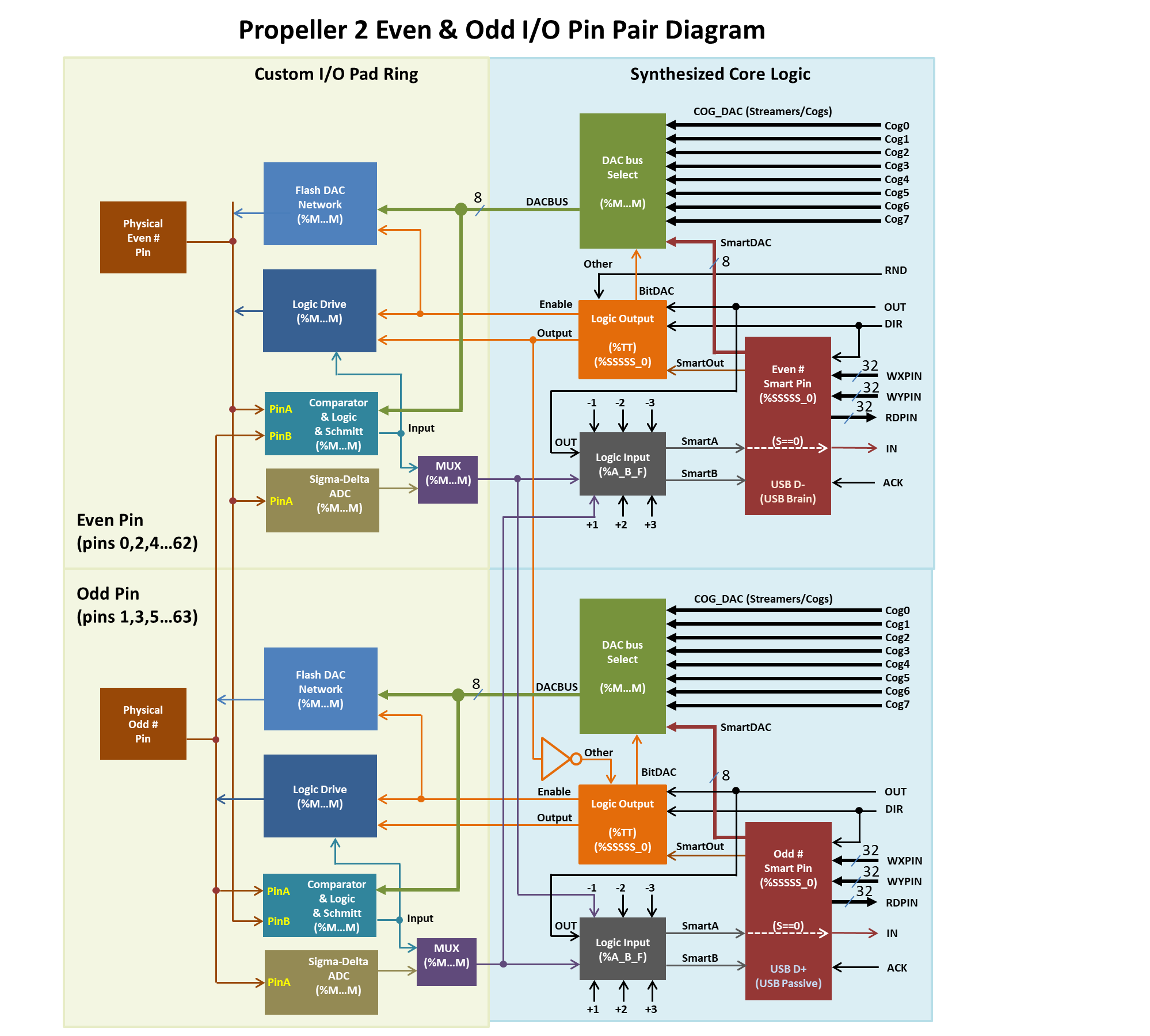
The block "Comperator & Logic & Schmitt (%MMM)" is on the left side and the -3..+3 multiplexer "Logic input (%A_B_F)" is on the right side. So applying P_SCHMITT_A + P_SYNC_IO to the WRPIN value of the clock input should activate Schmitt trigger and a Flipflop for ALL the three smart pins, I assume. This is hard to verify by trial and error...
That's exactly correct. All those low-level functions are in the pad-ring blocks. There is schematic of it if you want to look.
EDIT: Here's the MUX block. Somewhat more to it than the block diagram indicates. It contains inversion as well as the flip-flop and all the input sources of that pin.
Ok, then I'll put the flipflop in at the clock input. We then also need flipflops in the RX data path so that we don't create an additional hold time requirement. And I have to check if the setup time for the TX data pins to the next rising clock edge is still inside the spec.
Probably good to register all pins. TX isn't responding to the REFCLK is it? Oh, it is clocked from REFCLK, maybe don't register TX then. EDIT: Ah, that's right, the clock never stops. It depends on TX_EN timing instead. Okay, no problem registering all pins.
That's kind of cool. It hides all the issues SPI normally has with getting the number of clock pulses aligned with data.
Help, the RMII spec doc is lacking somewhat in the timing details.
And then the diagram below that shows the TX_EN rising with a rising REFCLK in the middle of the first di-bits. Well, I think that's the first di-bits because they're the first %01. The diagram isn't clear on the start of preamble either as it has the preamble box border on the %00 prior.
Normal way is to transition all outputs on same edge. Which means I'd want to move TX_EN rise to either half a REFCLK earlier to the start of preamble or half a REFCLK later to the transition from first di-bits to second di-bits.
EDIT: Ah, I think the next blurb is the answer:
Two good points are made: One, it clearly says all outputs transition together (synchronously). Two, TX_EN has to be high for even the preamble to be transmitted. So, it goes high along with outputting first di-bits of preamble.
And if the diagram has anything correct then that is saying outputs transition on falling REFCLK.