

RMII Ethernet interface, driver software
 ManAtWork
Posts: 2,367
ManAtWork
Posts: 2,367
The new hardware and assembly language manuals look very good. But unfortunatelly, they still lack some important information about the streamer and bit manipulation commands I'll probably need for this so I have to ask here...
I'm currently evaluating if it would be possible to directly feed an ethernet PHY chip with RMII interface with the P2. For my CNC controller project I don't need a TCP/IP stack but access to raw ethernet packets. It would be possible to use a Wiznet W5500 or W6100 chip but, first, I don't want to be dependant on a particular supplier and, second, it's totally overkill in terms of money, board space and register/driver complexity. And third, bit banging the protocol may enable the implementation of EtherCAT, one day...
The RMII interface mainly uses a clock of 50MHz and two data lines to transfer a 100Mb/s data stream. Well, actally it's four data lines for full duplex RX/TX. The PHY chips have an "elastic" FIFO buffer to compensate frequency drifts from transmitter to receiver so that the data is always phase locked to the same local 50 MHz reference clock. This refernece clock could also be used as input to the PLL for the system clock of the P2 so we can use a fixed NCO divider and don't have to care about phase drift.
I think it should be possible to use either two cogs with streamers, one for transmitting and one for receiving, or one cog and four smart pins in synchronous serial mode. The two bits per clock could be split and merged with the SPLITW and MERGEW assembly commands. Or we could use a mix of the two methods, for example, using the streamer for transmitting and two smart pins for receiving.
Reading two 32 bit longs from the smart pins every 640ns should be possible with interrupts. One cog can execute 64 instructions during this time. Not much but enough to store the data and do the CRC calculation.
Comments
So first question: How can I use the streamer to read data from the hub RAM so that each even bit goes to one pin and each odd bit to another? Is mode 1001 with the "e" bit=1 and the channel selection "babababa" the right one? The "ppppp" bits select the pin group and the "a" bit selects top/bottom first, correct?
Second question: Is there a reason why there are so many PHY chips? What are the differences? Are there any objections against the LAN8720A? Because I have lots of them in stock which might be useful in the current semiconductor crisis...
It is absolutely possible. I know because i have a setup running. If only i had the time/motivation to finish it. i would open-source it.
They key is, you sample bit 0 / 1 and RXDV_CRS at the same time ( using the sync_rx smartpin mode) and then sync that to the ethernet preamble (trigger on the first '1' that appears)
then do the reordering and merging
then do the CRC
then save it to the FIFO
with one core for reception and a half core for sending you can have a 100MBIT/s full duplex, low latency connection
you need ARP and IP/UDP in most cases and that could be crammed into the second core i guess.
you will have to buffer a number of bytes to get a reliable dataflow so i am not sure if ethercat would allow for the delay ( in the order of 1.0 msμs)
Yes, full duplex with only one cog would be hard, not because of speed limits but because of the hub RAM interface. Interleaved reads and writes would disable the use of the streamer because the RDFAST FIFO would be disturbed by WRLONGs and vice versa.
While for receiving you have to be ready to accept a packet at any time, for transmitting a short delay of several microseconds wouldn't hurt. So we could copy the TX data to LUT RAM and bit bang it locally to smart pins while using the streamer for RX. Commands to the cog can only be read from a hub RAM mail box in the idle time between packets. Or we could use a smart pin in repository mode for that. I have to figure out what's the best way...
Maybe we'll need two cogs, anyway. As already said, the receiving cog needs to be ready all the time. But the transmitting cog can process the higher level protocol between sending packets.
EtherCAT is a completely different protocol. A packet is shifted through all nodes while each node picks and modifies its data field on the fly, i.e. while the packet is being transmitted. So each node in the chain sees a different packet. The buffer for the packet needs to be in cog or LUT ram and only a latency in the order of 1µs is allowed. But you only need very little bandwidth to hub RAM because only a small portion of the packet is of interest.
I wonder if full duplex provides much benefit at all. In most cases one of the data directions is dominant. In sensor applications, scopes, logic analyzers and data loggers you have more upstream bandwidth than downstream. In mainly actor applications like CNC machines, printers, displays etc. you have more downstream traffic. The cases where you need both simultanously and with high bandwidth are very rare.
Going only half duplex would not only save a cog but also much development effort. It's only a bit in the auto-negotiation advertisment register. Every PC or switch should support it and in most cases it means 10% performance penalty or less.
I also always have less time than I want or need. But if we merge our resources we could probably finish it together. It would help me a lot to see some example code that demonstrates how to handle the carrier-sense synchronization and preamble stuff. Can you recommend some good documentation about that or are you willing to share your code? What PHY chip have you choosen and why?
Haha funny, i meant 1.0 μs") i had made a typo when i posted that.
i had made a typo when i posted that.
1 ms would be a livetime in 50 MHz terms ;'D
Still i don't know if ethercat would accept that and i did some research to find out, but without success so far
also don't forget you have to append a valid CRC which you will have to calculate on the fly. you end up calculating 2 CRCs for each packet (original and altered version need both to be veryfied unless you want transmission errors) - very likely you will need 2 COGs for 1 EtherCAT module, still with a few ???s if it's feasible at all
i do think so. We are talking 100 MBIT/s, the CRC alone (4 bits every 2 clocks at best) demands it's share. copying the data all about the P2 doesn't help either. since normally you would want to buffer the data in HUBram, it's best to stream it directly from a register to HUBram once the CRC is done
i arrived at the conclusion that using a synchronous serial smartpin (no streamer) and a FIFO on the other end is the way to go
since you can delay the sending routine whenever you need, in between packets, you rather pack your high level stuff in the sending cog
because of this post: https://forums.parallax.com/discussion/comment/1519285/#Comment_1519285
these modules work also in RMII mode which means i feed the PHY 2 bits on each positive clock edge
so if you want to use the streamer you should check the network order which is - least significant bit first ; but ; most significant byte first - which means the streamer will completely scramble the data, which is quite undesirable
using the path from smartpin --> COGram ... [ descramble and CRC ] .... --> FIFO --> HubRAM solved this problem for me
keep in mind that you have to sync this process to the RxDV_CRS input pin, which is also sampled at a rate of 50 MHz ;'D
so the solution was to use another sync_serial smartpin
Ah, interesting. A friend who has implemented the ethernet interface for an Amiga clone also send me a quote of a parallax forum thread although he didn't know anything obout the propeller at that time. Here are the specs: https://forums.parallax.com/discussion/download/130139/rmii_rev12.pdf
So the LAN8720 seems to be a good choice.
One disadvantage of half duplex mode is that it re-introduces the possibility of collisions. The cable length and the "elastic" FIFO buffer have delay so there is a chance that both ends start sending at the same time. I have to read the docs about how this should be handled.
So as the first thing I have to make some sort of evaluation/prototyping board. To keep all options available I have to be careful with the pin assignments. The propeller has unique flexibility and allows any single feature on any arbitrary pin but it still has some restrictions about pin grouping.
So I'd choose the pin numbers like this:
TXD0 = base+0
TXD1 = base+1
TXEN = base+2
REFCLK = base+3
RXD0 = base+4
RXD1 = base+5
CRS = base+6
RXER = base+7
base is a pin number divisible by 8 to allow easy connection to an EVAL or KISS board. Every signal except RXER is within the +/-3 range from the clock pin. The management interface (register access) MDIO and MDC can be on any other pin pair.
If the 50MHz reference clock is used as PLL clock input and the system clock is a multiple of that I theoretically won't need another clock input pin at all. All data and status signals are synchronous so I could center the sampling time between the rising and falling edges. But that would mean I had to use the streamer for both sending and receiving. And cogs=streamers cost more than pins.
Thanks for pointing out the byte ordering problem. Fortunatelly, the P2 has all those nice assembler instructions for bit/nibble/byte re-ordering operations. So if we copy the data by software anyway it shouldn't be a big problem. But it does rule out direct use of the streamer.
EtherCAT would be really hard to implement for two reasons:
So the only way to deal with this on the P2 would be to insert a dummy word between the last valid data and the CRC so we have enough time to calculate both CRCs. Still hard to do but not completely impossible.
OK, I don't need to make my own PCB. There is an evaluation board available: https://www.waveshare.com/lan8720-eth-board.htm
I have ordered one but immediately found some problems:
i wouldn't bother. you stream the packet, do the crc and simply drop the packet silently if i doesn't match. no need for an RXER pin
i think you have to add resistors on your own. i was using the internal pullups in the propeller for my test but that is unreliable
you could also use the MDIO for setup. one of the RX pins and MDIO could be tied together to save one pin, this way one phy could be connected on a single 2x6 header of the prototype board
I am slowly and step by step understanding how all this works... I think it should be possible to prepare a packet for sending in advance, re-ordering the bytes for big/little endian, calculate the checksum and then send it out with the streamer. This wouldn't require any CPU cycles which is convenient but on the other hand wouldn't give much benefit because the cog couldn't do much in the meanwhile because the hub RAM interface is blocked.
Receiving takes much more attention. AFAICS it is not possible to tell the length of the packet until it actually ends (DV is de-asserted). The other problem is that CRS is asserted asynchronously to the reference clock. So it is possible to get the synchronization wrong because the setup time for sampling is violated. In this case the first bit pair is shifted which can't be detected because all preamble bit pairs look the same ("555...") until the "D" nibble of the SFD is reached. Synchronization then needs to be corrected immediately to not miss the important destination address field which follows next.
I disagree. I work in an industrial environment. People do nasty stuff like running arc welders and plasma torches or chinese VFDs near the network cables. CRCs are very reliable if data corruption happens very rarely and is hopefully limited to single or a few bit flips. But if you have severe interference and aborted transmissions you read a CRC where you think it should be but there is actually none, just plain noise. Then sooner or later (with a probability of 1 out of 2^32) you'll get a false positive hit. So if there's a way to detect errors as soon as possible I want to make use of it.
Anyway, the conclusion is that receiving needs constant attention. CRS_DV and RXER needs to be monitored all the time. So I wouldn't use the streamer for this but instead sample the data with two smart pins in serial RX mode and transfer the results to LUT RAM with polling or interrupts.
Unfortunatelly, LUT RAM has only 2kB size so it's not enough for double buffering. The buffer has to be flushed before the next packet can be received. Transfer of 1.5kB to the hub RAM with a fast block transfer needs 375 cycles which is more than the min inter-packet gap. But it could be done overlapping. Of course, it will be hard to maintain full wire speed all the time, anyway. But receiving two packets back to back should be possible.
All signals are sampled on the clock edge. some PHYs mux carrier detect & rx-valid on one line on alternating bits with respect to the nibble.
the packet error could be dealt with in an interrupt while packet reception itself needs to be done with 3 smartpins that are started on the same clock, synced to the start of your frame and read out at a constant rate. since you have to do that anyways you can do the crc in between and so stream the packet to HUB ram in quasi realtime. sending is easier and there is no need for precalculating the crc. forget about the streamer. there is so much you have to do to get the data ready for transmission which is calling for a dedicated cog
From the LAN8720 data sheet:
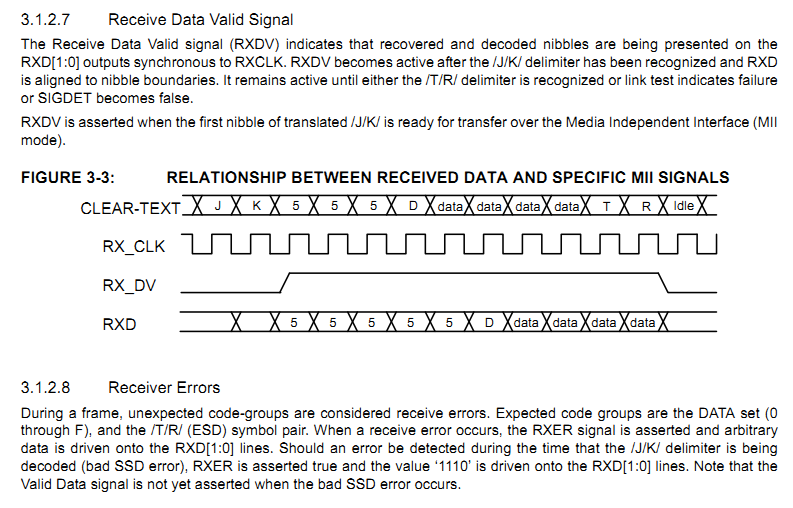
From the RMII spec:
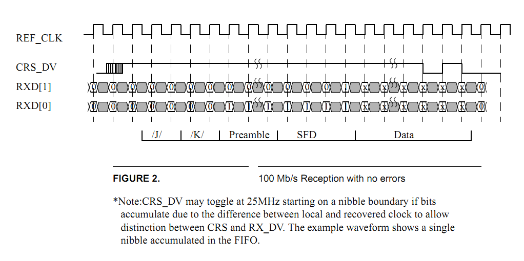
CRS_DV is a combined signal of CRS (carrier sense) and DV (data valid). It becomes active immediately and asynchronously to the local clock as soon as carrier is sensed, i.e. a J/K code group is recognized. CRS becomes inactive earlier than DV because of the elastic FIFO buffer. In this case CRS_DV toggles at 25MHz at the end of a frame.
I am working on a driver since last year.
you might have a look at it
The LAN8720 eval boards have arrived (I bought a bundle of two which was cheaper than a single one).
The first step will be to try to talk to it via the SMI pins, read and write registers and poll the link status. The second will be to record RX data and to examin it looking for possible problems with synchronization. I also can check if I have the corrent understanding of how the CRC is calculated.
I know, at the beginning it would be much easier to have two dedicated cogs, one for receiving and one for transmittting. As I said earlier I don't think that going full duplex is much af an advantage for performance but it avoids collisions and the need for handling collisions is probably more trouble than implementing full duplex.
Thank you very much! I will have a look at it. ... and will come up with lots of questions")
wTX0 long 0 'split into odd & .. wTX1 long 0 '.. even bits (16 bit)flexprop
i connected them for testing
you might be right, so this comment must be fixed in a future version
yes. i enable pullups and hope that the PHY goes into AUTO mode, which does work
receiving should work out of the box
sending is without crc at this time, your pc will drop the packets without notice
it is yet to be finished, i hope i will have time this weekend
OK, first goal achieved. I can read and write from/to the management registers via SMI.")
That was the easier part...
Hmmm.... The status register always reads $7809 which is the default value at startup and should be correct. But it doesn't change if I connect a cable to my switch. I thought auto-negotiate complete and link status should become 1. The data sheet says that auto-negotiation is re-started if the link status changes.
WAIT... WTF! The oscillator on the eval board is 50MHz instead of 25MHz.
  "Ey Beavis, this sucks, you gotta change it!"
The streamer (technically the FIFO) steals hubRAM cycles only as needed on a per clock cycle basis. Cog can still run as normal in parallel, including block copies to and from hubRAM. Combined hubRAM bandwidth of the pair is 32-bits per clock cycle. There is no lose of available bandwidth when shared.
So, at least outgoing packets can be packaged concurrently to transmission.
@evanh Thanks for pointing this out. So WRLONG and RDLONG is still possible while the FIFO (and streamer) is active? This is good news. The silicon docs do not tell whether the two interfere each other but it was my own in terpretation that both use the same resources and therefor can't be used at the same time.
I changed the 50MHz oscillator for a plain 25MHz crystal and it immediately works.") I don't know how this was supposed to be, originally. I know I could have bought a cheap clone board but the 50MHz oscillator is even in the original Waveshare schematic. This would never work. You could use the 50MHz oscillator as external reference clock in the case that the REF_CLK pin is instead used as nINT output. There's actually a jumper (optional 33 ohm resistor) for this signal path. But the LAN8720A will never work without 25MHz at CLKIN/XTAL1. XTAKL2 is not even connected to anything.
I don't know how this was supposed to be, originally. I know I could have bought a cheap clone board but the 50MHz oscillator is even in the original Waveshare schematic. This would never work. You could use the 50MHz oscillator as external reference clock in the case that the REF_CLK pin is instead used as nINT output. There's actually a jumper (optional 33 ohm resistor) for this signal path. But the LAN8720A will never work without 25MHz at CLKIN/XTAL1. XTAKL2 is not even connected to anything. 
The status register now read $782D which means auto-negotiate process completed and link is up.")
Hmm, looking at that datasheet, figure 1, I'm not seeing any external Ethernet port in the diagram of the signals. I'm not even sure which signals are for us.
EDIT: Ah, okay, just downloaded the LAN8720A datasheet as well ... so it's the middle set of signals then.
EDIT2: Well, it's really good news that the Prop2 can supply the reference clock. This makes the bit timings much easier to manage. If the reference clock was derived from the incoming Ethernet clocking then you'd be in trouble.
look at post#1
The LAN8720 only has a REF_CLK output, no input. The P2 could supply the 25MHz crystal clock but that wouldn't save anything. You'd still need the 50MHz reference because you don't know the phase relationship and the TX/TX data is synchronous to the 50MHz clock. So it's better to connect the crystal to the LAN8720A and use the 50MHz clock to feed the XIN input of the P2. So both run synchronously, say, the P2 at a multiple of 50MHz like 200 or 250MHz.
The receiver has a PLL to retrieve the original frequency of the transmitter (remote clock) but that signal is not brought out. Instead, an "elastic" FIFO is used with the remote frequency clocking the input and the local 50MHz clocking the output. CRS_DV is not signaled before the FIFO is half full. This is relatively clever and ensures that the RMII interface is always synchronous to the local clock.
Hmmm, okay, the RMII doc diagram shows the reference clock as external.
I'm thinking the Microchip ENC28J60 might be the wiser direction. An ordinary SPI interface then.
Well, the attribute "wiser" depends on the requirements. Yes, if 10Mbit/s half duplex with no automatic cross over (pair swap) detection is enough for you then the ENC28J60 is a good solution. I've used it for the P1 with great success (>5k units build) for almost 10 years, now. But I think the P2 deserves something newer with a little bit more power. And my personal challange is to write a driver for a 100M ethernet device that consists of less "lines of code" than the ENC28J60 errata sheet.")
@ManAtWork I'm looking forward to your (and other's) RMII PHY efforts reaping some good rewards for the P2
I was thinking about trying this myself at some point but I've got enough on right now. Hopefully this can work out nicely for the P2 and open up even more capabilities.
Lol. That bad eh.
Ok, the next step is trying to capture packets on the receiver side. What makes me wonder is that CRS_DV is high almost all the time after the link is up and auto-negotiation is complete. There are only very narrow low-pulses of two or four clock periods. The LAN8720 is connected to a Netgear switch which is connected to a PC but without any data traffic. The LED at the switch flashes from time to time I think because of windows scanning for new devices, ARP activity and so on.
I drive TX_EN low and have all other RMII pins floating. I don't send anything so the switch doesn't even know my MAC address. All I should get are broadcast packets and there shouldn't be many of them.
Is CRS also active during idle phases and goes low only at the start and the end of data packets?
I'm just reading the LAN8720 datasheet again. On pages 72 and 73 it mentions how to config the REFCLKO pin (pin 14). Namely, when LED2 (pin 2) is pulled low on power up it will enabled the Clock Out on REFCLKO. Guess what, the schematic for the Waveshare board - https://www.waveshare.com/w/upload/0/08/LAN8720-ETH-Board-Schematic.pdf - doesn't pull LED2 low.
That means pin 14 isn't the REFCLKO clock out pin. It is nINT instead. But, irrespective of how that board defaults, most importantly the LAN8720 chip supports an incoming external clock source.
PS: And on page 34 is this little gem: "Note:The REF_CLK Out Mode is not part of the RMII Specification."
3.7.4.1 REF_CLK In Mode
In REF_CLK In Mode, the 50MHz REF_CLK is driven on the XTAL1/CLKIN pin. A 50MHz source for REF_CLK must
be available external to the device when using this mode. The clock is driven to both the MAC and PHY as shown in
Figure 3-7.
I see you were changing a crystal further up. Was that on the LAN board? If so, throw that away too. Use a smartpin for clock gen.