@Cluso99 said:
One last comment, if you combine pins, please leave the option to keep them separate. I use the LCDs with a single row of pins and they plug straight into my RetroBlade2. I haven’t been in need of saving pins with P2 yet.
Good point. That will require some extra instructions to re-initialize the pins before every action because I don't know if it was overwritten by some different operation acting on the same pin, before. But hey, it's just a couple of PASM instructions and should have no performance impact. And it's always a good idea not to break existing setups.
And yes, it's difficult to run out of pins with the P2. But I try to keep things as modular as possible. Connecting the display to a single 12-pin header is kind of "sexy".
@Cluso99 said:
I am also aware (I have a test v3.03) where I realised I set CS but never turn it off.
Who cares if it works... However, this is also kind of "good luck". The data sheet specifies a DC valid to CE low setup time requirement for each byte transfer which can't be met if there is no CE falling edge, of course. If I share pins for SPI of touch and LCD controlers I'll have to turn off CS, anyway, though.
Here are some circle drawing routines I was playing with that use the cordic functions...
...
Nice, thnaks. Unfortunatelly, the call to DrawPixel() is relatively expensive in Spin. So all optimizations of how to calculate the coordinates don't make much difference. That would change if we would move the calculations to the PASM cog. Then pipelined CORDIC commands could be executed while communicating with the display. But that would be a lot of work which would only be justified if you need high performance graphics like for games. And that's definitely not the target for such LCDs although I think the first gameboys had much simpler controllers...
@ManAtWork said:
But that would be a lot of work which would only be justified if you need high performance graphics like for games. And that's definitely not the target for such LCDs although I think the first gameboys had much simpler controllers...
A gameboy (DMG,GBC,GBA, all of them) doesn't have an LCD controller at all, they just have row/column drivers and refresh the display with tile/sprite graphics rendered in real time by the ASIC (well, the original DMG actually makes use of the ability to stop the pixel clock at will to simplify sprite rendering...). Basically the same concept as TV game systems of the time, but at lower resolution.
IIRC some/most/all(?) of the "smart" LCD controllers around these days can actually be put into a "dumb LCD driver" mode, but the pins needed for that are often not brought out.
For performance you would probably use the LCDs with a parallel (8 or 16 bit) bus. Usually the same LCD driver chip but using the parallel mode that is only present on the parallel versions.
That's what I mean. Even when they bring out the pins for the parallel interface, they often omit not only the extra pins neccessary for "dumb" mode BUT ALSO the Vblank signalling pin that would allow tear-free updating of the display buffer in "smart" mode. At least that's what I got from the couple datasheets I read a while ago.
@ManAtWork said:
I've just found this here on GITHUB. Is this the same driver or are there any changes? Which one is the newest version? GIT says V1.0, the one in the first post of this thread has V3.01. All the history/modification info from the source of Greg has been removed.
Ok, I could simply do a pull/fork and compare... But I'm sure others also want to know.
My order from buydisplay has just arrived and I'd like to do some testing...
I had peeled this off and modified it to work with the ili9341 from @Cluso99 's Driver. At the time his driver didn't work with the ili9341. I passed it on to Ken to do some testing and @Cluso99 merged my changes back into his driver. Stick with his driver to get the latest fixes and updates.
@ManAtWork
Can you add in the change log which LCD you were using please (size, resolution and driver chip if known)?
Also, I am interested to see how accurate the touch works for you. I found it was not so accurate on my LCDs.
I have a 1.3" 240x240 ST7789 and 3.5in 480x320 ILI9488 LCD with XPT2046 that did not work properly. I will be interested to retry them with your updates when I get time as it would be nice to see if this fixes the problems. I didn't spend much time on them so it may just be finger trouble or something simple, but could just as easily be timing related too.
@Cluso99 said:
For performance you would probably use the LCDs with a parallel (8 or 16 bit) bus. Usually the same LCD driver chip but using the parallel mode that is only present on the parallel versions.
That's what I mean. Even when they bring out the pins for the parallel interface, they often omit not only the extra pins neccessary for "dumb" mode BUT ALSO the Vblank signalling pin that would allow tear-free updating of the display buffer in "smart" mode. At least that's what I got from the couple datasheets I read a while ago.
My version has a 40-pin header and the Vblank and 8/16 bit parallel signals are all present. Vblank sync is vcalled TE (tearing effect). But as I said I plan to use the display only for relatively slow and simple GUI applications like machine controllers and test equipment. I only need some context sensitive menu/buttons like seen on DSO scopes and some space to display the machine state or error messages. bar graphs or simple waveform graphs would also be nice but no realtime update required.
@Cluso99 said:
@ManAtWork
Can you add in the change log which LCD you were using please (size, resolution and driver chip if known)?
Also, I am interested to see how accurate the touch works for you. I found it was not so accurate on my LCDs.
I have a 1.3" 240x240 ST7789 and 3.5in 480x320 ILI9488 LCD with XPT2046 that did not work properly. I will be interested to retry them with your updates when I get time as it would be nice to see if this fixes the problems. I didn't spend much time on them so it may just be finger trouble or something simple, but could just as easily be timing related too.
My display is an ER-TFTM032-3-3662-4SPI-5V-3807-2559 model. It is 3.2" (diagonal) and has 240x320 pixels resolution. It has a ILI9341 chip and a resistive touch panel with XPT2046 controller. I've just tested the touch feature and it works very nicely. It is precise to +/- 1mm (~5 pixels) when using a pen tip. Of course with "sausage fingers" it's difficult to hit a small spot exactly.
I've cleaned up the calibration procedure a bit. Calibration data is now stored in 4 global longs (offset, scale x/y) so they can be copied to/from flash/eeprom.
I thought I could replace software debouncing of TIRQ with hardware smart pin filters but this doesn't work yet. I have to find out why, later.
Some more optimization: if the repeat while mailbox <> 0 is moved from the end of each spin function issuing a mailbox command to the beginning the drawing action and the calculation of the next point can be executed simultanously by the spin and asm cogs. The new touchscreen poll command is the only one that really has to wait for a result. All drawing actions to the display can be executed as "fire and forget". Only before placing a new command into the mailbox we have to check if it's already empty.
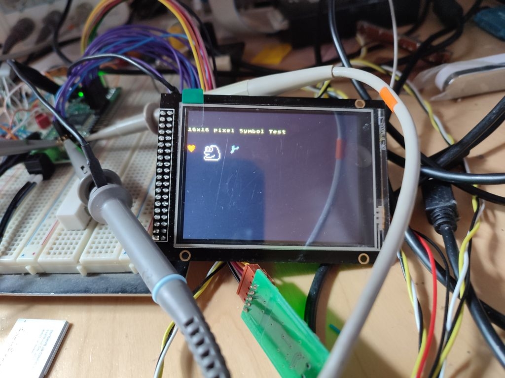
Argh! I ran out of cog RAM and had to move the font to hub RAM. It's actually more efficient because address calculations are much easier, now. No more odd/even word checking and self-modifying code required. And bigger fonts and 16x16 symbols are possible in the future.
Here is an intermediate version if anybody likes to test if I broke something....
I have moved the high level functions (DrawLine() etc.) to the driver object because in Spin it is difficult to include two objects of which the first also includes the second because then you have two instances of the sub-object. And I have deleted some duplicate definitions (colors and rotation constants).
Today, I have successfully modified the driver to allow combining the SPI pins of LCD and touch panel controller. So only 8 port pins are required to run both.
I'll add some support for pushbuttons (automatic touch point window limit checking).
OK, touch/pushbuttons are working. Here is the new driver version.
It would be nice if somebody could check if it still works for other LCD types and separate SPI signals and I haven't broken something accidentally. If everything is fine I'll add it to the OBEX GIT.
@ManAtWork said:
OK, touch/pushbuttons are working. Here is the new driver version.
It would be nice if somebody could check if it still works for other LCD types and separate SPI signals and I haven't broken something accidentally. If everything is fine I'll add it to the OBEX GIT.
On P2Edge & Edge Module Breadboard, I split out the touch pins to separate SPI signals and got it to work. Strange though; without any terminal code (still comments out) I get garbage characters back on the Terminal during touch sequences:
' ER-TFTM032 3.2in 320x240 ILI9341 pinout for use with KISS board. Adjust to suit your P2 board.
  PIN_3V3               = -1                ' 3v3 ~59mA or 5V ~113mA power supplied by power supply
  PIN_GND               = -1                ' GND pwr supplied by power supply
  PIN_CE                = 48    {O}         ' Serial clock enable pin
  PIN_RST               = 49    {O}         ' Reset pin (can be reset by software)
  PIN_DC                = 50    {O}         ' Data / Command selection pin
  PIN_SDA               = 51    {O}         ' Serial Data MOSI pin
  PIN_CLK               = 52    {O}         ' Serial Clock pin
  PIN_LED               = 53 '49    {O}         ' LED backlight enable pin (hi to enable - ~2.4mA)
  PIN_SDO               = 54    {I}         ' Serial Data MISO pin (not used)

' Rules for pin numbers:
' * SDA and CLK must not be more than +/-3 apart
' * TCLK and TDIN must not be more than +/-3 apart
' * TCLK and TDO must not be more than +/-3 apart
' * RST and LED can be combined (assigned the same number)
' * CLK and TCLK can be combined (not supported, yet)
' * SDA and TDIN can be combined
' * SDO and TDO can be combined

  PIN_TCLK              = 22 '52    {O}         '\ Touch: Serial Clock pin
  PIN_TCS               = 23 '53    {O}         '|        Serial clock enable pin
  PIN_TDIN              = 21 '51   {O}         '|        Serial Data In  MOSI pin
  PIN_TDO               = 24 '54   {I}         '|        Serial Data Out MISO pin
  PIN_TIRQ              = 25 '55   {I}         '/        Serial Interrupt out pin
On P2Edge & Edge Module Breadboard, I split out the touch pins to separate SPI signals and got it to work. Strange though; without any terminal code (still comments out) I get garbage characters back on the Terminal during touch sequences:
...
The demo runs well!
Ah, good to know, thanks for testing. The garbage on the terminal probably comes from crosstalk to the unused pins. Although your SPI signals are far away from the serial pins they might be quite sensitive if there's no pullup. You can try if pinl (62) helps.
Ah, good to know, thanks for testing. The garbage on the terminal probably comes from crosstalk to the unused pins. Although your SPI signals are far away from the serial pins they might be quite sensitive if there's no pullup. You can try if pinl (62) helps.
FYI: Setting pin 62 to low (in either the demo code or the driver), didn't seem to make a difference...
Please try pinh(62) in the main object (demo). Because all output states from all cogs are ORed together pinh takes priority and pinl does not. If the garbage stops with pinh then it should indicate that the driver is accidentally driving pin 62.
Interestingly, I haven't seen any garbage characters on my terminal. Are the characters totally random or can you recognize a repeating pattern?
@ManAtWork said:
Please try pinh(62) in the main object (demo). Because all output states from all cogs are ORed together pinh takes priority and pinl does not. If the garbage stops with pinh then it should indicate that the driver is accidentally driving pin 62.
Interestingly, I haven't seen any garbage characters on my terminal. Are the characters totally random or can you recognize a repeating pattern?
With pinh(62) in the main object, there's no change...
Each touch on the screen displays a semi-random glob of text (below, I put returns in to show the pattern)... Each glob starts with ??l8??@?"?
Ah! Its debug info (didn't realize flexprop had it turned on)... I see now the debug command. Anyway, works well with the KISS2 board!
Ah, yes, of course. I'm currently using Propeller Tool. There, you can enable or disable debug output. So I thought it wouldn't hurt to keep the debug statements in the source. I don't know how FlexProp currently handles this. Probably we have to comment it out, although the original intention of debug was to avoid having to comment it out. Also strange that the baud rate was not set correctly. If you don't set it explicitely it should default to something that's compatiple with the baud rate used by loadp2 so that the characters are readable.
@ManAtWork said:
Ah, yes, of course. I'm currently using Propeller Tool. There, you can enable or disable debug output. So I thought it wouldn't hurt to keep the debug statements in the source. I don't know how FlexProp currently handles this. Probably we have to comment it out, although the original intention of debug was to avoid having to comment it out. Also strange that the baud rate was not set correctly. If you don't set it explicitely it should default to something that's compatiple with the baud rate used by loadp2 so that the characters are readable.
flexprop does have an enable/disable debug menu item, so it aligns with PropTool...
The debug data showed up as readable only when I used the KISS 2 board (does the 25MHz clock have anything to do with that?)
I've been using this driver (fetched from the github official community repository) with a few tweaks with great results.
One feature that I would like it to have is to be able to scale the font to a larger size because in small TFTs it could be difficult to see with the standard 6x8 or 8x8 size. For my project I had to do that using spin, but I think it can be too costly for rapid updating of the information on screen. It would be great if that functionality can be baked in the PASM code.
Another modification I had to do was to provide a way to rotate the coordinates of the touch event when the screen is rotated. With the version I downloaded, you could rotate the contents of the screen, but when you touched the screen the coordinates did not rotate. Again, I did this in spin but it would be great to have it handled by the PASM driver directly.
One last modification I think would make the driver even better is if the pins can be assigned at initialization time instead of having them fixed as constants. It would take more memory, but if you are prototyping different projects you might have different pins already assigned and that would require you to change your connections. Fortunately there are plenty of I/Os available but still I think it would be better to parametrize the pins. In my case I had to deviate from the standard pins because I'm using the P2 Edget with 32MB, and that version has fewer pins available.
These are my observations/requests. Unfortunately I don't know how to do this in PASM, otherwise I would have done it and shared it here in the forum.
In case anyone is interested these are the methods I added to scale the 8x8 font:
PUB drawScaledChar8x8(char,size) | r, c, rs, cs, xs, ys
''THIS METHOD SHOULD TO BE CONVERTED INTO PASM TO SPEED IT UP
  setWindow(curx, cury, curx+(8*size-1), cury+(8*size-1))
  xs := curx
  ys := cury

  repeat r from 0 to 7
    repeat rs from 0 to size-1
      repeat c from 0 to 7
        repeat cs from 0 to size-1
          if get_char_bit(char, r, c) == 1
            drawPixel(xs+ cs +(c*size), ys+ rs +(r*size), mailbox3.WORD[1])

  'Update cursor
  curx := xs+8*size
  cury := ys
  mailbox2s := curx << 16 | cury  ' update new (xs, ys, xe, ye) - no need to setWindow!


PRI get_char_bit(char,r,c):bit | d1,d2
  d1, d2 := get_8x8char_data(char)
  bit := (r<4)?d1.BYTE[r].[7-c]:d2.BYTE[r-4].[7-c]


PRI get_8x8char_data(char):d1, d2 | addr, v1
  addr := @font8x8+(char - $20)*8
  ORG

    'd1
    RDLONG  d1, addr
    MOVBYTS d1, #%00_01_10_11  'd1 := BYTE[addr][3] | BYTE[addr][2] << 8 | BYTE[addr][1] << 16 | BYTE[addr][0] << 24

    ADD     addr, #4

    'd2
    RDLONG  d2, addr
    MOVBYTS d2, #%00_01_10_11  'd2 := BYTE[addr][7] | BYTE[addr][6] << 8 | BYTE[addr][5] << 16 | BYTE[addr][4] << 24

  END
@jrullan said:
... if the pins can be assigned at initialization time instead of having them fixed as constants. It would take more memory, but if you are prototyping different projects you might have different pins already assigned and that would require you to change your connections. Fortunately there are plenty of I/Os available but still I think it would be better to parametrize the pins.
Allowing the pin numbers to be arbitrarily assigned to any port pin would be a bit difficult. The synchronous serial smart pin modes require the clock pin to be in the +/-3 range relative to the data pin. The Start() method already calculates the mode bits


Comments
Good point. That will require some extra instructions to re-initialize the pins before every action because I don't know if it was overwritten by some different operation acting on the same pin, before. But hey, it's just a couple of PASM instructions and should have no performance impact. And it's always a good idea not to break existing setups.
And yes, it's difficult to run out of pins with the P2. But I try to keep things as modular as possible. Connecting the display to a single 12-pin header is kind of "sexy".
Who cares if it works... However, this is also kind of "good luck". The data sheet specifies a DC valid to CE low setup time requirement for each byte transfer which can't be met if there is no CE falling edge, of course. If I share pins for SPI of touch and LCD controlers I'll have to turn off CS, anyway, though.
Nice, thnaks. Unfortunatelly, the call to DrawPixel() is relatively expensive in Spin. So all optimizations of how to calculate the coordinates don't make much difference. That would change if we would move the calculations to the PASM cog. Then pipelined CORDIC commands could be executed while communicating with the display. But that would be a lot of work which would only be justified if you need high performance graphics like for games. And that's definitely not the target for such LCDs although I think the first gameboys had much simpler controllers...
A gameboy (DMG,GBC,GBA, all of them) doesn't have an LCD controller at all, they just have row/column drivers and refresh the display with tile/sprite graphics rendered in real time by the ASIC (well, the original DMG actually makes use of the ability to stop the pixel clock at will to simplify sprite rendering...). Basically the same concept as TV game systems of the time, but at lower resolution.
IIRC some/most/all(?) of the "smart" LCD controllers around these days can actually be put into a "dumb LCD driver" mode, but the pins needed for that are often not brought out.
For performance you would probably use the LCDs with a parallel (8 or 16 bit) bus. Usually the same LCD driver chip but using the parallel mode that is only present on the parallel versions.
That's what I mean. Even when they bring out the pins for the parallel interface, they often omit not only the extra pins neccessary for "dumb" mode BUT ALSO the Vblank signalling pin that would allow tear-free updating of the display buffer in "smart" mode. At least that's what I got from the couple datasheets I read a while ago.
I had peeled this off and modified it to work with the ili9341 from @Cluso99 's Driver. At the time his driver didn't work with the ili9341. I passed it on to Ken to do some testing and @Cluso99 merged my changes back into his driver. Stick with his driver to get the latest fixes and updates.
@ManAtWork
Can you add in the change log which LCD you were using please (size, resolution and driver chip if known)?
Also, I am interested to see how accurate the touch works for you. I found it was not so accurate on my LCDs.
I have a 1.3" 240x240 ST7789 and 3.5in 480x320 ILI9488 LCD with XPT2046 that did not work properly. I will be interested to retry them with your updates when I get time as it would be nice to see if this fixes the problems. I didn't spend much time on them so it may just be finger trouble or something simple, but could just as easily be timing related too.
My version has a 40-pin header and the Vblank and 8/16 bit parallel signals are all present. Vblank sync is vcalled TE (tearing effect). But as I said I plan to use the display only for relatively slow and simple GUI applications like machine controllers and test equipment. I only need some context sensitive menu/buttons like seen on DSO scopes and some space to display the machine state or error messages. bar graphs or simple waveform graphs would also be nice but no realtime update required.
My display is an ER-TFTM032-3-3662-4SPI-5V-3807-2559 model. It is 3.2" (diagonal) and has 240x320 pixels resolution. It has a ILI9341 chip and a resistive touch panel with XPT2046 controller. I've just tested the touch feature and it works very nicely. It is precise to +/- 1mm (~5 pixels) when using a pen tip. Of course with "sausage fingers" it's difficult to hit a small spot exactly.
IIRC there are some register settings that can prevent tearing.
There is also scrolling but I couldn't make it work when in landscape mode, only in portrait mode
I've cleaned up the calibration procedure a bit. Calibration data is now stored in 4 global longs (offset, scale x/y) so they can be copied to/from flash/eeprom.
I thought I could replace software debouncing of TIRQ with hardware smart pin filters but this doesn't work yet. I have to find out why, later.
Some more optimization: if the
repeat while mailbox <> 0is moved from the end of each spin function issuing a mailbox command to the beginning the drawing action and the calculation of the next point can be executed simultanously by the spin and asm cogs. The new touchscreen poll command is the only one that really has to wait for a result. All drawing actions to the display can be executed as "fire and forget". Only before placing a new command into the mailbox we have to check if it's already empty.Argh! I ran out of cog RAM and had to move the font to hub RAM. It's actually more efficient because address calculations are much easier, now. No more odd/even word checking and self-modifying code required. And bigger fonts and 16x16 symbols are possible in the future.
Here is an intermediate version if anybody likes to test if I broke something....
I have moved the high level functions (DrawLine() etc.) to the driver object because in Spin it is difficult to include two objects of which the first also includes the second because then you have two instances of the sub-object. And I have deleted some duplicate definitions (colors and rotation constants).
Two-color bitmap icons up to 64x64 pixels are supported, now.
Nice
Today, I have successfully modified the driver to allow combining the SPI pins of LCD and touch panel controller. So only 8 port pins are required to run both.
I'll add some support for pushbuttons (automatic touch point window limit checking).
OK, touch/pushbuttons are working. Here is the new driver version.
It would be nice if somebody could check if it still works for other LCD types and separate SPI signals and I haven't broken something accidentally. If everything is fine I'll add it to the OBEX GIT.
On P2Edge & Edge Module Breadboard, I split out the touch pins to separate SPI signals and got it to work. Strange though; without any terminal code (still comments out) I get garbage characters back on the Terminal during touch sequences:
' ER-TFTM032 3.2in 320x240 ILI9341 pinout for use with KISS board. Adjust to suit your P2 board. PIN_3V3 = -1 ' 3v3 ~59mA or 5V ~113mA power supplied by power supply PIN_GND = -1 ' GND pwr supplied by power supply PIN_CE = 48 {O} ' Serial clock enable pin PIN_RST = 49 {O} ' Reset pin (can be reset by software) PIN_DC = 50 {O} ' Data / Command selection pin PIN_SDA = 51 {O} ' Serial Data MOSI pin PIN_CLK = 52 {O} ' Serial Clock pin PIN_LED = 53 '49 {O} ' LED backlight enable pin (hi to enable - ~2.4mA) PIN_SDO = 54 {I} ' Serial Data MISO pin (not used) ' Rules for pin numbers: ' * SDA and CLK must not be more than +/-3 apart ' * TCLK and TDIN must not be more than +/-3 apart ' * TCLK and TDO must not be more than +/-3 apart ' * RST and LED can be combined (assigned the same number) ' * CLK and TCLK can be combined (not supported, yet) ' * SDA and TDIN can be combined ' * SDO and TDO can be combined PIN_TCLK = 22 '52 {O} '\ Touch: Serial Clock pin PIN_TCS = 23 '53 {O} '| Serial clock enable pin PIN_TDIN = 21 '51 {O} '| Serial Data In MOSI pin PIN_TDO = 24 '54 {I} '| Serial Data Out MISO pin PIN_TIRQ = 25 '55 {I} '/ Serial Interrupt out pinTerminal output:
$ ./loadp2 -p /dev/cu.usbserial-A601RZ6G -b230400 @0=./flexprop/board/P2ES_flashloader.bin,@8000+./Downloads/LCD_Graphics_Driver_V3-2/LCD_Graphics_Demo.binary -t -k; osascript -e 'tell application "Wish" to activate'; exit 0 ( Entering terminal mode. Press Ctrl-] or Ctrl-Z to exit. ) P2-ES Flash Programmer Erasing flash... Programming... Done ??l8??@?"?{?&??Y"?s????l8??@?"?"t#??Y"?:ט????l8??@?"? LY"?????l8??@?"?s?#??Y"??g???l8??@?"?cLY"?????l8??@?"?c?&??Y"?????l8??@?"??&??Y"?Z????l8??@?"??Y"??????l8??@?"?"?\Y?@?"?"?????l8??@?"????Y"?The demo runs well!
Lest i forget an image:
Ah, good to know, thanks for testing. The garbage on the terminal probably comes from crosstalk to the unused pins. Although your SPI signals are far away from the serial pins they might be quite sensitive if there's no pullup. You can try if
pinl (62)helps.FYI: Setting pin 62 to low (in either the demo code or the driver), didn't seem to make a difference...
Please try
pinh(62)in the main object (demo). Because all output states from all cogs are ORed together pinh takes priority and pinl does not. If the garbage stops with pinh then it should indicate that the driver is accidentally driving pin 62.Interestingly, I haven't seen any garbage characters on my terminal. Are the characters totally random or can you recognize a repeating pattern?
With pinh(62) in the main object, there's no change...
Each touch on the screen displays a semi-random glob of text (below, I put returns in to show the pattern)... Each glob starts with
??l8??@?"?Ah! Its debug info (didn't realize flexprop had it turned on)... I see now the debug command. Anyway, works well with the KISS2 board!
Puts out:
Ah, yes, of course. I'm currently using Propeller Tool. There, you can enable or disable debug output. So I thought it wouldn't hurt to keep the debug statements in the source. I don't know how FlexProp currently handles this. Probably we have to comment it out, although the original intention of debug was to avoid having to comment it out. Also strange that the baud rate was not set correctly. If you don't set it explicitely it should default to something that's compatiple with the baud rate used by loadp2 so that the characters are readable.
flexprop does have an enable/disable debug menu item, so it aligns with PropTool...
The debug data showed up as readable only when I used the KISS 2 board (does the 25MHz clock have anything to do with that?)
Wait.... I think you have to remove the
in the CON section of the Demo if you don't use the KISS board. _xtlfreq then defaults to 20MHz which is perfect for any other board.

Yes, I got that! Thx
Hello,
I've been using this driver (fetched from the github official community repository) with a few tweaks with great results.
One feature that I would like it to have is to be able to scale the font to a larger size because in small TFTs it could be difficult to see with the standard 6x8 or 8x8 size. For my project I had to do that using spin, but I think it can be too costly for rapid updating of the information on screen. It would be great if that functionality can be baked in the PASM code.
Another modification I had to do was to provide a way to rotate the coordinates of the touch event when the screen is rotated. With the version I downloaded, you could rotate the contents of the screen, but when you touched the screen the coordinates did not rotate. Again, I did this in spin but it would be great to have it handled by the PASM driver directly.
One last modification I think would make the driver even better is if the pins can be assigned at initialization time instead of having them fixed as constants. It would take more memory, but if you are prototyping different projects you might have different pins already assigned and that would require you to change your connections. Fortunately there are plenty of I/Os available but still I think it would be better to parametrize the pins. In my case I had to deviate from the standard pins because I'm using the P2 Edget with 32MB, and that version has fewer pins available.
These are my observations/requests. Unfortunately I don't know how to do this in PASM, otherwise I would have done it and shared it here in the forum.
In case anyone is interested these are the methods I added to scale the 8x8 font:
PUB drawScaledChar8x8(char,size) | r, c, rs, cs, xs, ys ''THIS METHOD SHOULD TO BE CONVERTED INTO PASM TO SPEED IT UP setWindow(curx, cury, curx+(8*size-1), cury+(8*size-1)) xs := curx ys := cury repeat r from 0 to 7 repeat rs from 0 to size-1 repeat c from 0 to 7 repeat cs from 0 to size-1 if get_char_bit(char, r, c) == 1 drawPixel(xs+ cs +(c*size), ys+ rs +(r*size), mailbox3.WORD[1]) 'Update cursor curx := xs+8*size cury := ys mailbox2s := curx << 16 | cury ' update new (xs, ys, xe, ye) - no need to setWindow! PRI get_char_bit(char,r,c):bit | d1,d2 d1, d2 := get_8x8char_data(char) bit := (r<4)?d1.BYTE[r].[7-c]:d2.BYTE[r-4].[7-c] PRI get_8x8char_data(char):d1, d2 | addr, v1 addr := @font8x8+(char - $20)*8 ORG 'd1 RDLONG d1, addr MOVBYTS d1, #%00_01_10_11 'd1 := BYTE[addr][3] | BYTE[addr][2] << 8 | BYTE[addr][1] << 16 | BYTE[addr][0] << 24 ADD addr, #4 'd2 RDLONG d2, addr MOVBYTS d2, #%00_01_10_11 'd2 := BYTE[addr][7] | BYTE[addr][6] << 8 | BYTE[addr][5] << 16 | BYTE[addr][4] << 24 ENDAllowing the pin numbers to be arbitrarily assigned to any port pin would be a bit difficult. The synchronous serial smart pin modes require the clock pin to be in the +/-3 range relative to the data pin. The Start() method already calculates the mode bits
But there have to be additional checks.
I also planned to provide larger fonts. But instead of scaling the 8x8 font up I'd rather use the 32x32 font from the P1 ROM and scale it down.